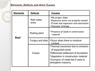
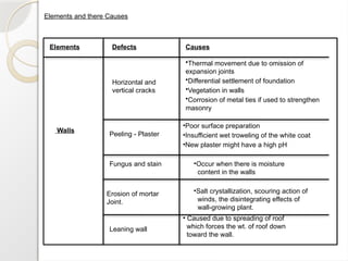
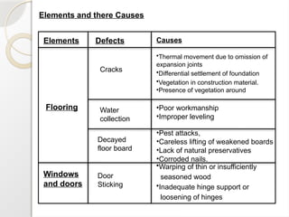
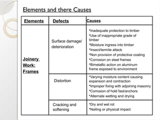
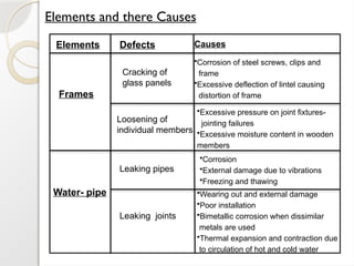
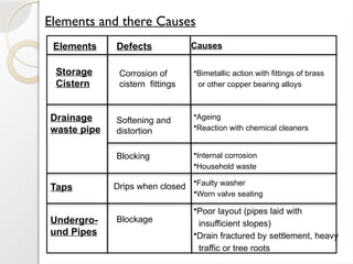
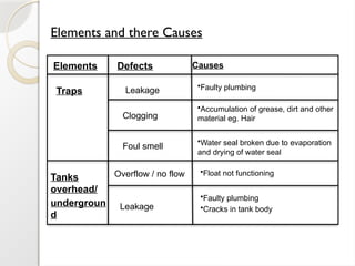
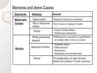
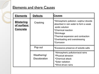
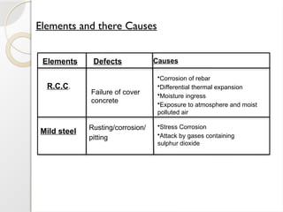
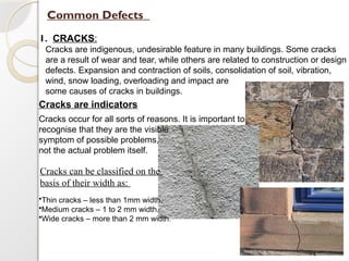
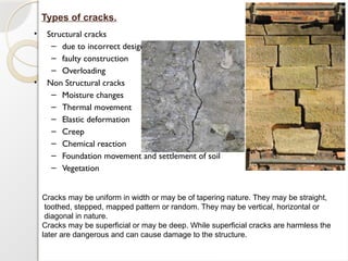
Name Komal khan
Roll no 15
Semester 3rd
CONTENTS
•Defects in buildings.
•Causes of defects in buildings.
•Elements ,Defects and there Causes
•Common Defects and there respective remedy
1. Cracks.
Causes of Cracks.
Preventive Measures to avoid Cracks.
•Non destructive tests:-
1. Rebound test.
2. Penetration test.
•Rehabilitation methods:-
Grouting.
Guniting.
Jacketing.
•General chemicals used in construction and repairing work:-
1.Admixtures:
•Retarder.
•Accelerator.
•Plasticizer.
•Super plasticizer.
•Air entraining agent.
•Water proofer.
•Pigments.
Defects in buildings
A building defect is that which makes a project dangerous, unsafe or causes
real
damage.
Building defects affect society at large due to possible danger posed; they also
result
in direct
and indirect cost in repairs, abnormally high maintenance, disputes and
possible loss
of building
use.
Defects are generally caused by inadequacies in design, poor
workmanship, building usage
not in
accordance with design and lack of or incorrect maintenance. Within the
realm of building or
remodeling your home, construction defects are much like a cancer that
eats away at your
very core,
your physical integrity, your strength and ultimately your ability to exist.
As building conservation often involves various remedial works and building repairs, a
thorough identification and recording of building defects are integral in determining the
appropriate conservation methods and techniques to be employed.
Causes of defects in buildings
• Water or dampness
• Physical movement due to forces
• Effect of environmental factors
Defects are generally caused by inadequacies in design, poor workmanship,
building usage not in accordance with design and lack of or incorrect maintenance.
Within the realm of building or remodeling your home, construction defects are
much like a cancer that eats away at your very core, your physical integrity, your
strength and ultimately your ability to exist.
Elements ,Defects and there Causes
Elements Defects
Rain water
entry
Fungus and stain
Cracks
•Occur when there is moisture
content
Peeling plant
• Presence of seeds in construction
material
Causes
Roof
•No proper slope.
•Expansion joints not properly treated
•Cracks due expansion and contraction
•Improper drainage
•Thermal movement due to omission
of expansion joints
•Differential settlement of foundation
•Vegetation in construction material
•Corrosion of metal ties if used to
strengthen masonry
Elements and there Causes
Defects
Horizontal and
vertical cracks
Peeling - Plaster
Fungus and stain
Erosion of mortar
Joint.
•Thermal movement due to omission of
expansion joints
•Differential settlement of foundation
•Vegetation in walls
•Corrosion of metal ties if used to strengthen
masonry
•Poor surface preparation
•Insufficient wet troweling of the white coat
•New plaster might have a high pH
•Occur when there is moisture
content in the walls
•Salt crystallization, scouring action of
winds, the disintegrating effects of
wall-growing plant.
Leaning wall
• Caused due to spreading of roof
which forces the wt. of roof down
toward the wall.
Causes
Elements
Walls
Defects
Horizontal and
vertical cracks
Peeling - Plaster
Fungus and stain
Erosion of mortar
Joint.
•Thermal movement due to omission of
expansion joints
•Differential settlement of foundation
•Vegetation in walls
•Corrosion of metal ties if used to strengthen
masonry
•Poor surface preparation
•Insufficient wet troweling of the white coat
•New plaster might have a high pH
•Occur when there is moisture
content in the walls
•Salt crystallization, scouring action of
winds, the disintegrating effects of
wall-growing plant.
Leaning wall
• Caused due to spreading of roof
which forces the wt. of roof down
toward the wall.
Causes
Elements and there Causes
Elements
Flooring
Defects
Cracks
•Thermal movement due to omission of
expansion joints
•Differential settlement of foundation
•Vegetation in construction material.
•Presence of vegetation around
Causes
Water
collection
•Poor workmanship
•Improper leveling
Decayed
floor board
•Pest attacks,
•Careless lifting of weakened boards
•Lack of natural preservatives
•Corroded nails.
Windows
and doors
Door
Sticking
•Warping of thin or insufficiently
seasoned wood
•Inadequate hinge support or
loosening of hinges
Elements and there Causes
Elements
Foundation
Defects Causes
Uneven
settlement
•Including shrinking clay soil
•Water level
•Increased loads
•Deteriorating of building materials
Cracks
•Presence of vegetation around
•Deteriorating of building materials
•Corrosion of metal ties if used to
strengthen masonry
Elements and there Causes
Elements Defects Causes
Joinery
Work:
Frames
Surface damage/
deterioration
•Inadequate protection to timber
•Use of inappropriate grade of
timber
•Moisture ingress into timber
•Insect/termite attack
•Non provision of protective coating
•Corrosion on steel frames
•Bimetallic action on aluminum
frame exposed to environment
Distortion
•Varying moisture content causing
expansion and contraction
•Improper fixing with adjoining masonry
•Corrosion of hold fast/anchors
•Alternate wetting and drying
Cracking and
softening
•Dry and wet rot
•Nailing or physical impact
Elements and there Causes
Elements Defects Causes
Cracking of
glass panels
•Corrosion of steel screws, clips and
frame
•Excessive deflection of lintel causing
distortion of frame
Loosening of
individual members
•Excessive pressure on joint fixtures-
jointing failures
•Excessive moisture content in wooden
members
Water- pipe
Leaking pipes
•Corrosion
•External damage due to vibrations
•Freezing and thawing
Leaking joints
•Wearing out and external damage
•Poor installation
•Bimetallic corrosion when dissimilar
metals are used
•Thermal expansion and contraction due
to circulation of hot and cold water
Frames
Elements and there Causes
Elements Defects Causes
Storage
Cistern
Corrosion of
cistern fittings
•Bimetallic action with fittings of brass
or other copper bearing alloys
Drainage
waste pipe
•Ageing
•Reaction with chemical cleaners
Softening and
distortion
Blocking •Internal corrosion
•Household waste
Taps Drips when closed
•Faulty washer
•Worn valve seating
Undergro-
und Pipes
Blockage
•Poor layout (pipes laid with
insufficient slopes)
•Drain fractured by settlement, heavy
traffic or tree roots
Elements and there Causes
Elements Defects Causes
Traps Leakage
•Faulty plumbing
Clogging
Foul smell
•Accumulation of grease, dirt and other
material eg. Hair
•Water seal broken due to evaporation
and drying of water seal
Tanks
overhead/
undergroun
d
Overflow / no flow
Leakage
•Float not functioning
•Faulty plumbing
•Cracks in tank body
Elements and there Causes
Elements Defects Causes
Materials:
Timber
Bricks
Deformation •Seasonal moisture movement
Rot in structural
timber
•Dry rot due to ingress of water
Decay
•Insect/ termite attack
•Continuous dampness
White powdering
deposit
Staining of bricks
Decay
•Efflorescence caused by crystallization
of soluble salts in brick or mortar
•Sulphate attack
•Efflorescence
•Dampness
•Absorption of chemical salts
•Crystallization of salts formed
below the surface in brick crevices
Elements and there Causes
Elements Defects Causes
Weathering/
Discoloration
Blistering
of surface:
Concrete
Cracking
•Atmospheric pollution- sulphur dioxide
absorbed in rain water to form a weak
acidic solution
•Chemical reaction
•Shrinkage
•Thermal expansion and contraction
•Overloading and overstressing
•Corrosion
Pop out •Excessive presence of soluble salts
•Atmospheric pollution/acid rains
•Physical abrasion
•Chemical attack
•Solar radiation
•Wind driven rains
Elements and there Causes
Elements Defects Causes
R.C.C.
Failure of cover
concrete
•Corrosion of rebar
•Differential thermal expansion
•Moisture ingress
•Exposure to atmosphere and moist
polluted air
Mild steel Rusting/corrosion/
pitting
•Stress Corrosion
•Attack by gases containing
sulphur dioxide
Common Defects
1. CRACKS:
Cracks are indigenous, undesirable feature in many buildings. Some cracks
are a result of wear and tear, while others are related to construction or design
defects. Expansion and contraction of soils, consolidation of soil, vibration,
wind, snow loading, overloading and impact are
some causes of cracks in buildings.
Cracks are indicators
Cracks occur for all sorts of reasons. It is important to
recognise that they are the visible
symptom of possible problems,
not the actual problem itself.
•Thin cracks – less than 1mm width.
•Medium cracks – 1 to 2 mm width.
•Wide cracks – more than 2 mm width.
Cracks can be classified on the
basis of their width as:
• Structural cracks
– due to incorrect design
– faulty construction
– Overloading
• Non Structural cracks
– Moisture changes
– Thermal movement
– Elastic deformation
– Creep
– Chemical reaction
– Foundation movement and settlement of soil
– Vegetation
Types of cracks.
Cracks may be uniform in width or may be of tapering nature. They may be straight,
toothed, stepped, mapped pattern or random. They may be vertical, horizontal or
diagonal in nature.
Cracks may be superficial or may be deep. While superficial cracks are harmless the
later are dangerous and can cause damage to the structure.
Moisture changes:
Most of the Building materials having pores in the form of intra molecular spaces expand on
absorbing moisture and shrink on drying. These movements are generally reversible and cracks
formed due to the movement of moisture may vary in width as per the seasonal changes. Some
of the movements are irreversible in nature and cracks formed due to this remain permanent.
Shrinkage in concrete or mortar depends on a number of factors.
•Cement concrete: Richer the mix greater is the drying shrinkage.
•Water content: More water in mix induces greater shrinkage
•Aggregates: Large aggregates with good grading has less shrinkage for same workability
as less water is used.
•Curing: If proper curing starts as soon as initial set has taken place and continued for 7 to 10 days
shrinkage is comparatively less.
•Excessive fines: More fines in aggregate requires more water for same workability and hence
more shrinkage.
•Temperature: Concrete made in hot weather needs more water for same workability hence it
results in more shrinkage.
Materials having small moisture movement are burnt clay bricks, igneous rocks, limestone,
marble and metals.
Materials having moderate moisture movement are concrete, sandstone, mortars.
Materials having high moisture movement are timber, block boards, plywood, wood cement
products, asbestos sheet.
CAUSES OF CRACKS:
The principal causes of cracks are:
Prevention:
Use minimum quantity of water required for mixing cement concrete or cements mortar according
to water cement ratio. Never allow cement concrete work without mechanical mix and vibrator.
Thermal variations:
Thermal variations:
Building materials more or less expand on heating and contract on cooling. The
magnitude of expansion differs from material to material as per their molecular structure.
The extent of thermal expansion and contraction depends on temperature variation,
dimension of element, coefficient of expansion, color and surface properties and internally
generated heat in case of wet concrete.
. The cracking of a typical structure due to thermal movement is given in fig
• In case of framed buildings due to thermal movement frames are distorted and cracks
may appear as shown in fig
Thermal change is not in our
hands but the preventive
measures are. Hence architect
must understand the preventive
measures as well as the initial
step to prevent the cracks.
Prevention of Thermal Cracks
• To prevent thermal cracks expansion joints, control joints and joints in case
of change of shape and direction of wing in a structure are to be provided.
General guide lines to provide movement joints
Type of Structure Movement of Joints
a RCC roof slab Provide 20 to 25 mm wide, joint at 10 to 20 M apart
b Supports for RCC slabs 4 to 6M
length
Provide slip joint between slab and bearing wall.
c RCC framed structure, other load
and bearing structure
Provide 25 to 40 mm wide expansion Joints at 30 to 45 M interval
d Junction between old and new
structure
Provide vertical slip joints.
e Compound walls Expansion joint 5 to 8mm wide at 5to 8M interval and change of
direction.
f Concrete pavement Provide 20 to 25mm wide joints at 25m to 40m interval with
control joints at 5 to 8m. In cross direction control joints have to
be provided at 3 to 5 m intervals.
g Chajja Provide expansion joint 5 to 8mm wide at 4 to 6 M interval.
h RCC Railing Provide expansion joints 5 to 8mm wide at 6 to 9m interval.
Structural members of a building undergo elastic deformation due to the imposition of
load which cause cracking in the members.
Elastic Deformation
A change in dimensions of an object under load that is fully recovered when the
load is removed. That part of the deformation in a stressed body which
disappears upon removal of the stress.
Creep
Building items such as concrete and brick work when subjected to a sustained load
not only undergo elastic strain but also develop gradual and slow time dependent
deformation known as creep or plastic strain. The creep in brick work may stop after 4
months but the same in concrete continue up to a year or so. The creep in concrete may
be 2 to 3 times of the elastic deformation and hence has to be fully care fully considered.
Creep
“Creep”:Time-dependent increase in deformation
under sustained stress
“Relaxation”: time-dependent decrease in stress
under sustained deformation
Prestress loss, settlements, buckling of columns
Generally, time-dependent strains do no affect
load capacity of a member at collapse. However,
when instability is a factor, then creep can affect
the failure load,e.g. a column under load
(subjected to the time depended influences of
creep and shrinkage) may have its safety reduced
with time.
General measures for avoidance reduction of cracks due to elastic
strain, creep and shrinkage
• Water cement ratio is to be controlled.
• Reasonable pace of construction adopted.
• Brick work over load bearing RCC members should be done after removal of
shutting giving a time gap.
• Brick walls between columns should be deferred as much as possible.
• Plastering of areas having RCC and brick members should be done after sufficient
time gap say one month or suitable groves provided in junction.
• Shutting should be allowed stay for a larger period say 30 days or so for cantilevers
which are bound to defect appreciably.
Movement due to chemical reaction
• Certain chemical reaction in building materials result is appreciable change in
volume of resulting products and internal stresses are set up which may result in
outward thrust and formation of cracks.
• Soluble sulphate reacts with tricalcium aluminates in cement and hydraulic lime
and form products which occupy larger volume and ends in developing cracks. An
example of cracking of a floor due to coming in contact of the sub base made of
brick khoa with heavy sulphate content and water can be seen in fig. below
Prevention
•If sulphate content in soil is more that 0.2 % or in ground water more than 300 ppm use
rich mix of concrete mortar has to be adopted.
•Avoid bricks containing too much soluble sulphates (more than 5 %) and use rich mortar
in such cases.
•Use expansion and control joint at closure intervals
Corrosion of Reinforcement
Corroded reinforcement expands and cracks the concrete cover. To avoid this
phenomenon rich mix of concrete using proper quality of water and adequate cover
should adopted.
Foundation movement and settlement of soil
Building on expansion clays are extremely crack prone. The soil movement in such clay
is more appreciable upto a depth of 1.5 to 2M and this cause swelling and shrinkage and
results in crack in the structure. The cracks due to settlement are usually diagonal in
shape. Crack appearing due to swelling is vertical Fig
Cracking due to vegetation
Large trees growing in the vicinity of buildings cause damage in all type of soil conditions.
If the soil is shrinkable clay, cracking is severe in those conditions
Prevention:
Do not let trees grow too close to the buildings, compound walls etc. Remove any
saplings of trees as soon as possible if they start growing in or near of walls etc.
Foundation/floor settlement:
Shear cracks in building occur where there is large differential settlement of
foundation due to unequal bearing pressure under different parts of the structure or due
to the excessive loading on foundation. Cracks are caused many times due to swelling o
soil due to the moisture absorption. Cracks in the flooring are observed due to the
compaction of the filling material in plinth at a later stage. Foundation and plinth of
building constructed over expansive soils such as black cotton soil are subjected to
upward thrust in rainy season due to moisture absorption causing cracks in
superstructure.
Prevention:
The design of foundation must be based on sound engineering principles and good
practice.
Cracks in the building elements are also caused due to the substandard workmanship
and bad construction practices, the main areas where the cracks are seen are brick
walls, plastered surfaces, slabs and flooring. The positions where these are seen are
the junctions of concrete and brick work, sill and lintel portions of walls, junctions of
walls and flooring material, balcony parapet walls, parapet copings. These cracks may
be caused to excessive rich mortar brick work causing shrinkage.
Poor workmanship:
2. Seepage
The process by which a liquid leaks through a porous substance. Seepage may be from
cut or natural slopes.
Anything which contains the water will face the problem of seepage and seepage
problem will be also be there if water content ratio is high.
General measures to avoid seepage
Seepage controlling measures starts from the construction of the thing which water
has to be kept in.
To control the seepage it is important to use the good quality construction material.
Care should be taken that no cracks can arrive in course of time.
Water proofing compound and techniques should be used.
Non destructive test.
Nondestructive testing asks "Is there something wrong with this material?"
Various performance and proof tests, in contrast, ask "Does this component
work?“
• The idea of future usefulness is relevant to the quality control practice of sampling.
Sampling is nondestructive testing if the tested sample is returned to service.
e.g. If the steel is tested to verify the alloy in some bolts that can then be returned to
service then the test is nondestructive. In contrast, even if spectroscopy used in the
chemical testing of many fluids is inherently nondestructive, the process is destructive
if the test samples are discarded after testing.
•It is a controlled test which is done with the
machine and we get the assured of quality control
and we get a proof of that material.
• NDT provides an excellent balance between quality
control and cost-effectiveness.
NDE Test .
• Non-destructive evaluation (NDE) is a term that is
often used interchangeably with NDT.
• The nondestructive testing is not confined to crack
detection but an NDE method would not only locate
a defect, but it would also be used to measure about that defect such as
its size, shape, and orientation.
The rebound hammer is a surface hardness tester for which an empirical correlation
has been established between strength and rebound number.
Non destructive test.
•Rebound test
•Penetration test
•Pull-Out Tests
•Dynamic Tests
•Radioactive Methods
Advantage
• Ensures the Integrity and Reliability of a Product.
• Prevents Accidents and Saving Lives
• Ensures Customer Satisfaction
•Aiding in Product Design
•Controlling Manufacturing Processes
• Maintaining Uniform Quality Level
List Non destructive test.
Rebound test.
The only known instrument to make use of the rebound principle for concrete testing is
the Schmidt hammer and is suitable for both laboratory and field work.
1.The underlying principle of the rebound hammer test is that the rebound of an
elastic mass depends on the hardness of the surface against which its mass strikes.
2. The hammer is forced against the surface of the concrete by the spring and the
distance of rebound is measured on a scale. The test surface can be horizontal,
vertical or at any angle but the instrument must be calibrated in this position.
3. The surface hardness and therefore the rebound is taken to be related to the
compressive strength of the concrete. The rebound value is read from a graduated
scale and is designated as the rebound number or rebound index. The compressive
strength can be read directly from the graph provided on the body of the hammer.
4. The Schmidt hammer provides an inexpensive, simple and quick method of obtaining
an indication of concrete strength, but accuracy of ±15 to ±20 percent is possible.
5. The results are affected by factors such as smoothness of surface, size and shape of
specimen, moisture condition of the concrete, type of cement and coarse aggregate,
and extent of carbonation of surface.
Procedure to determine strength of hardened concrete by rebound
hammer;
1.Before commencement of a test, the rebound hammer should be tested against
test anvil, to get reliable results, for which the manufacturer of the rebound hammer
indicates the range of readings on the anvil suitable for different types of rebound
hammer.
2. Apply light pressure on the plunger – it will release it from the locked position and
allow it to extend to the ready position for the test.
3.Press the plunger against the surface of the concrete, keeping the instrument
perpendicular to the test surface. Apply a gradual increase in pressure until the
hammer impacts. (Do not touch the button while depressing the plunger. Press the
button after impact, in case it is not convenient to note the rebound reading in that
position.)
4. Take the average of about 15 readings.
Penetration test
• This is a method which can be employed for the detection of open-to-surface
discontinuities in any industrial product which is made from a non-porous
material.Other name for same test is liquid PT.
• A liquid penetrate is applied to the surface of the product for a certain
predetermined time, after which the excess penetrate is removed from the
surface.
defects in building MATERIAL CONSTRUCTION.pptx

defects in building MATERIAL CONSTRUCTION.pptx

  • 1.
    Name Komal khan Rollno 15 Semester 3rd
  • 2.
    CONTENTS •Defects in buildings. •Causesof defects in buildings. •Elements ,Defects and there Causes •Common Defects and there respective remedy 1. Cracks. Causes of Cracks. Preventive Measures to avoid Cracks. •Non destructive tests:- 1. Rebound test. 2. Penetration test. •Rehabilitation methods:- Grouting. Guniting. Jacketing. •General chemicals used in construction and repairing work:- 1.Admixtures: •Retarder. •Accelerator. •Plasticizer. •Super plasticizer. •Air entraining agent. •Water proofer. •Pigments.
  • 3.
    Defects in buildings Abuilding defect is that which makes a project dangerous, unsafe or causes real damage. Building defects affect society at large due to possible danger posed; they also result in direct and indirect cost in repairs, abnormally high maintenance, disputes and possible loss of building use. Defects are generally caused by inadequacies in design, poor workmanship, building usage not in accordance with design and lack of or incorrect maintenance. Within the realm of building or remodeling your home, construction defects are much like a cancer that eats away at your very core, your physical integrity, your strength and ultimately your ability to exist. As building conservation often involves various remedial works and building repairs, a thorough identification and recording of building defects are integral in determining the appropriate conservation methods and techniques to be employed.
  • 4.
    Causes of defectsin buildings • Water or dampness • Physical movement due to forces • Effect of environmental factors Defects are generally caused by inadequacies in design, poor workmanship, building usage not in accordance with design and lack of or incorrect maintenance. Within the realm of building or remodeling your home, construction defects are much like a cancer that eats away at your very core, your physical integrity, your strength and ultimately your ability to exist.
  • 5.
    Elements ,Defects andthere Causes Elements Defects Rain water entry Fungus and stain Cracks •Occur when there is moisture content Peeling plant • Presence of seeds in construction material Causes Roof •No proper slope. •Expansion joints not properly treated •Cracks due expansion and contraction •Improper drainage •Thermal movement due to omission of expansion joints •Differential settlement of foundation •Vegetation in construction material •Corrosion of metal ties if used to strengthen masonry
  • 6.
    Elements and thereCauses Defects Horizontal and vertical cracks Peeling - Plaster Fungus and stain Erosion of mortar Joint. •Thermal movement due to omission of expansion joints •Differential settlement of foundation •Vegetation in walls •Corrosion of metal ties if used to strengthen masonry •Poor surface preparation •Insufficient wet troweling of the white coat •New plaster might have a high pH •Occur when there is moisture content in the walls •Salt crystallization, scouring action of winds, the disintegrating effects of wall-growing plant. Leaning wall • Caused due to spreading of roof which forces the wt. of roof down toward the wall. Causes Elements Walls Defects Horizontal and vertical cracks Peeling - Plaster Fungus and stain Erosion of mortar Joint. •Thermal movement due to omission of expansion joints •Differential settlement of foundation •Vegetation in walls •Corrosion of metal ties if used to strengthen masonry •Poor surface preparation •Insufficient wet troweling of the white coat •New plaster might have a high pH •Occur when there is moisture content in the walls •Salt crystallization, scouring action of winds, the disintegrating effects of wall-growing plant. Leaning wall • Caused due to spreading of roof which forces the wt. of roof down toward the wall. Causes
  • 7.
    Elements and thereCauses Elements Flooring Defects Cracks •Thermal movement due to omission of expansion joints •Differential settlement of foundation •Vegetation in construction material. •Presence of vegetation around Causes Water collection •Poor workmanship •Improper leveling Decayed floor board •Pest attacks, •Careless lifting of weakened boards •Lack of natural preservatives •Corroded nails. Windows and doors Door Sticking •Warping of thin or insufficiently seasoned wood •Inadequate hinge support or loosening of hinges
  • 8.
    Elements and thereCauses Elements Foundation Defects Causes Uneven settlement •Including shrinking clay soil •Water level •Increased loads •Deteriorating of building materials Cracks •Presence of vegetation around •Deteriorating of building materials •Corrosion of metal ties if used to strengthen masonry
  • 9.
    Elements and thereCauses Elements Defects Causes Joinery Work: Frames Surface damage/ deterioration •Inadequate protection to timber •Use of inappropriate grade of timber •Moisture ingress into timber •Insect/termite attack •Non provision of protective coating •Corrosion on steel frames •Bimetallic action on aluminum frame exposed to environment Distortion •Varying moisture content causing expansion and contraction •Improper fixing with adjoining masonry •Corrosion of hold fast/anchors •Alternate wetting and drying Cracking and softening •Dry and wet rot •Nailing or physical impact
  • 10.
    Elements and thereCauses Elements Defects Causes Cracking of glass panels •Corrosion of steel screws, clips and frame •Excessive deflection of lintel causing distortion of frame Loosening of individual members •Excessive pressure on joint fixtures- jointing failures •Excessive moisture content in wooden members Water- pipe Leaking pipes •Corrosion •External damage due to vibrations •Freezing and thawing Leaking joints •Wearing out and external damage •Poor installation •Bimetallic corrosion when dissimilar metals are used •Thermal expansion and contraction due to circulation of hot and cold water Frames
  • 11.
    Elements and thereCauses Elements Defects Causes Storage Cistern Corrosion of cistern fittings •Bimetallic action with fittings of brass or other copper bearing alloys Drainage waste pipe •Ageing •Reaction with chemical cleaners Softening and distortion Blocking •Internal corrosion •Household waste Taps Drips when closed •Faulty washer •Worn valve seating Undergro- und Pipes Blockage •Poor layout (pipes laid with insufficient slopes) •Drain fractured by settlement, heavy traffic or tree roots
  • 12.
    Elements and thereCauses Elements Defects Causes Traps Leakage •Faulty plumbing Clogging Foul smell •Accumulation of grease, dirt and other material eg. Hair •Water seal broken due to evaporation and drying of water seal Tanks overhead/ undergroun d Overflow / no flow Leakage •Float not functioning •Faulty plumbing •Cracks in tank body
  • 13.
    Elements and thereCauses Elements Defects Causes Materials: Timber Bricks Deformation •Seasonal moisture movement Rot in structural timber •Dry rot due to ingress of water Decay •Insect/ termite attack •Continuous dampness White powdering deposit Staining of bricks Decay •Efflorescence caused by crystallization of soluble salts in brick or mortar •Sulphate attack •Efflorescence •Dampness •Absorption of chemical salts •Crystallization of salts formed below the surface in brick crevices
  • 14.
    Elements and thereCauses Elements Defects Causes Weathering/ Discoloration Blistering of surface: Concrete Cracking •Atmospheric pollution- sulphur dioxide absorbed in rain water to form a weak acidic solution •Chemical reaction •Shrinkage •Thermal expansion and contraction •Overloading and overstressing •Corrosion Pop out •Excessive presence of soluble salts •Atmospheric pollution/acid rains •Physical abrasion •Chemical attack •Solar radiation •Wind driven rains
  • 15.
    Elements and thereCauses Elements Defects Causes R.C.C. Failure of cover concrete •Corrosion of rebar •Differential thermal expansion •Moisture ingress •Exposure to atmosphere and moist polluted air Mild steel Rusting/corrosion/ pitting •Stress Corrosion •Attack by gases containing sulphur dioxide
  • 16.
    Common Defects 1. CRACKS: Cracksare indigenous, undesirable feature in many buildings. Some cracks are a result of wear and tear, while others are related to construction or design defects. Expansion and contraction of soils, consolidation of soil, vibration, wind, snow loading, overloading and impact are some causes of cracks in buildings. Cracks are indicators Cracks occur for all sorts of reasons. It is important to recognise that they are the visible symptom of possible problems, not the actual problem itself. •Thin cracks – less than 1mm width. •Medium cracks – 1 to 2 mm width. •Wide cracks – more than 2 mm width. Cracks can be classified on the basis of their width as:
  • 17.
    • Structural cracks –due to incorrect design – faulty construction – Overloading • Non Structural cracks – Moisture changes – Thermal movement – Elastic deformation – Creep – Chemical reaction – Foundation movement and settlement of soil – Vegetation Types of cracks. Cracks may be uniform in width or may be of tapering nature. They may be straight, toothed, stepped, mapped pattern or random. They may be vertical, horizontal or diagonal in nature. Cracks may be superficial or may be deep. While superficial cracks are harmless the later are dangerous and can cause damage to the structure.
  • 18.
    Moisture changes: Most ofthe Building materials having pores in the form of intra molecular spaces expand on absorbing moisture and shrink on drying. These movements are generally reversible and cracks formed due to the movement of moisture may vary in width as per the seasonal changes. Some of the movements are irreversible in nature and cracks formed due to this remain permanent. Shrinkage in concrete or mortar depends on a number of factors. •Cement concrete: Richer the mix greater is the drying shrinkage. •Water content: More water in mix induces greater shrinkage •Aggregates: Large aggregates with good grading has less shrinkage for same workability as less water is used. •Curing: If proper curing starts as soon as initial set has taken place and continued for 7 to 10 days shrinkage is comparatively less. •Excessive fines: More fines in aggregate requires more water for same workability and hence more shrinkage. •Temperature: Concrete made in hot weather needs more water for same workability hence it results in more shrinkage. Materials having small moisture movement are burnt clay bricks, igneous rocks, limestone, marble and metals. Materials having moderate moisture movement are concrete, sandstone, mortars. Materials having high moisture movement are timber, block boards, plywood, wood cement products, asbestos sheet. CAUSES OF CRACKS: The principal causes of cracks are:
  • 19.
    Prevention: Use minimum quantityof water required for mixing cement concrete or cements mortar according to water cement ratio. Never allow cement concrete work without mechanical mix and vibrator. Thermal variations:
  • 20.
    Thermal variations: Building materialsmore or less expand on heating and contract on cooling. The magnitude of expansion differs from material to material as per their molecular structure. The extent of thermal expansion and contraction depends on temperature variation, dimension of element, coefficient of expansion, color and surface properties and internally generated heat in case of wet concrete. . The cracking of a typical structure due to thermal movement is given in fig
  • 21.
    • In caseof framed buildings due to thermal movement frames are distorted and cracks may appear as shown in fig
  • 22.
    Thermal change isnot in our hands but the preventive measures are. Hence architect must understand the preventive measures as well as the initial step to prevent the cracks.
  • 23.
    Prevention of ThermalCracks • To prevent thermal cracks expansion joints, control joints and joints in case of change of shape and direction of wing in a structure are to be provided.
  • 25.
    General guide linesto provide movement joints Type of Structure Movement of Joints a RCC roof slab Provide 20 to 25 mm wide, joint at 10 to 20 M apart b Supports for RCC slabs 4 to 6M length Provide slip joint between slab and bearing wall. c RCC framed structure, other load and bearing structure Provide 25 to 40 mm wide expansion Joints at 30 to 45 M interval d Junction between old and new structure Provide vertical slip joints. e Compound walls Expansion joint 5 to 8mm wide at 5to 8M interval and change of direction. f Concrete pavement Provide 20 to 25mm wide joints at 25m to 40m interval with control joints at 5 to 8m. In cross direction control joints have to be provided at 3 to 5 m intervals. g Chajja Provide expansion joint 5 to 8mm wide at 4 to 6 M interval. h RCC Railing Provide expansion joints 5 to 8mm wide at 6 to 9m interval.
  • 26.
    Structural members ofa building undergo elastic deformation due to the imposition of load which cause cracking in the members. Elastic Deformation A change in dimensions of an object under load that is fully recovered when the load is removed. That part of the deformation in a stressed body which disappears upon removal of the stress.
  • 27.
    Creep Building items suchas concrete and brick work when subjected to a sustained load not only undergo elastic strain but also develop gradual and slow time dependent deformation known as creep or plastic strain. The creep in brick work may stop after 4 months but the same in concrete continue up to a year or so. The creep in concrete may be 2 to 3 times of the elastic deformation and hence has to be fully care fully considered. Creep “Creep”:Time-dependent increase in deformation under sustained stress “Relaxation”: time-dependent decrease in stress under sustained deformation Prestress loss, settlements, buckling of columns Generally, time-dependent strains do no affect load capacity of a member at collapse. However, when instability is a factor, then creep can affect the failure load,e.g. a column under load (subjected to the time depended influences of creep and shrinkage) may have its safety reduced with time.
  • 28.
    General measures foravoidance reduction of cracks due to elastic strain, creep and shrinkage • Water cement ratio is to be controlled. • Reasonable pace of construction adopted. • Brick work over load bearing RCC members should be done after removal of shutting giving a time gap. • Brick walls between columns should be deferred as much as possible. • Plastering of areas having RCC and brick members should be done after sufficient time gap say one month or suitable groves provided in junction. • Shutting should be allowed stay for a larger period say 30 days or so for cantilevers which are bound to defect appreciably. Movement due to chemical reaction • Certain chemical reaction in building materials result is appreciable change in volume of resulting products and internal stresses are set up which may result in outward thrust and formation of cracks. • Soluble sulphate reacts with tricalcium aluminates in cement and hydraulic lime and form products which occupy larger volume and ends in developing cracks. An example of cracking of a floor due to coming in contact of the sub base made of brick khoa with heavy sulphate content and water can be seen in fig. below
  • 30.
    Prevention •If sulphate contentin soil is more that 0.2 % or in ground water more than 300 ppm use rich mix of concrete mortar has to be adopted. •Avoid bricks containing too much soluble sulphates (more than 5 %) and use rich mortar in such cases. •Use expansion and control joint at closure intervals Corrosion of Reinforcement Corroded reinforcement expands and cracks the concrete cover. To avoid this phenomenon rich mix of concrete using proper quality of water and adequate cover should adopted.
  • 31.
    Foundation movement andsettlement of soil Building on expansion clays are extremely crack prone. The soil movement in such clay is more appreciable upto a depth of 1.5 to 2M and this cause swelling and shrinkage and results in crack in the structure. The cracks due to settlement are usually diagonal in shape. Crack appearing due to swelling is vertical Fig
  • 32.
    Cracking due tovegetation Large trees growing in the vicinity of buildings cause damage in all type of soil conditions. If the soil is shrinkable clay, cracking is severe in those conditions
  • 33.
    Prevention: Do not lettrees grow too close to the buildings, compound walls etc. Remove any saplings of trees as soon as possible if they start growing in or near of walls etc. Foundation/floor settlement: Shear cracks in building occur where there is large differential settlement of foundation due to unequal bearing pressure under different parts of the structure or due to the excessive loading on foundation. Cracks are caused many times due to swelling o soil due to the moisture absorption. Cracks in the flooring are observed due to the compaction of the filling material in plinth at a later stage. Foundation and plinth of building constructed over expansive soils such as black cotton soil are subjected to upward thrust in rainy season due to moisture absorption causing cracks in superstructure. Prevention: The design of foundation must be based on sound engineering principles and good practice.
  • 34.
    Cracks in thebuilding elements are also caused due to the substandard workmanship and bad construction practices, the main areas where the cracks are seen are brick walls, plastered surfaces, slabs and flooring. The positions where these are seen are the junctions of concrete and brick work, sill and lintel portions of walls, junctions of walls and flooring material, balcony parapet walls, parapet copings. These cracks may be caused to excessive rich mortar brick work causing shrinkage. Poor workmanship: 2. Seepage The process by which a liquid leaks through a porous substance. Seepage may be from cut or natural slopes. Anything which contains the water will face the problem of seepage and seepage problem will be also be there if water content ratio is high. General measures to avoid seepage Seepage controlling measures starts from the construction of the thing which water has to be kept in. To control the seepage it is important to use the good quality construction material. Care should be taken that no cracks can arrive in course of time. Water proofing compound and techniques should be used.
  • 35.
    Non destructive test. Nondestructivetesting asks "Is there something wrong with this material?" Various performance and proof tests, in contrast, ask "Does this component work?“ • The idea of future usefulness is relevant to the quality control practice of sampling. Sampling is nondestructive testing if the tested sample is returned to service. e.g. If the steel is tested to verify the alloy in some bolts that can then be returned to service then the test is nondestructive. In contrast, even if spectroscopy used in the chemical testing of many fluids is inherently nondestructive, the process is destructive if the test samples are discarded after testing. •It is a controlled test which is done with the machine and we get the assured of quality control and we get a proof of that material. • NDT provides an excellent balance between quality control and cost-effectiveness. NDE Test . • Non-destructive evaluation (NDE) is a term that is often used interchangeably with NDT. • The nondestructive testing is not confined to crack detection but an NDE method would not only locate a defect, but it would also be used to measure about that defect such as its size, shape, and orientation.
  • 36.
    The rebound hammeris a surface hardness tester for which an empirical correlation has been established between strength and rebound number. Non destructive test. •Rebound test •Penetration test •Pull-Out Tests •Dynamic Tests •Radioactive Methods Advantage • Ensures the Integrity and Reliability of a Product. • Prevents Accidents and Saving Lives • Ensures Customer Satisfaction •Aiding in Product Design •Controlling Manufacturing Processes • Maintaining Uniform Quality Level List Non destructive test. Rebound test. The only known instrument to make use of the rebound principle for concrete testing is the Schmidt hammer and is suitable for both laboratory and field work.
  • 37.
    1.The underlying principleof the rebound hammer test is that the rebound of an elastic mass depends on the hardness of the surface against which its mass strikes. 2. The hammer is forced against the surface of the concrete by the spring and the distance of rebound is measured on a scale. The test surface can be horizontal, vertical or at any angle but the instrument must be calibrated in this position. 3. The surface hardness and therefore the rebound is taken to be related to the compressive strength of the concrete. The rebound value is read from a graduated scale and is designated as the rebound number or rebound index. The compressive strength can be read directly from the graph provided on the body of the hammer. 4. The Schmidt hammer provides an inexpensive, simple and quick method of obtaining an indication of concrete strength, but accuracy of ±15 to ±20 percent is possible. 5. The results are affected by factors such as smoothness of surface, size and shape of specimen, moisture condition of the concrete, type of cement and coarse aggregate, and extent of carbonation of surface.
  • 38.
    Procedure to determinestrength of hardened concrete by rebound hammer; 1.Before commencement of a test, the rebound hammer should be tested against test anvil, to get reliable results, for which the manufacturer of the rebound hammer indicates the range of readings on the anvil suitable for different types of rebound hammer. 2. Apply light pressure on the plunger – it will release it from the locked position and allow it to extend to the ready position for the test. 3.Press the plunger against the surface of the concrete, keeping the instrument perpendicular to the test surface. Apply a gradual increase in pressure until the hammer impacts. (Do not touch the button while depressing the plunger. Press the button after impact, in case it is not convenient to note the rebound reading in that position.) 4. Take the average of about 15 readings.
  • 39.
    Penetration test • Thisis a method which can be employed for the detection of open-to-surface discontinuities in any industrial product which is made from a non-porous material.Other name for same test is liquid PT. • A liquid penetrate is applied to the surface of the product for a certain predetermined time, after which the excess penetrate is removed from the surface.