Downloaded 13 times

![INPAINTING? WHY?
• Reconstruction of missing or damaged portions of images is an ancient
practice used broadly in artwork restoration
• The activity consists of filling in the missing areas or modifying the damaged
ones in a non-detectable way by an observer not familiar with the original
images
• Applications of image inpainting range from restoration of photographs, films
and paintings, to removal of occlusions, such as text, subtitles, stamps and
publicity from images.
• Inpainting is an artistic synonym for image interpolation, and has been
circulated among museum restoration artists for a long time
• As an ancient painting gets older, the pigments in certain parts start falling
off the canvas, and the painting becomes incomplete
• The human act of filling in the missing parts of a painting is called
"inpainting“ as first introduced to image processing by Bertalmio, Sapiro,
Caselles, and Ballester at the University of Minnesota (SIGGRAPH 2000)
[1]-[2] VISUAL TECHNIQUES, COS-701
4](https://image.slidesharecdn.com/deconvolutionondigitalimages-180412170933/75/De-convolution-on-Digital-Images-4-2048.jpg)
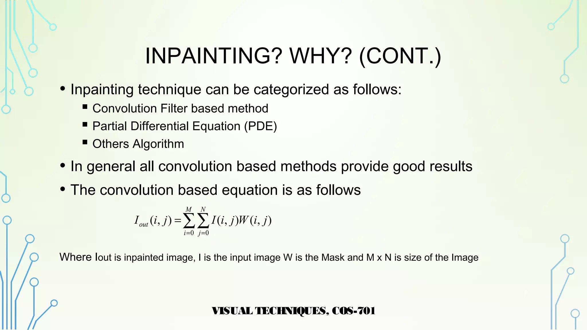
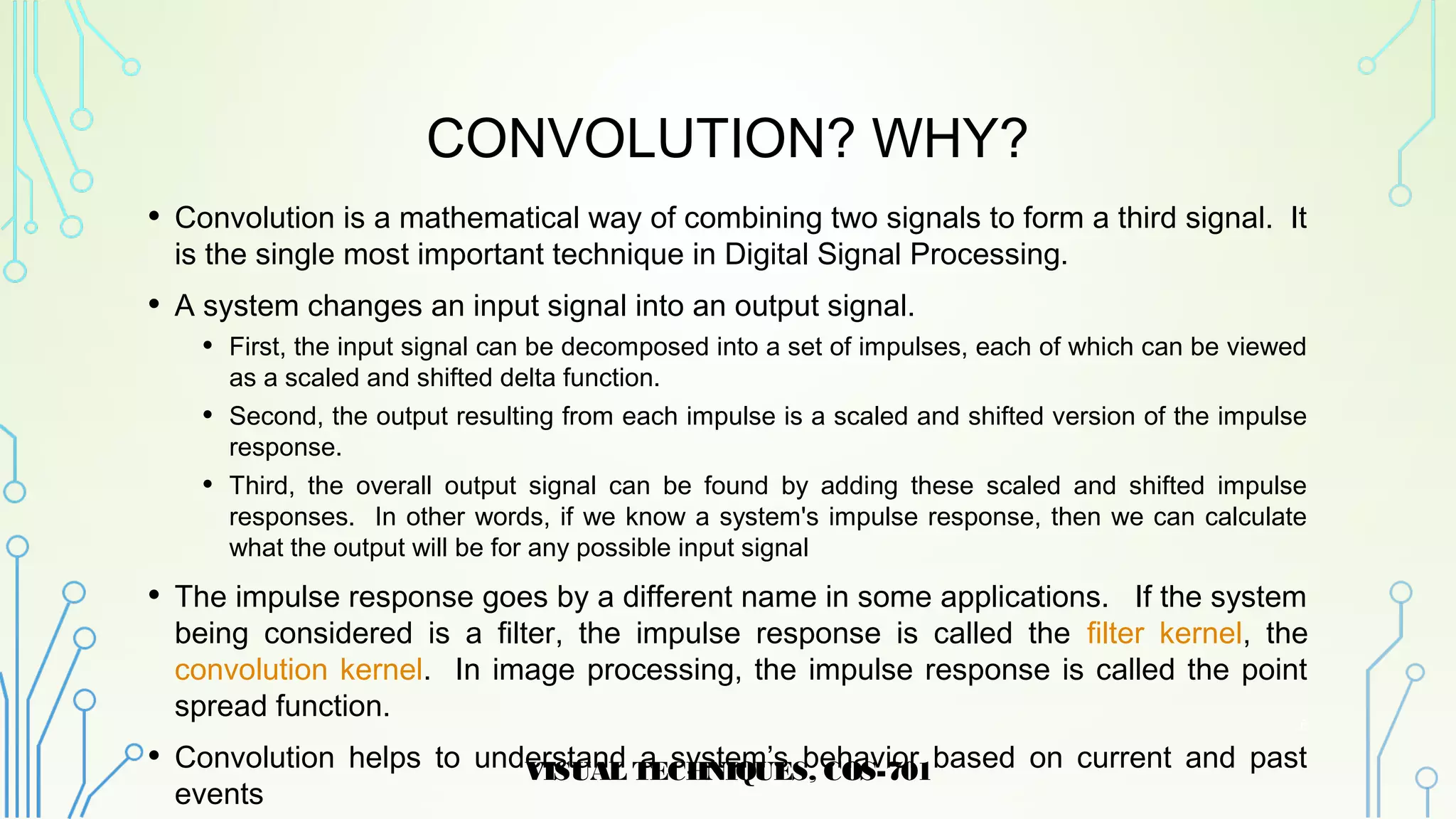
![CONVOLUTION? WHY? (CONT.)
• The below figure shows a simple convolution problem: a 9 point input
signal x[n] is passed through a system with a 4 point impulse response,
h[n], resulting in a 9+4-1=12 point output signal, y[n]. In mathematical
terms, x[n] is convolved with h[n] to produce y[n]. This first viewpoint of
convolution is based on the fundamental concept of DSP: decompose
the input, pass the components through the system, and synthesize the
output.
VISUAL TECHNIQUES, COS-701
7](https://image.slidesharecdn.com/deconvolutionondigitalimages-180412170933/75/De-convolution-on-Digital-Images-7-2048.jpg)
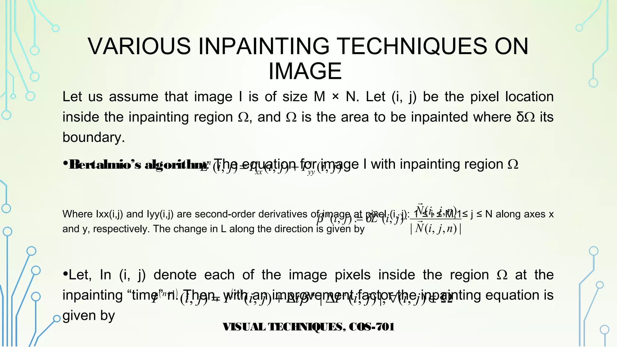
![VARIOUS INPAINTING TECHNIQUES ON
IMAGE
• Oliveira Algorithm: Proposed an inpainting algorithm deleting color
information inside the mask, followed by edge detection for the
occluded/damaged area. Starting from the pixels on the edge, a convolution
operation is then applied, using a neighborhood centered on each contour
pixel and one of the proposed kernels [3]-[5]
• Oliviera method takes the image to inpaint on selected region by convolving
with averaging filter has a zero weight at the center
Where the values of a, b, and c for both kernels are 0.073235, 0.176765, and 0.125 respectively
VISUAL TECHNIQUES, COS-701
10
∑∑
∑∑
= =
= =
=
=
M
i
N
j
out
M
i
N
j
jiWjiIjiI
jiWjiIjiI
0 0
/
0 0
/
),(2).,(),(
),(1).,(),(](https://image.slidesharecdn.com/deconvolutionondigitalimages-180412170933/75/De-convolution-on-Digital-Images-10-2048.jpg)
![VARIOUS INPAINTING TECHNIQUES ON
IMAGE (CONT.)
• Hadhoud, Moustafa, and Shenoda’s Algorithm: They have proposed an
improvement of Oliveira’s method with reducing processing time with convoluting
the region with averaging filter has a zero weight at bottom right corner instead of
center. [4]-[6]
• The method uses a differently defined convolution kernel by using more known
neighbors, and the restoration process can be achieved even within a single
iteration
Where the values of a, b, and c for both kernels are 0.073235, 0.176765, and 0.125
respectively
VISUAL TECHNIQUES, COS-701
11
∑∑
∑∑
= =
= =
=
=
M
i
N
j
out
M
i
N
j
jiWjiIjiI
jiWjiIjiI
0 0
/
0 0
/
),(2).,(),(
),(1).,(),(](https://image.slidesharecdn.com/deconvolutionondigitalimages-180412170933/75/De-convolution-on-Digital-Images-11-2048.jpg)
![VARIOUS INPAINTING TECHNIQUES ON
IMAGE (CONT.)
• H. Noori, S. Saryazdi, H. Nezamabadi: Uses an adaptive kernel permitting a better
processing edge regions. To do this, it uses the gradient of known pixels in the
neighborhood of a missed pixel to compute weights in convolving mask W(x) by
proposing a function F(x) to compute weights from the image gradient. [7]-[8]
• Selecting a missed pixel on boundary of the damaged region, next considering a
neighborhood around it and central gradients for each recognized pixel in the mask W(x),
is then calculated. Then finally, a value for a damaged pixel is calculated as
Where k presents the pixel position, x is gradient value of the current pixel in the image, α is a parameter
giving an estimation of the missed pixel gradient control the softness of propagation and f'(p) is estimated
value, f(k) is value of a known pixel, n is the number of known pixel in the current neighborhood.
VISUAL TECHNIQUES, COS-701
12
≥
≤≤−
≤−
=
α
α
α
α
α
α
||0
||
2
)1(
2
||)(1
)( 2
2
xif
xif
x
xif
x
xF
)(
1
)( kxF
n
xw =
)())()())(1()( 11
/
kfkwpfkwpf
n
k
n
k ∑∑ −−
+−=](https://image.slidesharecdn.com/deconvolutionondigitalimages-180412170933/75/De-convolution-on-Digital-Images-12-2048.jpg)
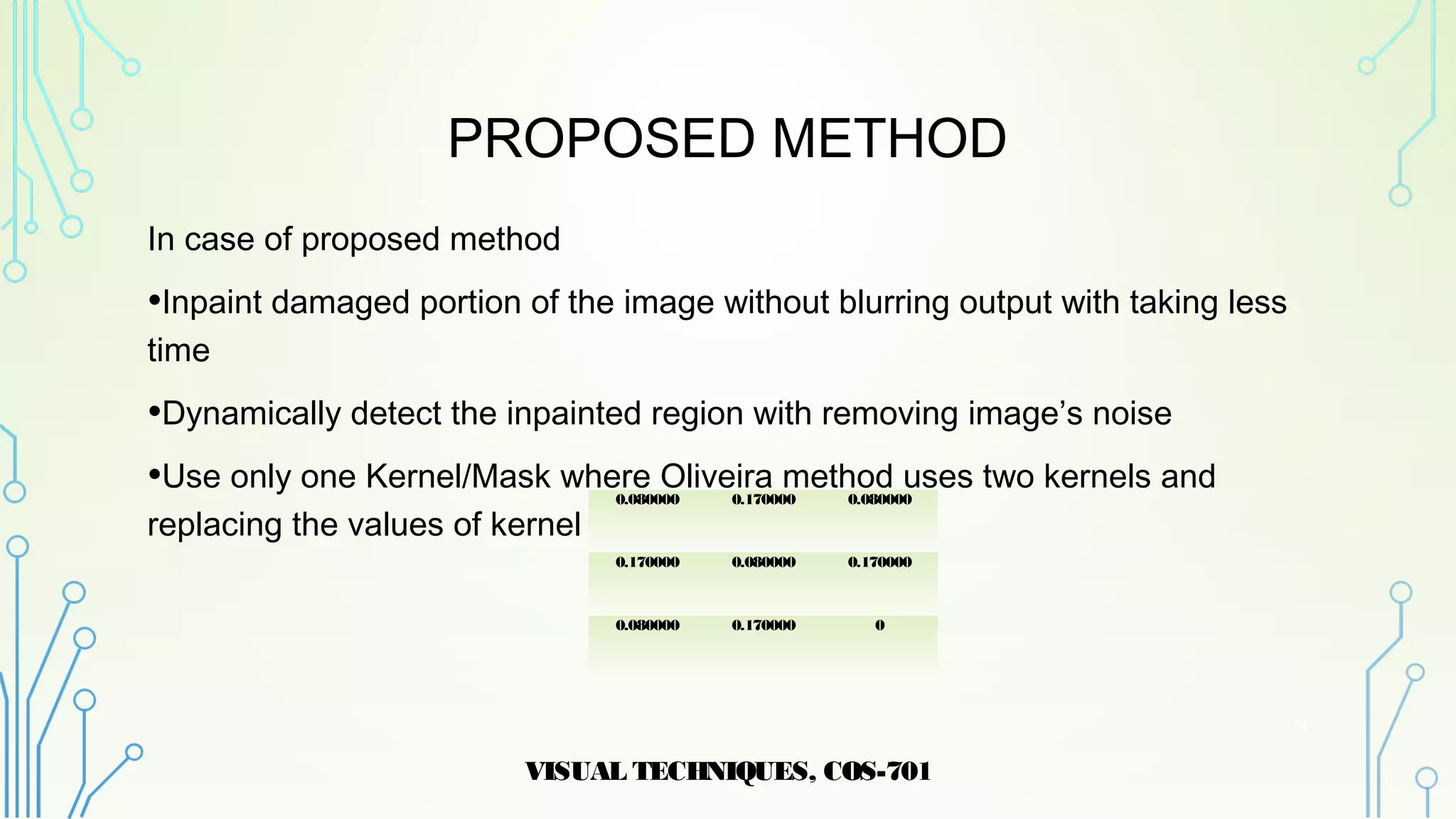
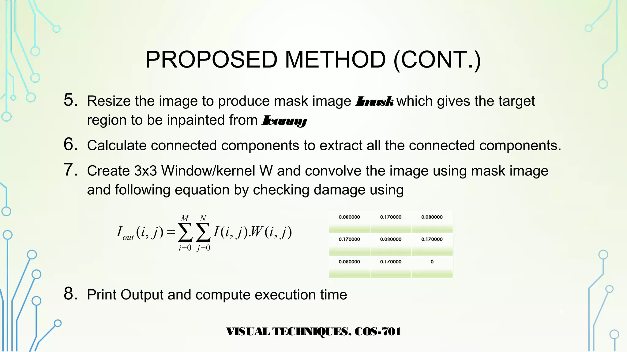
![PROPOSED METHOD (CONT.)
1. Input Image with damage information
2. Color Image Converted in to Gray scale
3. Filter the image to remove noise using median filter
4. Find edge of Imidusing “Canny Edge Detector” and smoothing image to
reduce the number of connected components producing Icanny
VISUAL TECHNIQUES, COS-701
15
)(
)(
]:1[]:1[
II
WI
W
sortmid
nsort
n
mid
sort
MNIF
=
=
=](https://image.slidesharecdn.com/deconvolutionondigitalimages-180412170933/75/De-convolution-on-Digital-Images-15-2048.jpg)
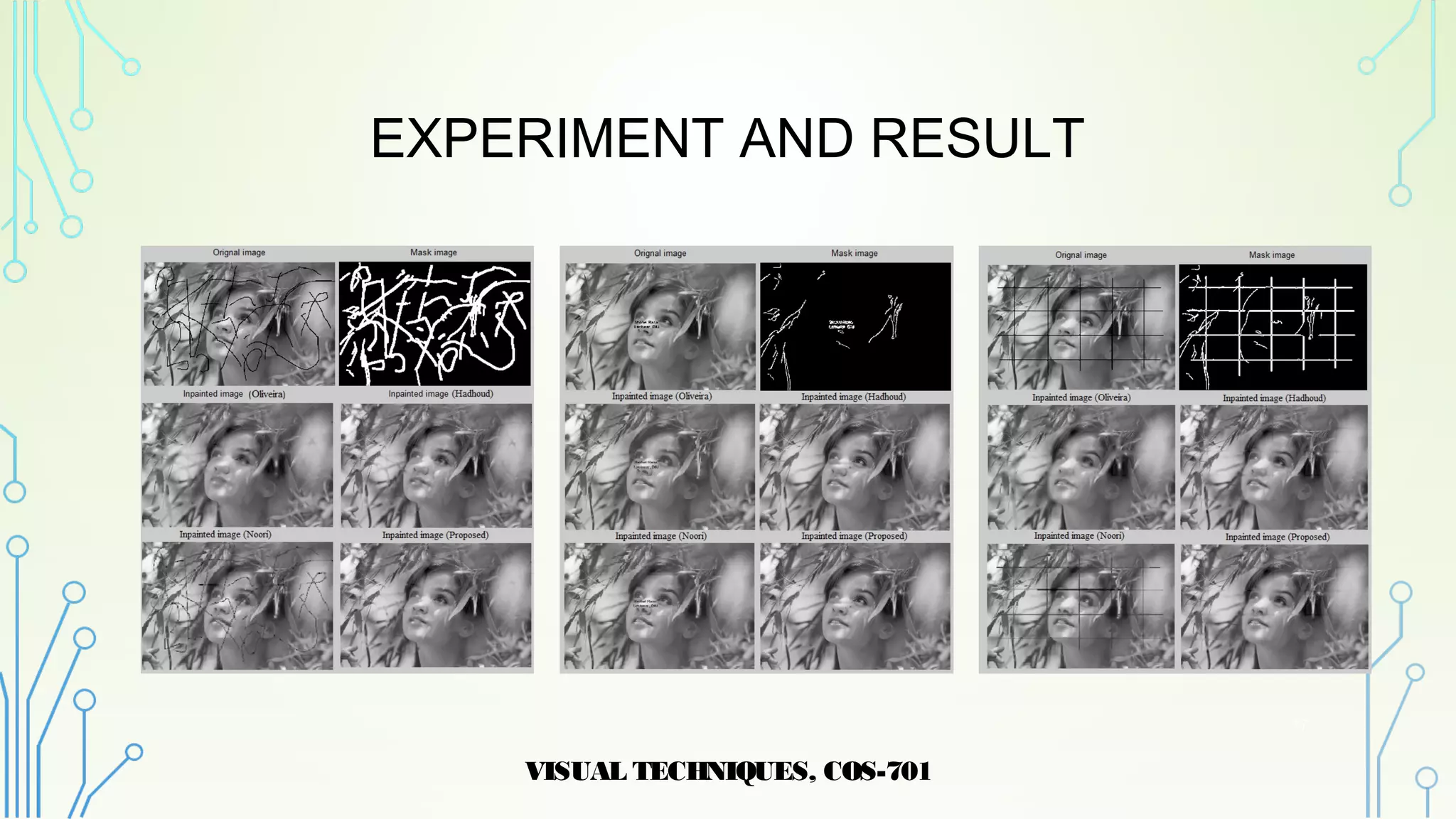


The document discusses inpainting, a technique for reconstructing damaged or missing areas in images, and presents various algorithms, including one developed by the author that reduces processing time and avoids image blurring. It reviews traditional and convolution-based methods, outlining their applications in image restoration. The proposed method demonstrates improved execution times and results, indicating its potential for future use in both 2D and 3D image processing.


![[IJET-V1I6P16] Authors : Indraja Mali , Saumya Saxena ,Padmaja Desai , Ajay G...](https://cdn.slidesharecdn.com/ss_thumbnails/ijet-v1i6p16-160110012011-thumbnail.jpg?width=640&height=640&fit=bounds)