International Islamic UniversityH-10, Islamabad, Pakistan
Database Management System
Week 04
Relational Model
Engr. Rashid Farid Chishti
http://youtube.com/rfchishti
http://sites.google.com/site/chisht
i
2.
Understand therelational model and its importance in DBMS
Learn key concepts like relational schema, keys, and constraints
Learning Objectives
3.
The RelationalModel is a way to structure and manage data in a database by
organizing it into tables (relations).
Converts the ER Diagram into tables (relations) with attributes.
It was introduced by E.F. Codd in 1970 and is the foundation of most modern
database systems.
Relational Model is the most widely used model.
In this model, the data is maintained in the form of a two-dimensional table.
All the information is stored in the form of row and columns.
The basic structure of a relational model is tables.
So, the tables are also called relations in the relational model.
What is a Relational Model ?
4.
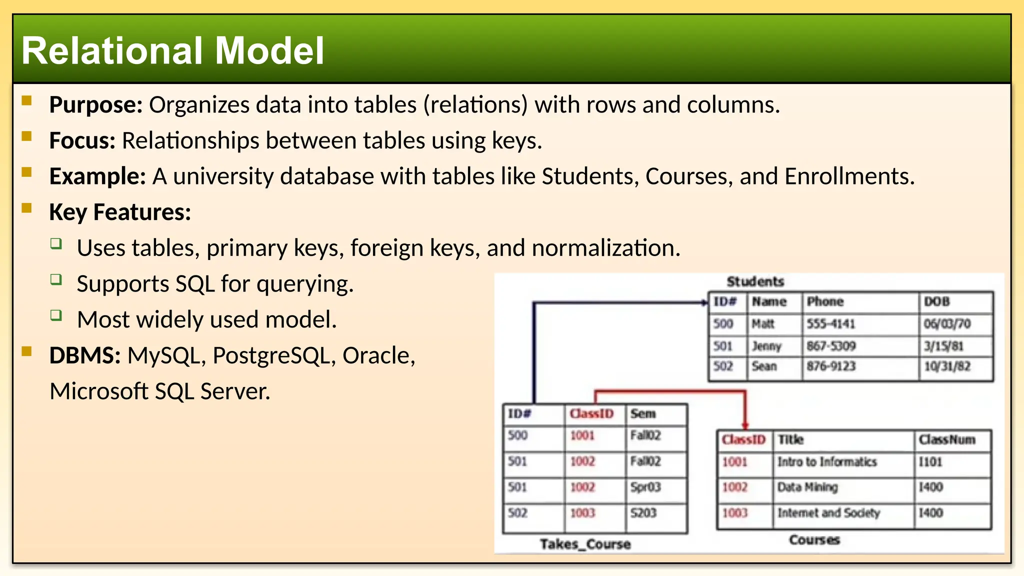
Purpose: Organizesdata into tables (relations) with rows and columns.
Focus: Relationships between tables using keys.
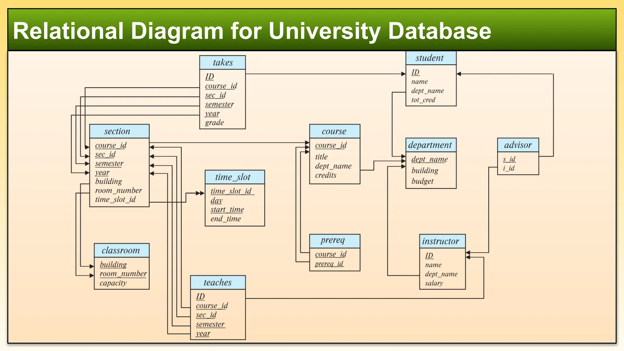
Example: A university database with tables like Students, Courses, and Enrollments.
Key Features:
Uses tables, primary keys, foreign keys, and normalization.
Supports SQL for querying.
Most widely used model.
DBMS: MySQL, PostgreSQL, Oracle,
Microsoft SQL Server.
Relational Model
5.
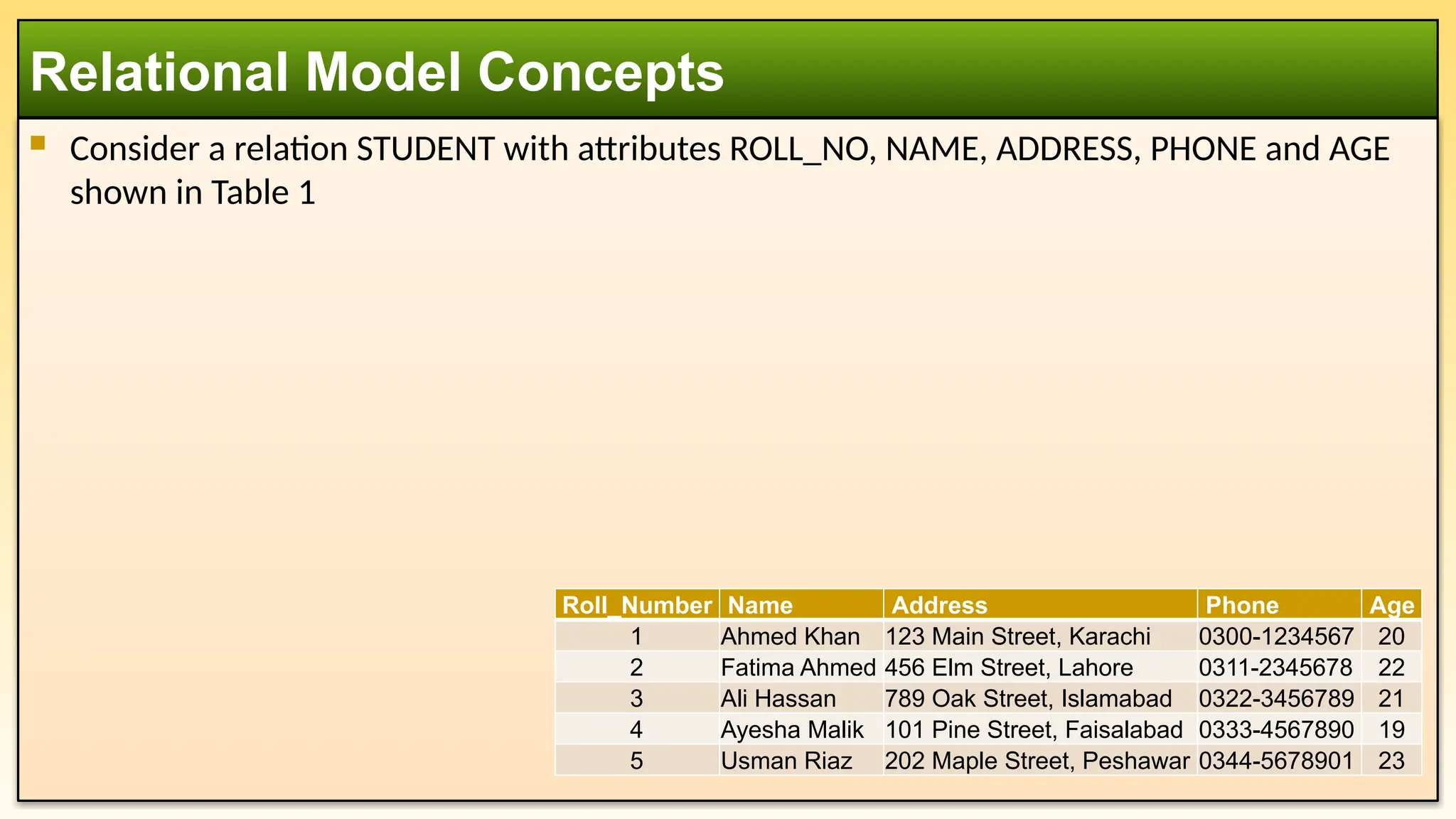
Consider arelation STUDENT with attributes ROLL_NO, NAME, ADDRESS, PHONE and AGE
shown in Table 1
Relational Model Concepts
Roll_Number Name Address Phone Age
1 Ahmed Khan 123 Main Street, Karachi 0300-1234567 20
2 Fatima Ahmed 456 Elm Street, Lahore 0311-2345678 22
3 Ali Hassan 789 Oak Street, Islamabad 0322-3456789 21
4 Ayesha Malik 101 Pine Street, Faisalabad 0333-4567890 19
5 Usman Riaz 202 Maple Street, Peshawar 0344-5678901 23
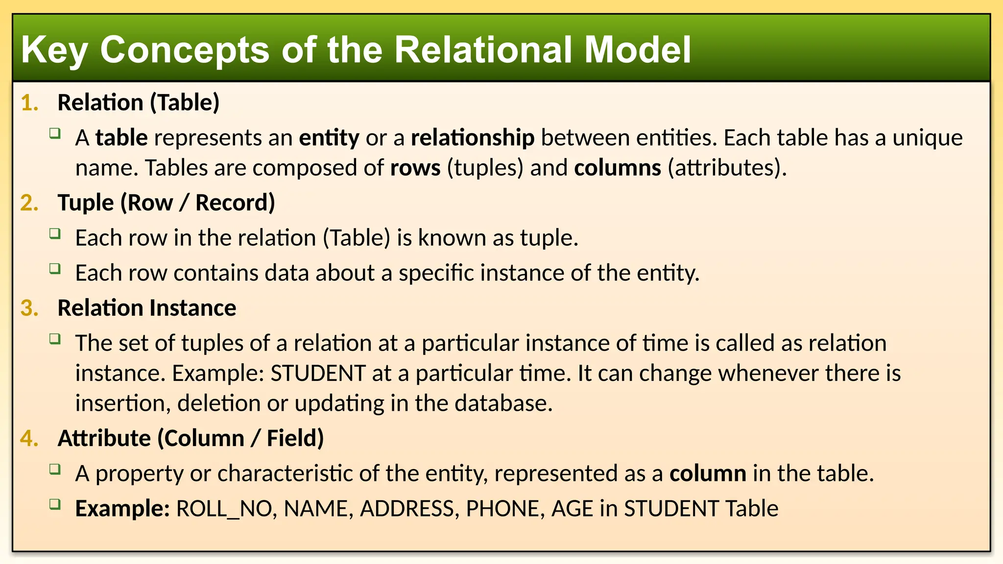
1. Relation (Table)
A table represents an entity or a relationship between entities. Each table has a unique
name. Tables are composed of rows (tuples) and columns (attributes).
2. Tuple (Row / Record)
Each row in the relation (Table) is known as tuple.
Each row contains data about a specific instance of the entity.
3. Relation Instance
The set of tuples of a relation at a particular instance of time is called as relation
instance. Example: STUDENT at a particular time. It can change whenever there is
insertion, deletion or updating in the database.
4. Attribute (Column / Field)
A property or characteristic of the entity, represented as a column in the table.
Example: ROLL_NO, NAME, ADDRESS, PHONE, AGE in STUDENT Table
Key Concepts of the Relational Model
8.
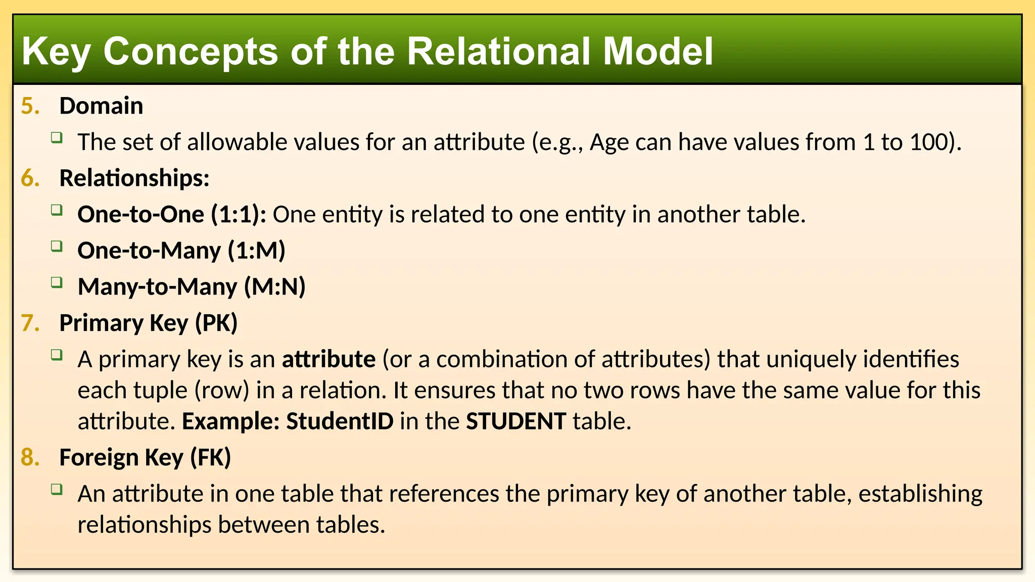
5. Domain
Theset of allowable values for an attribute (e.g., Age can have values from 1 to 100).
6. Relationships:
One-to-One (1:1): One entity is related to one entity in another table.
One-to-Many (1:M)
Many-to-Many (M:N)
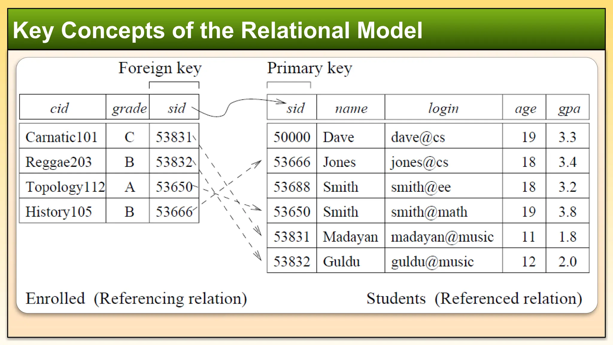
7. Primary Key (PK)
A primary key is an attribute (or a combination of attributes) that uniquely identifies
each tuple (row) in a relation. It ensures that no two rows have the same value for this
attribute. Example: StudentID in the STUDENT table.
8. Foreign Key (FK)
An attribute in one table that references the primary key of another table, establishing
relationships between tables.
Key Concepts of the Relational Model
9.
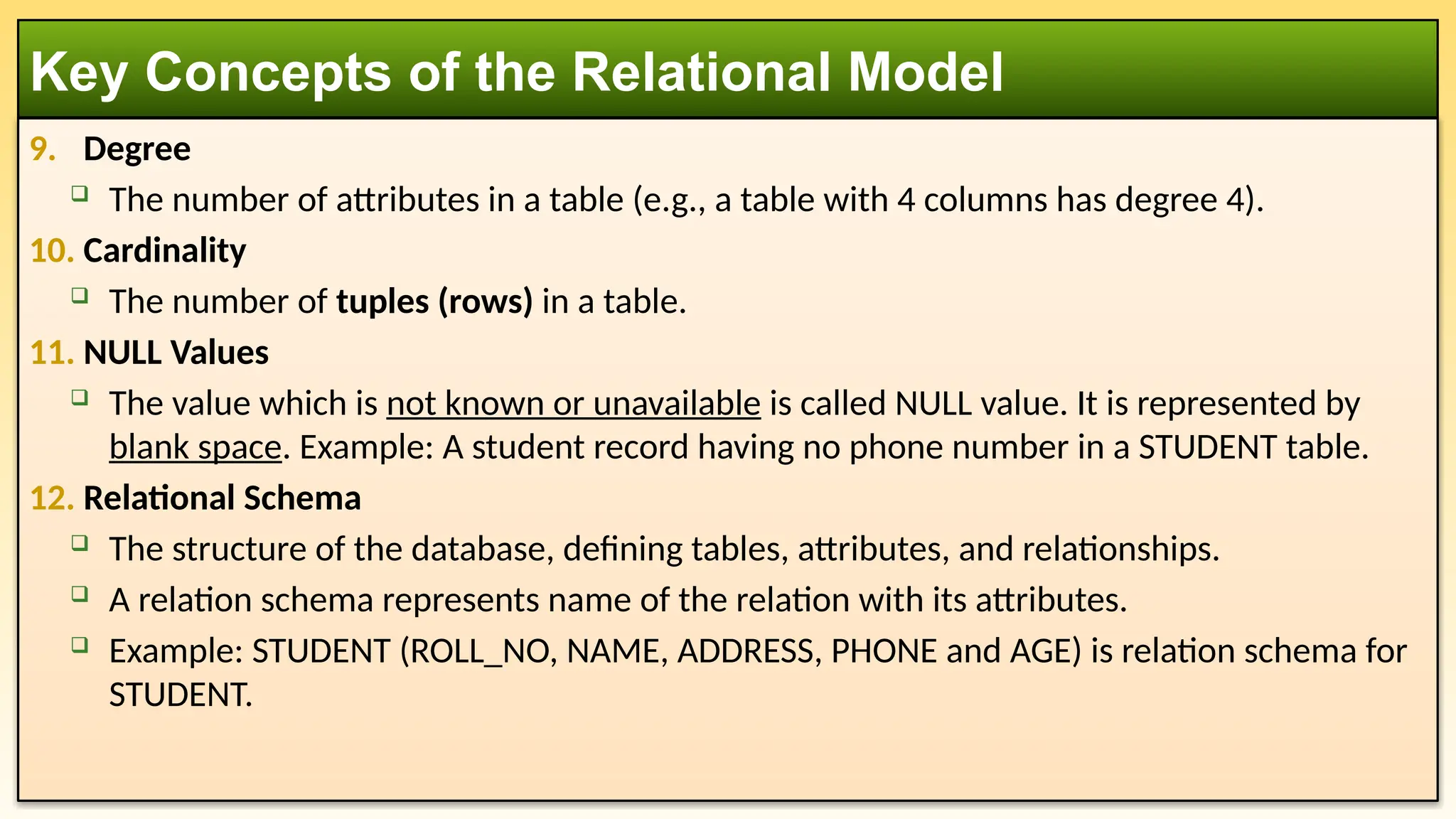
9. Degree
Thenumber of attributes in a table (e.g., a table with 4 columns has degree 4).
10. Cardinality
The number of tuples (rows) in a table.
11. NULL Values
The value which is not known or unavailable is called NULL value. It is represented by
blank space. Example: A student record having no phone number in a STUDENT table.
12. Relational Schema
The structure of the database, defining tables, attributes, and relationships.
A relation schema represents name of the relation with its attributes.
Example: STUDENT (ROLL_NO, NAME, ADDRESS, PHONE and AGE) is relation schema for
STUDENT.
Key Concepts of the Relational Model
10.
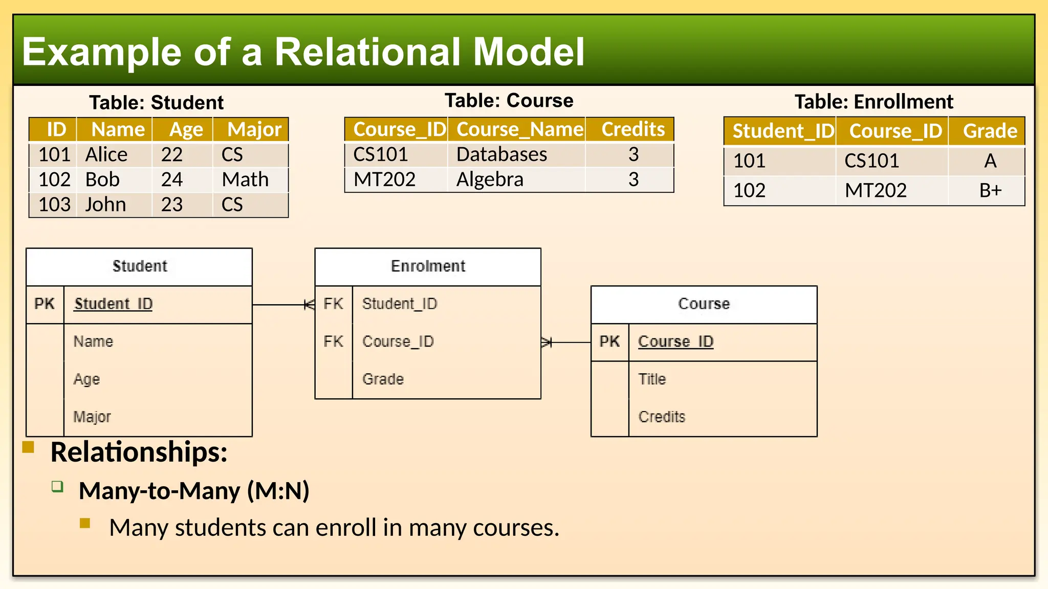
Relationships:
Many-to-Many(M:N)
Many students can enroll in many courses.
Example of a Relational Model
ID Name Age Major
101 Alice 22 CS
102 Bob 24 Math
103 John 23 CS
Course_ID Course_Name Credits
CS101 Databases 3
MT202 Algebra 3
Table: Student Table: Course
Student_ID Course_ID Grade
101 CS101 A
102 MT202 B+
Table: Enrollment
11.
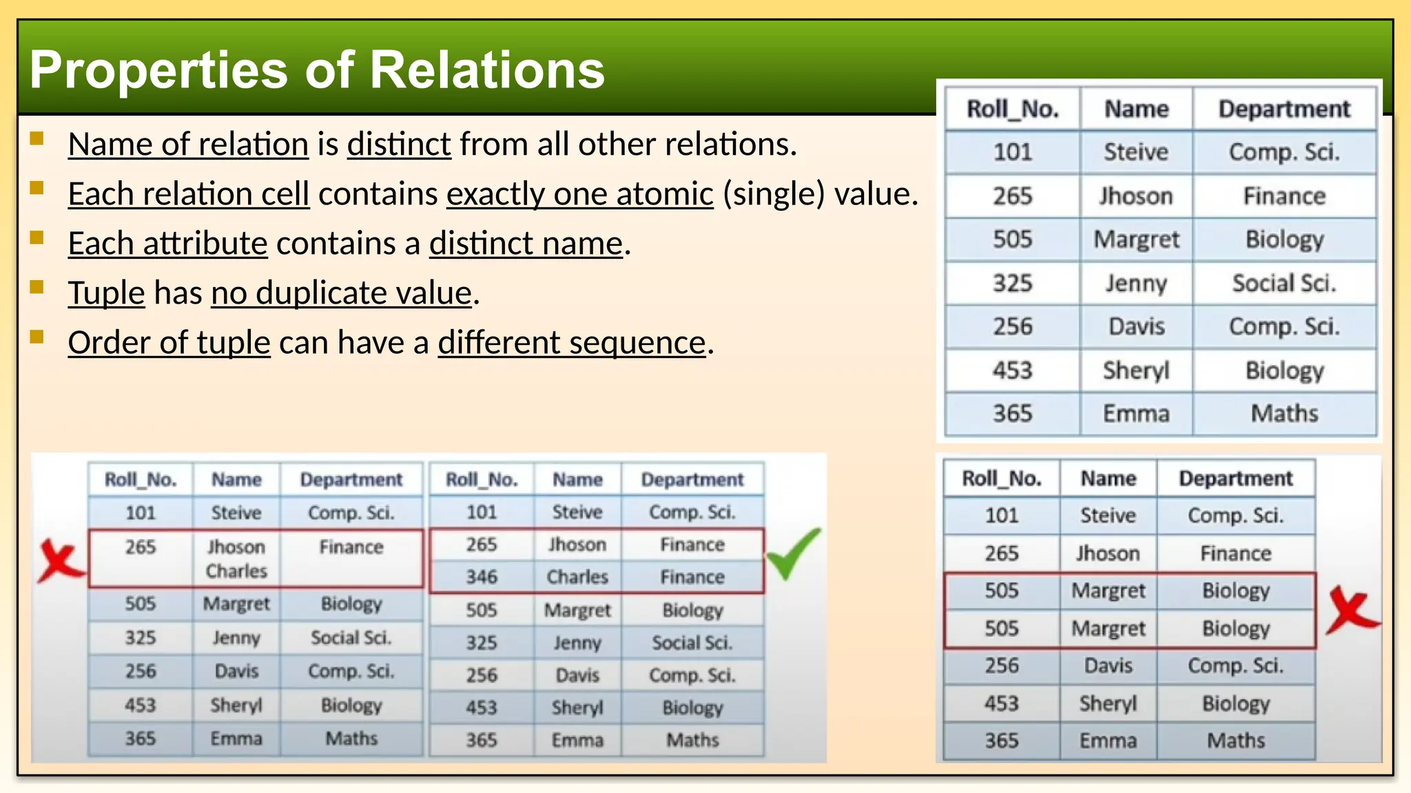
Name ofrelation is distinct from all other relations.
Each relation cell contains exactly one atomic (single) value.
Each attribute contains a distinct name.
Tuple has no duplicate value.
Order of tuple can have a different sequence.
Properties of Relations
12.
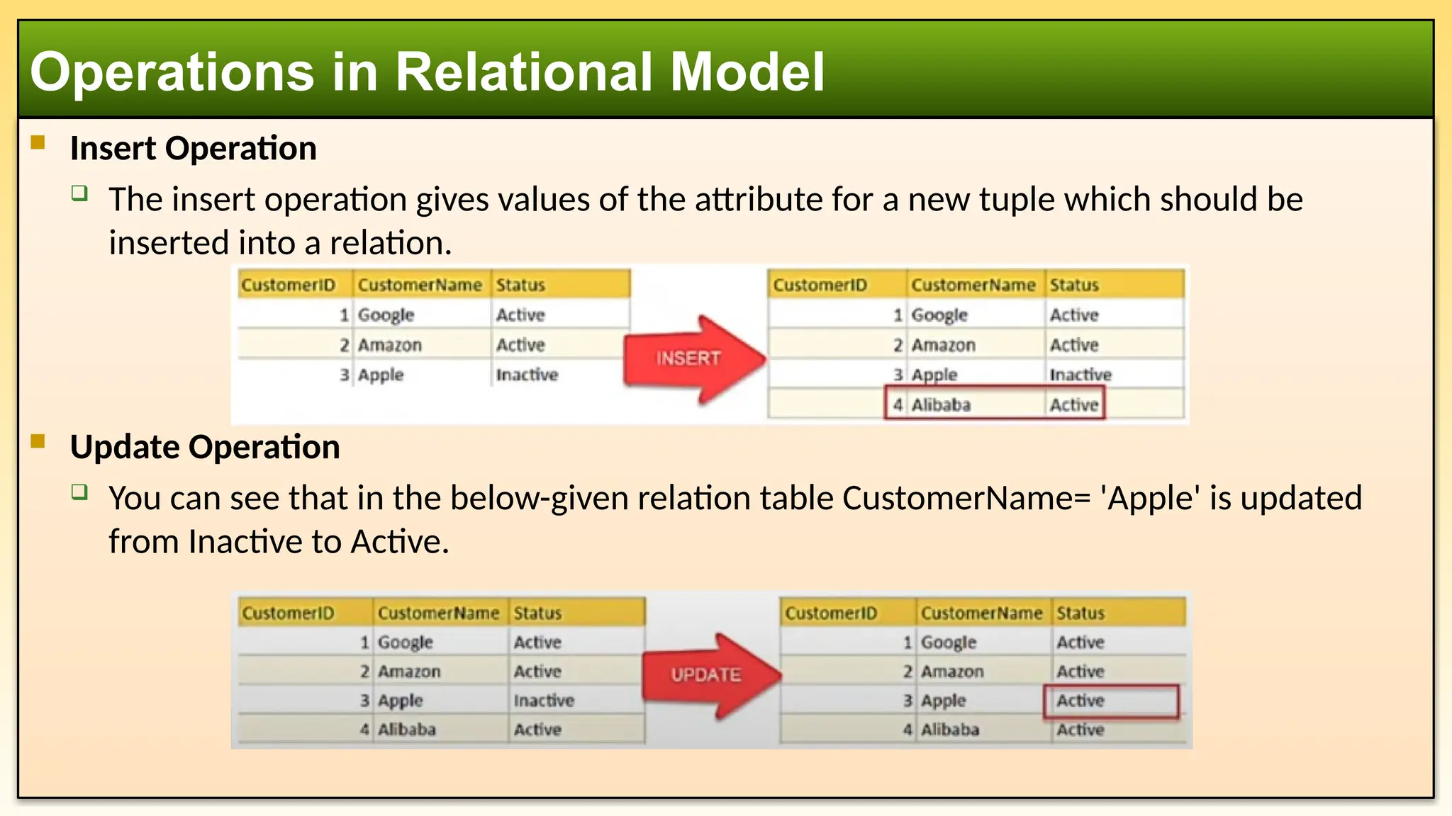
Insert Operation
The insert operation gives values of the attribute for a new tuple which should be
inserted into a relation.
Update Operation
You can see that in the below-given relation table CustomerName= 'Apple' is updated
from Inactive to Active.
Operations in Relational Model
13.
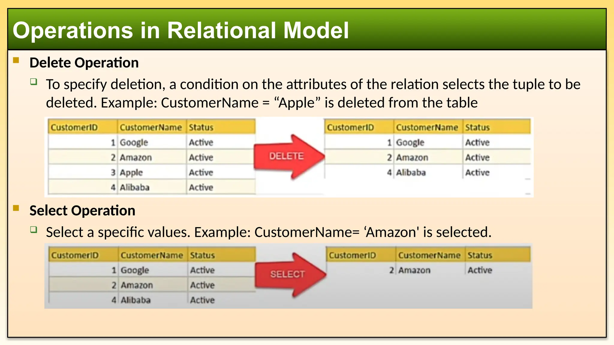
Delete Operation
To specify deletion, a condition on the attributes of the relation selects the tuple to be
deleted. Example: CustomerName = “Apple” is deleted from the table
Select Operation
Select a specific values. Example: CustomerName= ‘Amazon' is selected.
Operations in Relational Model
14.
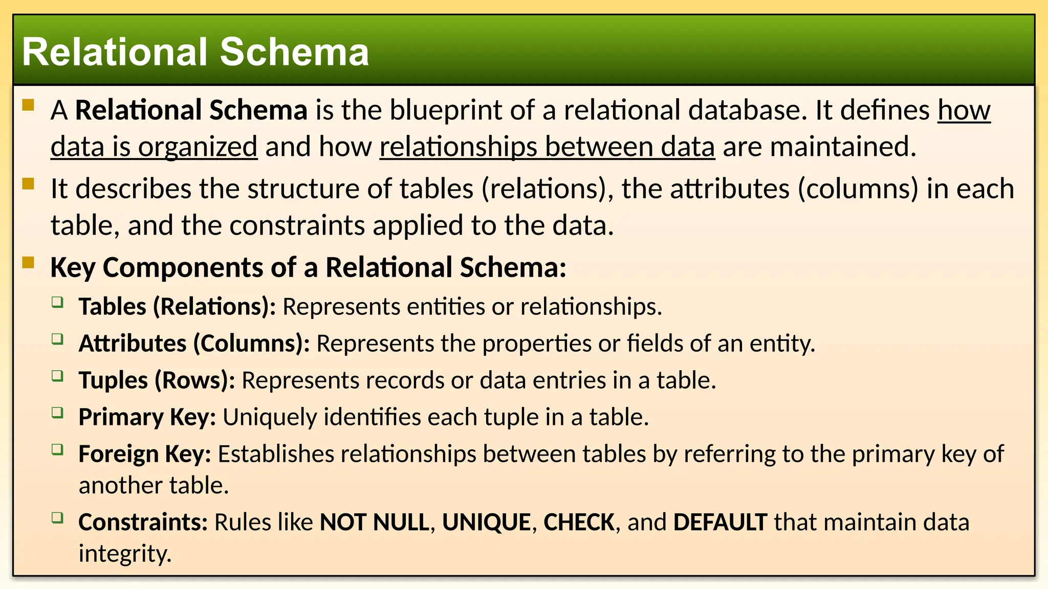
A RelationalSchema is the blueprint of a relational database. It defines how
data is organized and how relationships between data are maintained.
It describes the structure of tables (relations), the attributes (columns) in each
table, and the constraints applied to the data.
Key Components of a Relational Schema:
Tables (Relations): Represents entities or relationships.
Attributes (Columns): Represents the properties or fields of an entity.
Tuples (Rows): Represents records or data entries in a table.
Primary Key: Uniquely identifies each tuple in a table.
Foreign Key: Establishes relationships between tables by referring to the primary key of
another table.
Constraints: Rules like NOT NULL, UNIQUE, CHECK, and DEFAULT that maintain data
integrity.
Relational Schema
15.
Imagine auniversity database with two entities: Students and Courses.
Relational Schema:
Customer(ID, Name, Phone, Address)
Product(ID, Quantity, Product_Type)
Order(Customer_ID, Product_ID, Order_Date, Order_Status)
Relational Schema: Example
Customer
PK ID
Name
Phone
Address
Product
PK ID
Quantity
Product_Type
Order
FK Customer_ID
FK Product_ID
Order_Date
Order_Status
16.
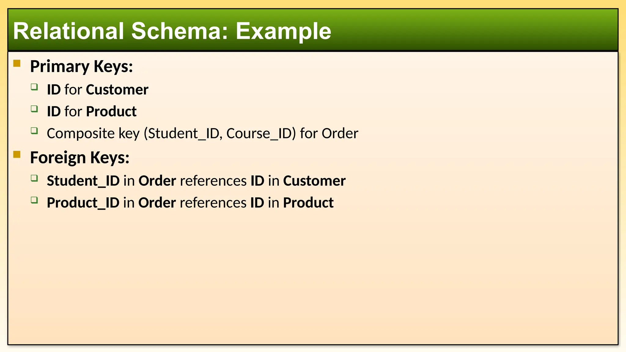
Primary Keys:
ID for Customer
ID for Product
Composite key (Student_ID, Course_ID) for Order
Foreign Keys:
Student_ID in Order references ID in Customer
Product_ID in Order references ID in Product
Relational Schema: Example
17.
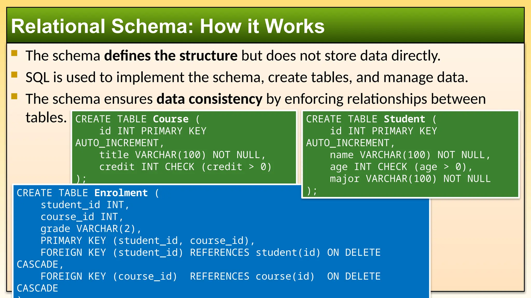
The schemadefines the structure but does not store data directly.
SQL is used to implement the schema, create tables, and manage data.
The schema ensures data consistency by enforcing relationships between
tables.
Relational Schema: How it Works
CREATE TABLE Course (
id INT PRIMARY KEY
AUTO_INCREMENT,
title VARCHAR(100) NOT NULL,
credit INT CHECK (credit > 0)
);
CREATE TABLE Enrolment (
student_id INT,
course_id INT,
grade VARCHAR(2),
PRIMARY KEY (student_id, course_id),
FOREIGN KEY (student_id) REFERENCES student(id) ON DELETE
CASCADE,
FOREIGN KEY (course_id) REFERENCES course(id) ON DELETE
CASCADE
CREATE TABLE Student (
id INT PRIMARY KEY
AUTO_INCREMENT,
name VARCHAR(100) NOT NULL,
age INT CHECK (age > 0),
major VARCHAR(100) NOT NULL
);
18.
Example DataInsertion:
Query Example:
Relational Schema: How it Works
SELECT s.Name, c.Title, e.Grade
FROM Student s
JOIN Enrolment e ON e.student_id = s.id
JOIN Course c ON c.id = e.course_id;
INSERT INTO Student VALUES (101, 'Alice Johnson', 20, 'Computer
Science');
INSERT INTO Course VALUES (301, 'Database Systems', 3);
INSERT INTO Enrolment VALUES (101, 301, 'B+');
19.
Comparison of threeModels
Feature ER Model Relational Model Relational Schema
Purpose Conceptual design of data Logical structure of data
Physical blueprint for database
implementation
Focus
Entities, attributes, and
relationships
Tables (relations), rows (tuples),
and columns (attributes)
Table structures, columns, and
constraints
Representation
ER Diagrams (Entities,
Relationships)
Relations (Tables) Table definitions with attributes
Abstraction
Level High-level Mid-level Low-level
Design Stage
Early stage (Conceptual
design)
Intermediate stage (Logical
design)
Final stage (Physical
implementation)
Used By Database designers Database architects
Database developers (SQL
coders)
Use Case
Planning and early-stage
design.
Conceptualizing and structuring
data. Defining tables for the DBMS.
20.
Levels of Abstraction
FeatureER Model Relational Model Relational Schema
Entity Names ✔ ✔
Attributes ✔ ✔
Entity Relationships ✔ ✔
Primary Keys ✔ ✔ ✔
Foreign Keys ✔ ✔
Tables Names ✔
Column Names ✔
Column Data Types ✔
21.
1. Startwith ER Model (Conceptual Design):
Identify entities, attributes, and relationships.
Create an ER diagram representing the high-level structure.
2. Convert to Relational Model (Logical Design):
Translate ER diagrams into tables, keys, and relationships.
3. Implement Relational Schema (Physical Design):
Define SQL CREATE TABLE statements to implement the tables and constraints in the
database.
How They Fit Together in Database Design:
22.
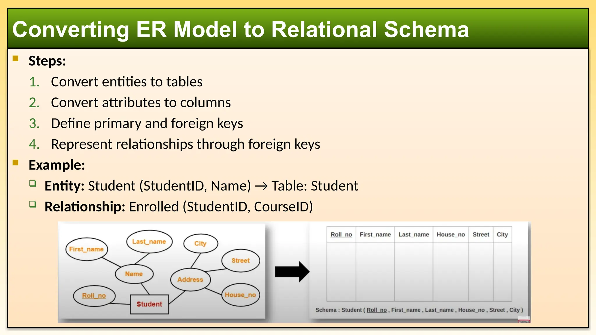
Steps:
1. Convertentities to tables
2. Convert attributes to columns
3. Define primary and foreign keys
4. Represent relationships through foreign keys
Example:
Entity: Student (StudentID, Name) → Table: Student
Relationship: Enrolled (StudentID, CourseID)
Converting ER Model to Relational Schema
23.
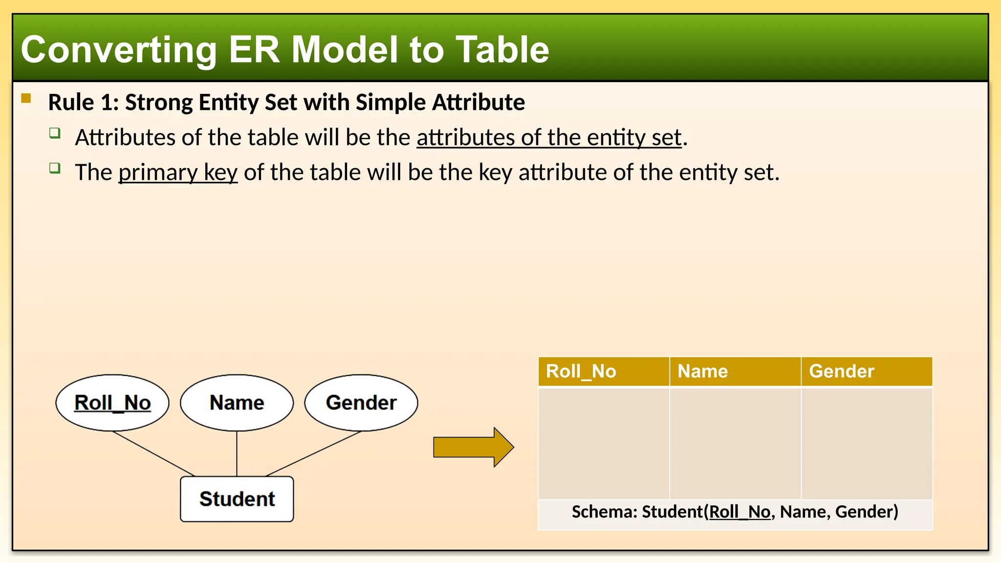
Rule 1:Strong Entity Set with Simple Attribute
Attributes of the table will be the attributes of the entity set.
The primary key of the table will be the key attribute of the entity set.
Converting ER Model to Table
Roll_No Name Gender
Schema: Student(Roll_No, Name, Gender)
24.
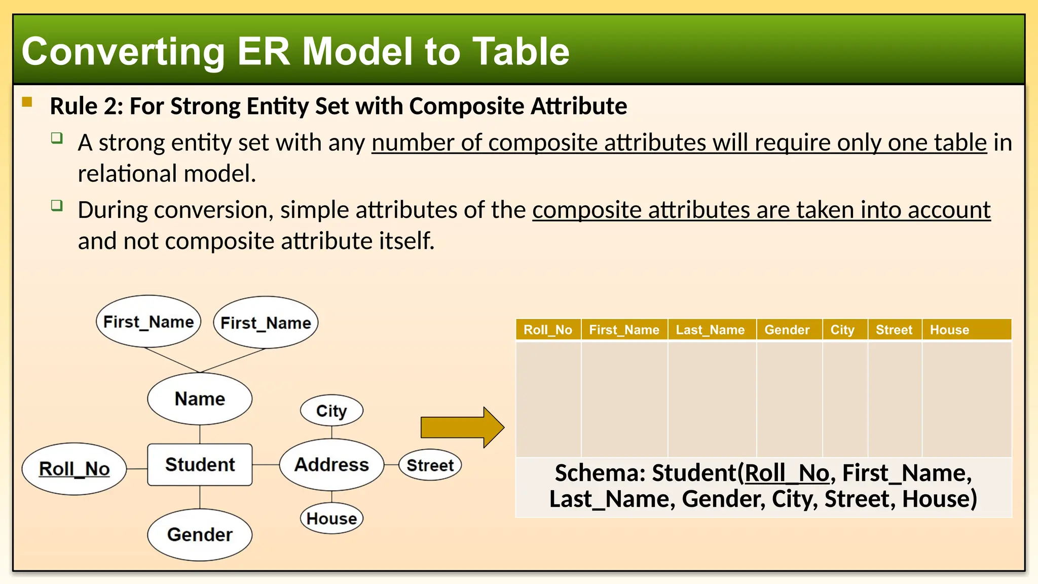
Rule 2:For Strong Entity Set with Composite Attribute
A strong entity set with any number of composite attributes will require only one table in
relational model.
During conversion, simple attributes of the composite attributes are taken into account
and not composite attribute itself.
Converting ER Model to Table
Roll_No First_Name Last_Name Gender City Street House
Schema: Student(Roll_No, First_Name,
Last_Name, Gender, City, Street, House)
25.
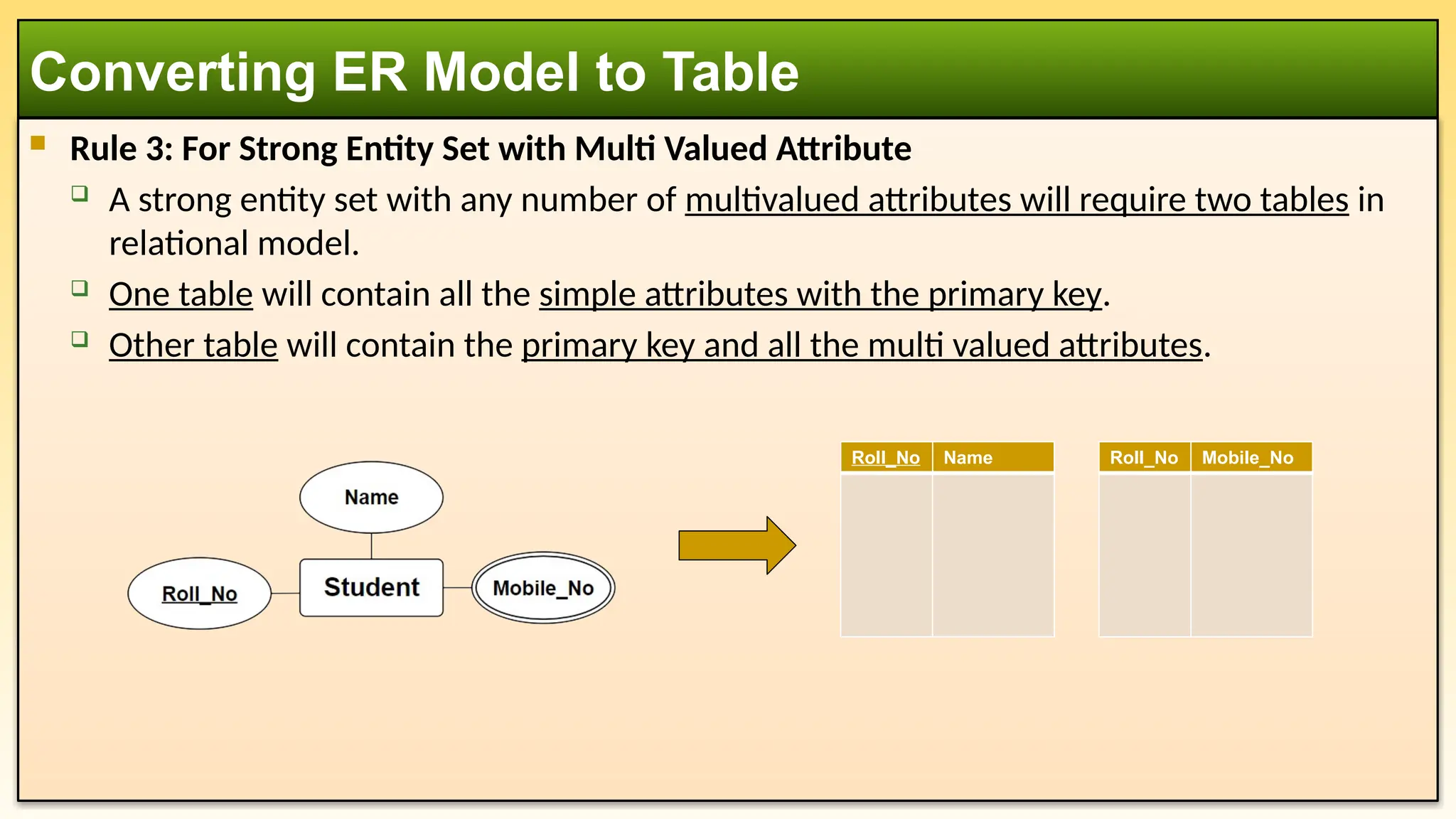
Rule 3:For Strong Entity Set with Multi Valued Attribute
A strong entity set with any number of multivalued attributes will require two tables in
relational model.
One table will contain all the simple attributes with the primary key.
Other table will contain the primary key and all the multi valued attributes.
Converting ER Model to Table
Roll_No Name Roll_No Mobile_No
26.
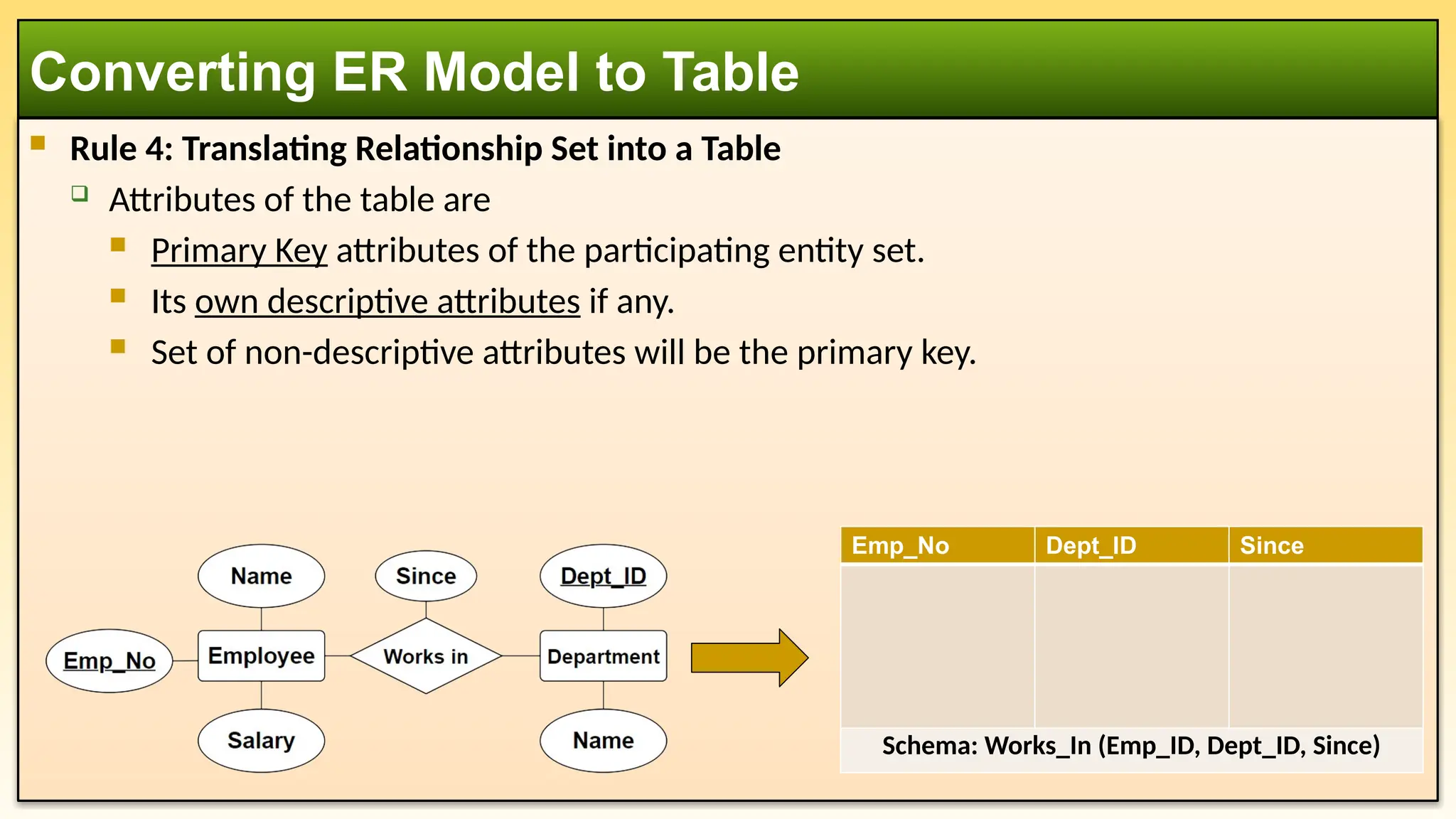
Rule 4:Translating Relationship Set into a Table
Attributes of the table are
Primary Key attributes of the participating entity set.
Its own descriptive attributes if any.
Set of non-descriptive attributes will be the primary key.
Converting ER Model to Table
Emp_No Dept_ID Since
Schema: Works_In (Emp_ID, Dept_ID, Since)
27.
The RelationalModel in databases offers several advantages, making it a widely used and
preferred approach for data management. Here are some key benefits:
Simplicity & Ease of Use
Uses tables (relations), which are intuitive and easy to understand.
Data is represented in rows and columns, making it straightforward to query and
manipulate.
Structural Independence
Changes in database schema (such as adding or modifying columns) do not affect
applications using the database.
Provides flexibility in evolving the database structure.
Data Integrity & Accuracy
Supports integrity constraints (e.g., primary keys, foreign keys, and unique constraints) to
maintain data consistency. Ensures referential integrity, preventing orphan records and
maintaining valid relationships.
Advantages of using Relational Model
28.
Reduced DataRedundancy
Normalization techniques eliminate data duplication, improving storage efficiency.
Reducing redundancy helps maintain consistency across records.
Data Security
Provides access control mechanisms, ensuring only authorized users can access or
modify data. Allows implementation of different privileges for different users.
Flexibility in Querying (SQL Support)
Supports Structured Query Language (SQL), which enables complex queries, filtering, and
data manipulation. SQL makes it easier to retrieve and update data efficiently.
Multi-User Support & Concurrency Control
Allows multiple users to access and manipulate the database simultaneously.
Implements transactions with ACID (Atomicity, Consistency, Isolation, Durability)
properties, ensuring reliability.
Advantages of using Relational Model
29.
Data Consistency
Enforces constraints and rules to maintain correct and reliable data.
Ensures that changes made by one user do not negatively impact others.
Scalability & Performance Optimization
Can handle large datasets and complex relationships efficiently.
Indexing, query optimization, and partitioning techniques enhance performance.
Standardization & Portability
Relational databases follow ANSI/ISO standards, making them compatible across
different platforms.
Popular RDBMSs like MySQL, PostgreSQL, Oracle, and SQL Server support the relational
model, ensuring widespread adoption.
Advantages of using Relational Model
30.
1. Complexity& Performance Overhead
Requires complex schema design (e.g., normalization) to ensure efficiency.
Queries involving multiple joins can be slow and resource-intensive.
Performance may degrade for large-scale applications with millions of transactions.
2. Storage & Hardware Requirements
Requires more storage space due to indexes, constraints, and relationships.
High-performance relational databases may need powerful hardware for efficient
operations.
3. Scalability Challenges
Vertical Scaling (adding more resources to a single server) is common but has limits.
Horizontal Scaling (distributing data across multiple servers) is complex compared to
NoSQL databases.
Disadvantages of using Relational Model
31.
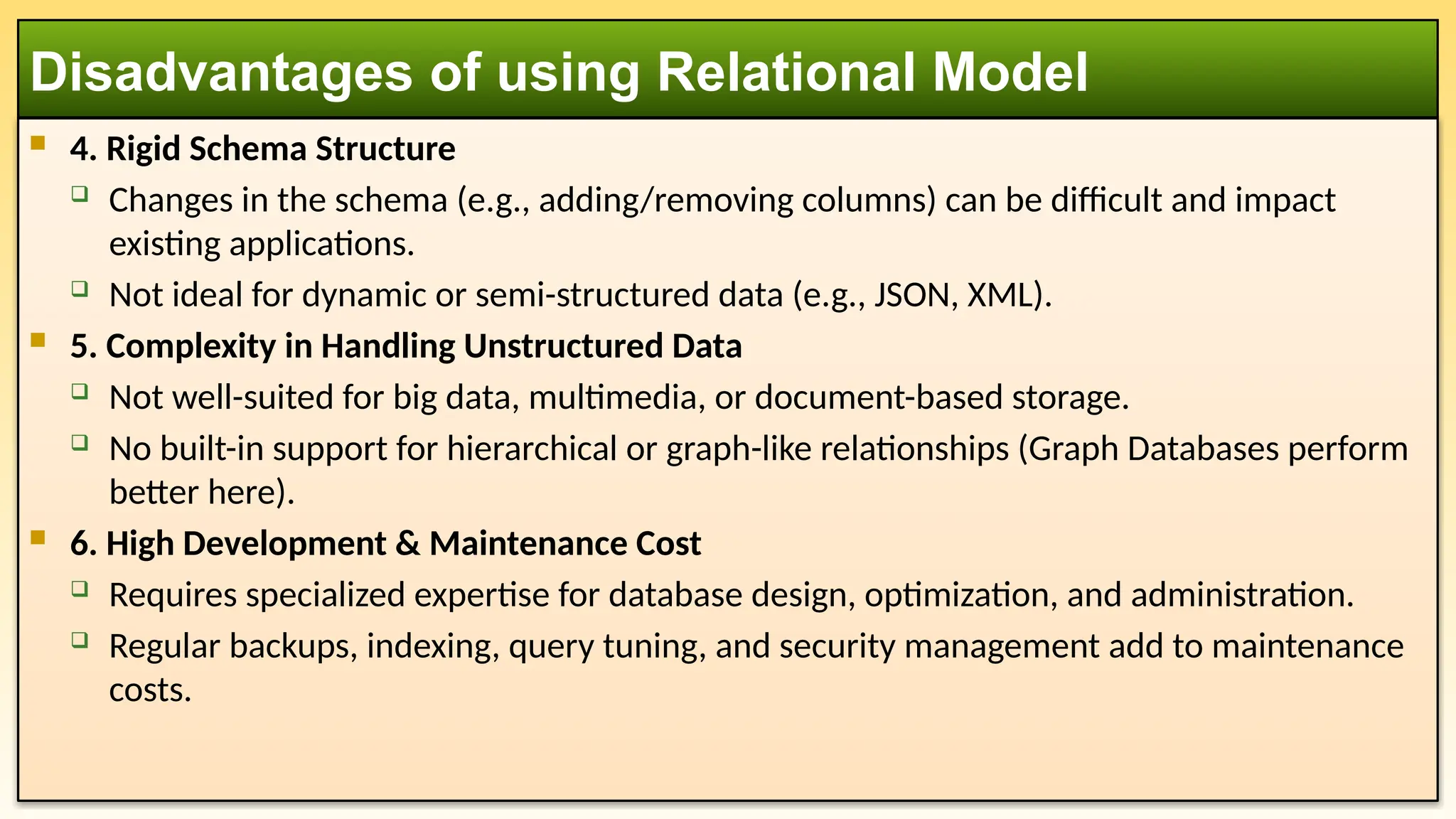
4. RigidSchema Structure
Changes in the schema (e.g., adding/removing columns) can be difficult and impact
existing applications.
Not ideal for dynamic or semi-structured data (e.g., JSON, XML).
5. Complexity in Handling Unstructured Data
Not well-suited for big data, multimedia, or document-based storage.
No built-in support for hierarchical or graph-like relationships (Graph Databases perform
better here).
6. High Development & Maintenance Cost
Requires specialized expertise for database design, optimization, and administration.
Regular backups, indexing, query tuning, and security management add to maintenance
costs.
Disadvantages of using Relational Model
32.
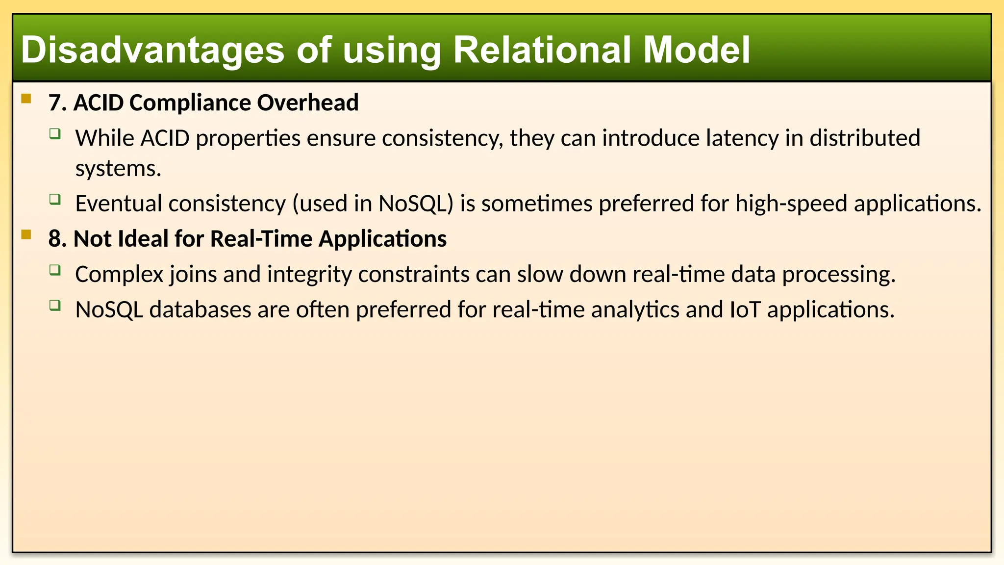
7. ACIDCompliance Overhead
While ACID properties ensure consistency, they can introduce latency in distributed
systems.
Eventual consistency (used in NoSQL) is sometimes preferred for high-speed applications.
8. Not Ideal for Real-Time Applications
Complex joins and integrity constraints can slow down real-time data processing.
NoSQL databases are often preferred for real-time analytics and IoT applications.
Disadvantages of using Relational Model
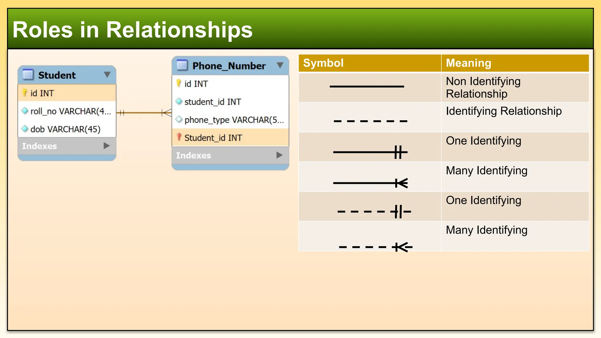
Roles in Relationships
SymbolMeaning
Non Identifying
Relationship
Identifying Relationship
One Identifying
Many Identifying
One Identifying
Many Identifying
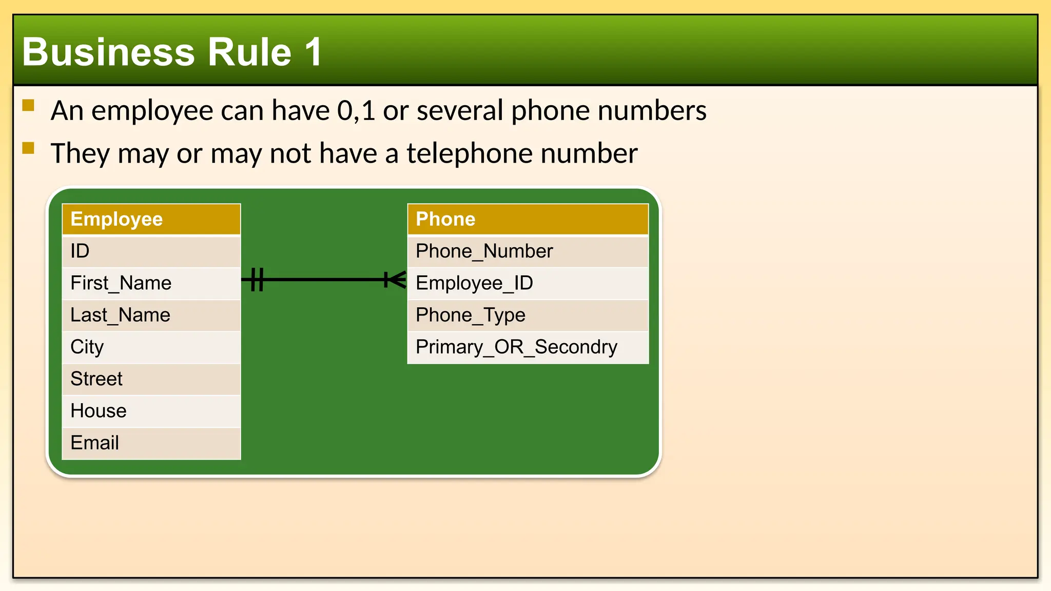
An employeecan have 0,1 or several phone numbers
They may or may not have a telephone number
Business Rule 1
Phone
Phone_Number
Employee_ID
Phone_Type
Primary_OR_Secondry
Employee
ID
First_Name
Last_Name
City
Street
House
Email
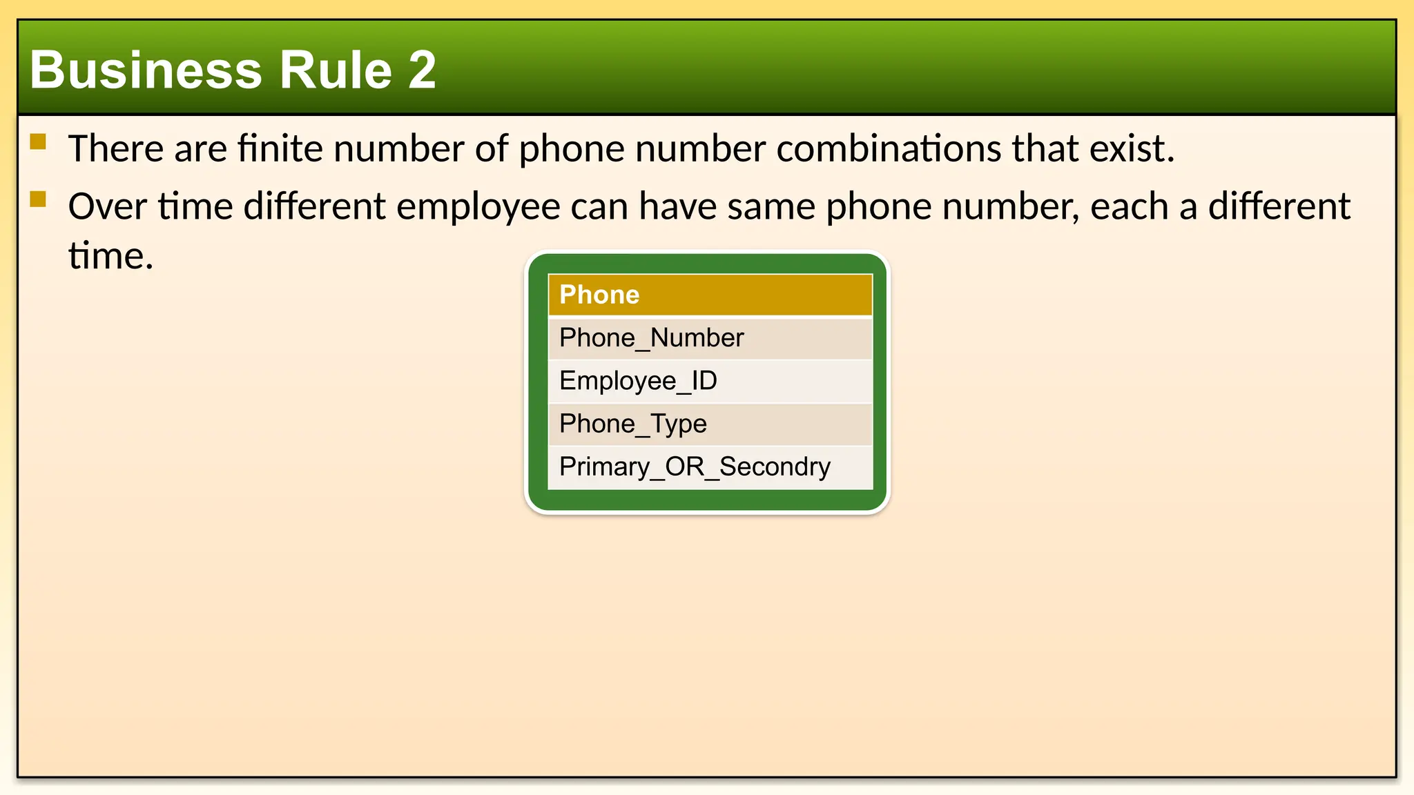
38.
There arefinite number of phone number combinations that exist.
Over time different employee can have same phone number, each a different
time.
Business Rule 2
Phone
Phone_Number
Employee_ID
Phone_Type
Primary_OR_Secondry
39.
An employeecan be paid either hourly or by a yearly salary. Depending on
how they are paid, we need to collect specific information that applies only to
that type of employee.
Business Rule 3
Hourly_Employee
Employee_ID
Hourly_Rate
Full_Time_OR_Part_Time
Salary_Employee
Employee_ID
Monthly_Salary
Employee
ID
First_Name
Last_Name
City
Street
House
Email
40.
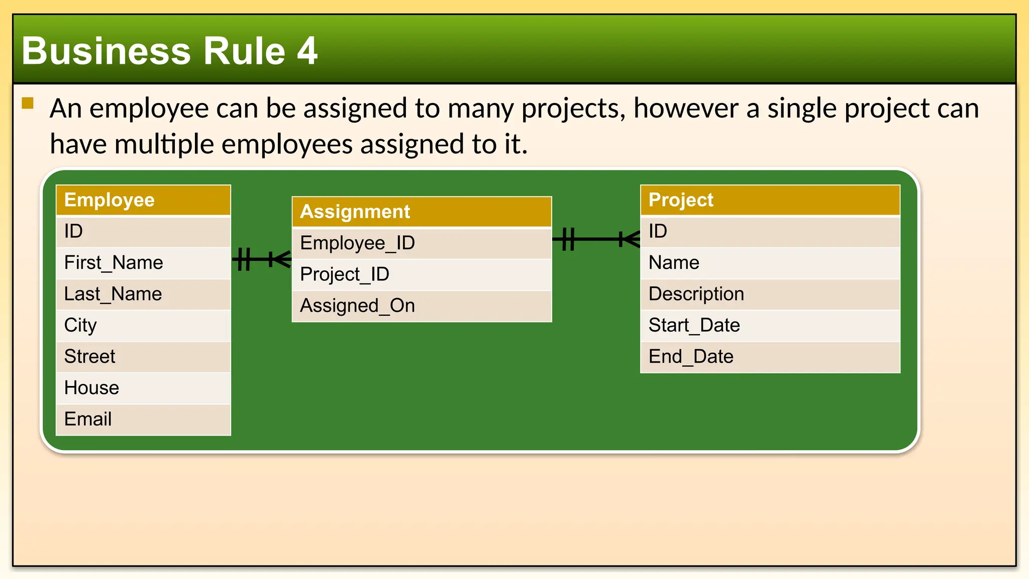
An employeecan be assigned to many projects, however a single project can
have multiple employees assigned to it.
Business Rule 4
Employee
ID
First_Name
Last_Name
City
Street
House
Email
Assignment
Employee_ID
Project_ID
Assigned_On
Project
ID
Name
Description
Start_Date
End_Date
#10 use student_db;
drop table if exists Student;
drop table if exists Course;
drop table if exists Enrolment;
CREATE TABLE Student (
id INT PRIMARY KEY AUTO_INCREMENT,
name VARCHAR(100) NOT NULL,
age INT CHECK (age > 0),
major VARCHAR(100) NOT NULL
);
CREATE TABLE Course (
id INT PRIMARY KEY AUTO_INCREMENT,
name VARCHAR(100) NOT NULL,
credit INT CHECK (credit > 0)
);
CREATE TABLE Enrolment (
Student_ID INT,
Course_ID INT,
Grade VARCHAR(2),
PRIMARY KEY (Student_ID, Course_ID),
FOREIGN KEY (Student_ID) REFERENCES Student(id) ON DELETE CASCADE,
FOREIGN KEY (Course_ID) REFERENCES Course(id) ON DELETE CASCADE
);
#18 use student_db;
drop table if exists Enrolment;
drop table if exists Student;
drop table if exists Course;
CREATE TABLE Student (
id INT PRIMARY KEY AUTO_INCREMENT,
name VARCHAR(100) NOT NULL,
age INT CHECK (age > 0),
major VARCHAR(100) NOT NULL
);
CREATE TABLE Course (
id INT PRIMARY KEY AUTO_INCREMENT,
title VARCHAR(100) NOT NULL,
credit INT CHECK (credit > 0)
);
CREATE TABLE Enrolment (
student_id INT,
course_id INT,
grade VARCHAR(2),
PRIMARY KEY (student_id, course_id),
FOREIGN KEY (student_id) REFERENCES student(id) ON DELETE CASCADE,
FOREIGN KEY (course_id) REFERENCES course(id) ON DELETE CASCADE
);
INSERT INTO Student VALUES (101, 'Alice Johnson', 20, 'Computer Science');
INSERT INTO Course VALUES (301, 'Database Systems', 3);
INSERT INTO Enrolment VALUES (101, 301, 'B+');
SELECT s.Name, c.Title, e.Grade
FROM Student s
JOIN Enrolment e ON e.student_id = s.id
JOIN Course c ON c.id = e.course_id;
#32 ACID properties in a database ensure reliable processing of transactions. The acronym stands for:
Atomicity – A transaction is all or nothing. If any part of the transaction fails, the entire transaction is rolled back, ensuring the database remains in a consistent state.
Consistency – A transaction brings the database from one valid state to another, maintaining data integrity and following all predefined constraints.
Isolation – Transactions operate independently. The intermediate state of a transaction is invisible to other transactions, preventing conflicts due to concurrent execution.
Durability – Once a transaction is committed, it remains permanent, even in case of system failures.
These properties are fundamental in ensuring data reliability and correctness in database management systems (DBMS).
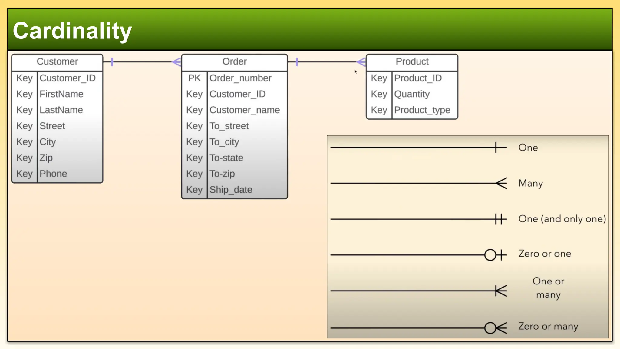
#33 Cardinality "One" (1)
This means that an entity can be associated with at most one instance of another entity, but it is not mandatory.
The association could have zero or one instance.
It is often represented as (0,1) in the min-max notation.
Example:
A Person may own one Car, but they might not own any car at all.
Representation:
Person (1,1) ⟶ (0,1) Car
Cardinality "One and Only One" (1,1)
This means that an entity must be associated with exactly one instance of another entity.
The relationship is both mandatory and exclusive.
It is often represented as (1,1) in the min-max notation.
Example:
A Passport must be issued to exactly one Person, and a Person must have exactly one Passport.
Representation:
Person (1,1) ⟶ (1,1) Passport
Key Difference
FeatureCardinality "One" (0,1)Cardinality "One and Only One" (1,1)Minimum Value01Maximum Value11Mandatory?No (can be zero)Yes (must be one)ExampleA person may have one car (but can have none).A person must have exactly one passport.