Download to read offline


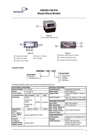
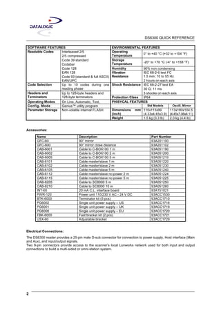
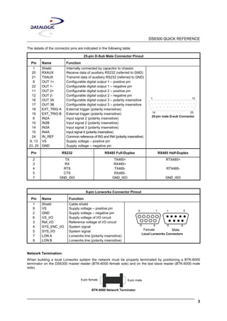
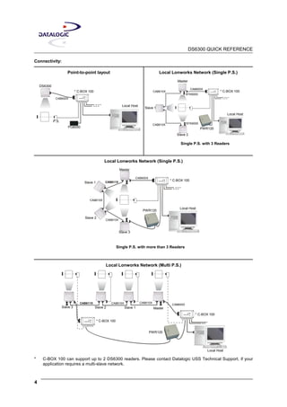
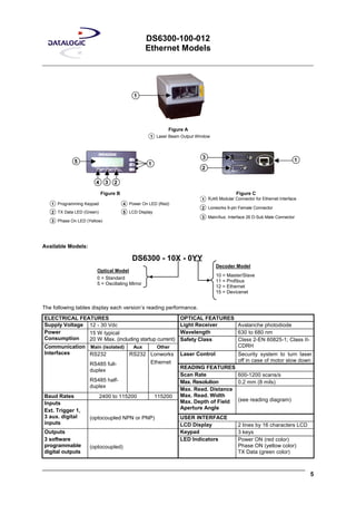
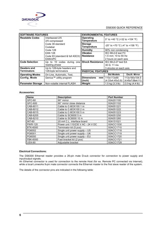
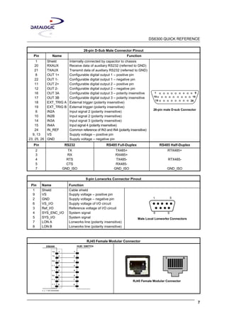

The DS6300 installation quick reference document provides detailed specifications and features for various models including master/slave, Ethernet, and oscillating mirror versions. It includes information on electrical requirements, communication interfaces, reading performance, environmental conditions, and essential connections for installation. Additionally, it lists accessories and configurations for different setups, ensuring proper usage in various applications.


![Getting Started with Apache Spark: Big Data Made Simple [Free Meetup]](https://cdn.slidesharecdn.com/ss_thumbnails/apachesparkgettingstarted-260203175547-8361bcc3-thumbnail.jpg?width=640&height=640&fit=bounds)


