Download to read offline
![MODEL: SC100
http://www.m-system.co.jp/ SC100 SPECIFICATIONS ES-6337 Rev.2 Page 1/9
Single Loop Controller Series
MULTI-FUNCTION PID CONTROLLER
(color LCD with touch-panel)
Functions & Features
• Color LCD with touch panel
• Four Operation views (digital display, bargraph, dual-loop
bargraph and short trend views)
• Enhanced screen functions for engineering (configuration,
programming and tuning views)
• Universal input x 2 points, analog input x 4 points,
discrete input x 6 points, pulse input x 5 points, high speed
pulse input x 1 point
• Current output (4-20 mA) x 2 points, voltage output (1-5
V) x 2 points, relay or photo-MOSFET relay output x 5 points
• RUN output (relay) x 1 point
• Computation cycle selectable between 50 msec. and 3
sec. (control cycle selectable between 1 and 64 times of the
computation cycle)
• Two PID function blocks
• Advanced computation and sequence control functions
• Auto-tuning function
• Parameter input and changing with touch panel
• Function parameter setting, list printing and data
downloading/uploading available with Loop Configuration
Builder Software (model: SFEW3E)
• Display parameter setting, saving and transfer with PC
Configurator Software (model: SCCFG)
• Selectable housing depth for ease of using existing wires
in replacement: 250 mm, 300 mm, 400 mm and 600 mm
Typical Applications
• Replacement of conventional controllers
• Panel operation for small-scale instrumentation
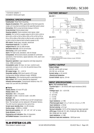
144
(5.67)
72
(2.83)
mm (inch)
*Selectable with option code
*
MODEL: SC100–[1]0–[2][3]
ORDERING INFORMATION
• Code number: SC100-[1]0-[2][3]
Specify a code from below for each [1] through [3].
(e.g. SC100-10-M2/300/E/1)
[1] DISCRETE OUTPUT
1: Relay contact
2: Photo MOSFET relay
MODBUS
0:None
[2] POWER INPUT
AC Power
M2: 100 – 240 V AC (Operational voltage range 85 – 264 V, 50/60 Hz)
DC Power
R: 24 V DC
(Operational voltage range 24 V ±10 %, ripple 10 %p-p max.)
[3] OPTIONS (multiple selections)
Housing Depth
blank: 250 mm
/300: 300 mm
/400: 400 mm
/600: 600 mm
Language
blank: Japanese
/E: English
(Language (Japanese or English) can be chosen by front
panel setting.)
Configurator Interface
blank: Infrared
/1: Stereo jack
RELATED PRODUCTS
• PC Configurator cable (model: COP-US)
• Loop configuration builder software (model: SFEW3E Ver.
1.40 or later)
• Infrared communication adaptor (model: COP-IRDA)
• PC configurator software (model: SCCFG Ver.1.50 or later)
Builder software and configurator software are
downloadable at M-System’s web site.
ACCESSORIES
• Precision resistor module (model: REM4): 2
• Cold junction sensor: 2
• Mounting brackets: 2](https://image.slidesharecdn.com/essc100-130618011002-phpapp02/85/SINGLE-LOOP-CONTROLLER-SERIES-1-320.jpg)
![MODEL: SC100
http://www.m-system.co.jp/ SC100 SPECIFICATIONS ES-6337 Rev.2 Page 3/9
Burnout indication: 115 % of the measuring range (upscale)
Sensing current: ≤ 1 mA
∙Potentiometer input: Total resistance 100 Ω to 10 kΩ
Minimum span: 50 % of total resistance
Excitation: ≤ 0.6 V DC
■ Ai1, Ai2, Ai3, Ai4
∙Voltage input: 1 – 5 V DC
Input resistance: ≥ 1 MΩ
■ Pi1, Pi2, Pi3, Pi4, Pi5: Dry contact
(Di1 through Di5 are assigned to the same terminals
respectively.)
Maximum frequency: 20 Hz
Minimum pulse width: 25 msec.
Input resistance: Approx. 2 kΩ
Common: Negative common per 5 points
Sensing: Approx. 12 V DC
ON voltage/resistance: ≤ 2.25 V, ≤ 1.5 kΩ
OFF voltage/resistance: ≥ 11.25 V ≥ 15 kΩ
■ Pi6: Dry contact
(Di6 is assigned to the same terminal.)
Maximum frequency: 10 kHz
Minimum pulse width: 0.05 msec.
Input resistance: Approx. 1 kΩ
Common: Negative common
Sensing: Approx. 12 V DC
ON voltage/resistance: ≤ 2 V, ≤ 1.5 kΩ
OFF voltage/resistance: ≥ 11 V, ≥ 15 kΩ
Excitation: 12 V DC ±10%, 15 mA
Current limiting circuit: Approx. 30 mA
■ Di1, Di2, Di3, Di4, Di5: Dry contact
(Pi1 through Pi5 are assigned to the same terminals
respectively.)
Input resistance: Approx. 2 kΩ
Common: Negative common per 5 points
Sensing: Approx. 12 V DC
ON voltage/resistance: ≤ 2.25 V, ≤ 1.5 kΩ
OFF voltage/resistance: ≥ 11.25 V ≥ 15 kΩ
■ Di6: Dry contact
(Pi6 is assigned to the same terminal.)
Input resistance: Approx. 1 kΩ
Common: Negative common
Sensing: Approx. 12 V DC
ON voltage/resistance: ≤ 2 V, ≤ 1.5 kΩ
OFF voltage/resistance: ≥ 11 V, ≥ 15 kΩ
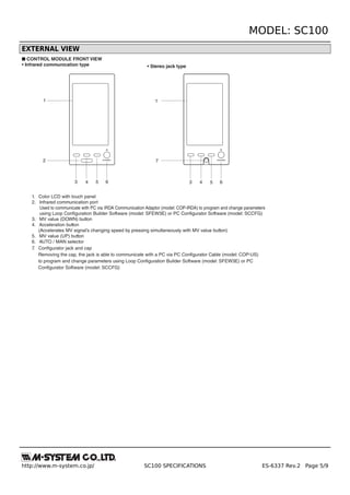
[Table 1 (Thermocouple input)]
T/C
USABLE
RANGE (°C)
CONFORMANCE
RANGE (°C)
K (CA) -272 to +1472 -150 to +1370
E (CRC) -272 to +1100 -170 to +1000
J (IC) -260 to +1300 -180 to +1200
T (CC) -272 to +500 -170 to +400
B (RH) 24 to 1920 400 to 1760
R -100 to +1860 200 to 1760
S -100 to +1860 0 to 1760
C (WRe 5-26) -52 to +2416 0 to 2315
N -272 to +1400 -130 to +1300
U -252 to +700 -200 to +600
L -252 to +1000 -200 to +900
P (Platinel II) -52 to +1496 0 to 1395
(PR) -52 to +1860 0 to 1760
Overrange input (out of the usable range) is handled as burnout.
[Table 2 (RTD input)]
RTD
USABLE
RANGE (°C)
CONFORMANCE
RANGE (°C)
Pt 100 (JIS ’97, IEC) -240 to +900 -200 to +850
Pt 100 (JIS ’89) -240 to +900 -200 to +660
JPt 100 (JIS ’89) -236 to +560 -200 to +510
Pt 50Ω (JIS ’81) -236 to +700 -200 to +649
Ni 100 -100 to +252 -80 to +250
Overrange input (out of the usable range) is handled as burnout.
OUTPUT SPECIFICATIONS
■ Mv1, Mv2
∙Current output: 4 – 20 mA DC
Load resistance: ≤ 600 Ω
■ Ao1, Ao2
∙Voltage output: 1 – 5 V DC
Load resistance: ≥ 10 kΩ
■ Discrete Output
∙Do1, Do2, Do3, Do4, Do5, RUN contact (Do6): Relay
contact
Rated load: 250 V AC @1 A (cos ø = 1)
30 V DC @1 A (resistive load)
Maximum switching voltage: 250 V AC or 30 V DC
Maximum switching power: 250 VA or 60 W
Minimum load: 5 V DC @10 mA
Mechanical life: 2 × 10
7
cycles
∙Do1, Do2, Do3, Do4, Do5: Photo MOSFET relay
Rating: 200 V AC/DC @0.5 A (resistive load)
ON resistance: 2.1 Ω
Maximum frequency: 4 Hz @24 V, 10 mA
ON delay time: ≤ 5.0 msec.
OFF delay time: ≤ 3.0 msec.](https://image.slidesharecdn.com/essc100-130618011002-phpapp02/85/SINGLE-LOOP-CONTROLLER-SERIES-3-320.jpg)
![MODEL: SC100
http://www.m-system.co.jp/ SC100 SPECIFICATIONS ES-6337 Rev.2 Page 7/9
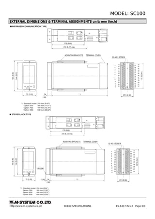
MOUNTING REQUIREMENTS unit: mm
138
68 [68+72×(n - 1)]
+1
0
+0.7
0
Panel thickness 2.3 – 20
138
+1
0
+1
0
■ PANEL CUTOUT unit: mm
• Single mounting • Clustered mounting
n = number of units
■ Caution
• IP55 is ensured for the front panel of the unit mounted independently to according to a panel. Test the sealing at the
mounting surface once the device is installed.
• Set the unit on a vertical surface with its operation buttons at the lower side. Mounting in other directions may cause heat
built up inside the unit and shorten its life span or degrade its performance.
• Ensure that there is sufficient space for ventilation inside a panel. Do not install above the devices that generate high heat
such as heaters, transformers or resistors. Observe at the minimum of 30 mm (1.2”) in all directions for maintenance purpose
(e.g. wiring, removing or installing).](https://image.slidesharecdn.com/essc100-130618011002-phpapp02/85/SINGLE-LOOP-CONTROLLER-SERIES-7-320.jpg)

This document provides specifications for the SC100 single loop controller from M-System. The SC100 features a color LCD touch panel, universal inputs and outputs, PID control functions, alarm functions, and communication capabilities. It has two PID function blocks and supports advanced computation, sequence control, and auto-tuning functions. The controller can be programmed and configured via the touch panel or with external software. Specifications include details on inputs and outputs, display, control functions, installation requirements, and performance metrics.


