Download to read offline


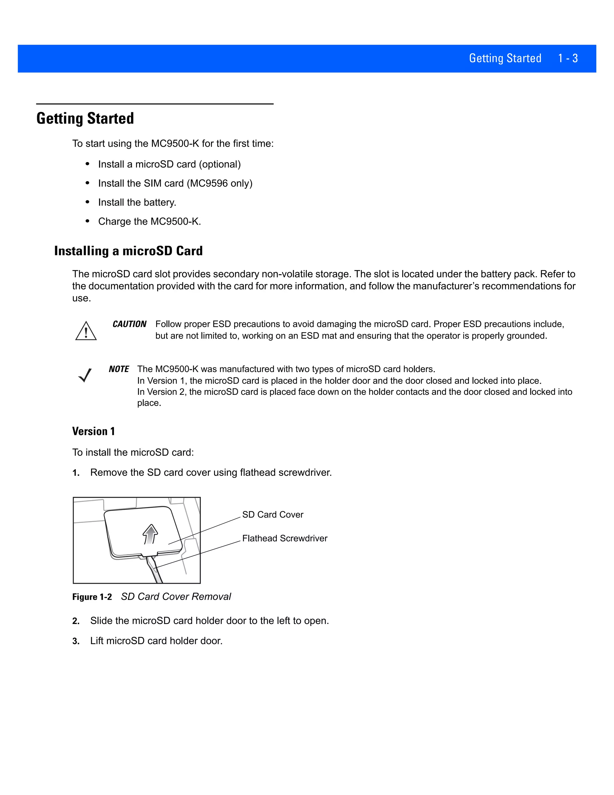
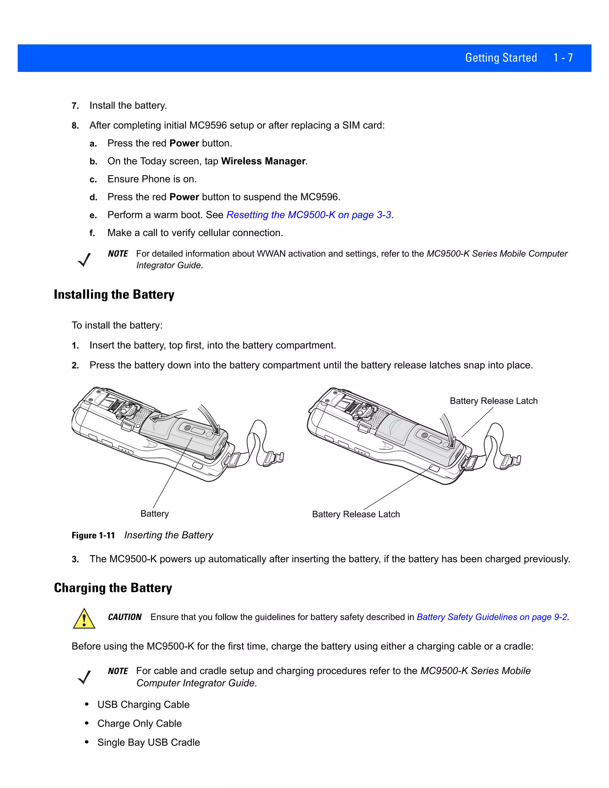


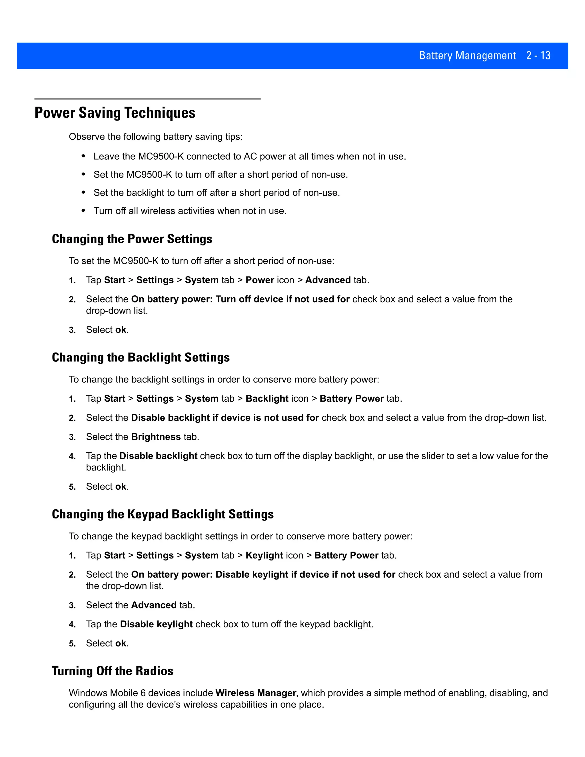

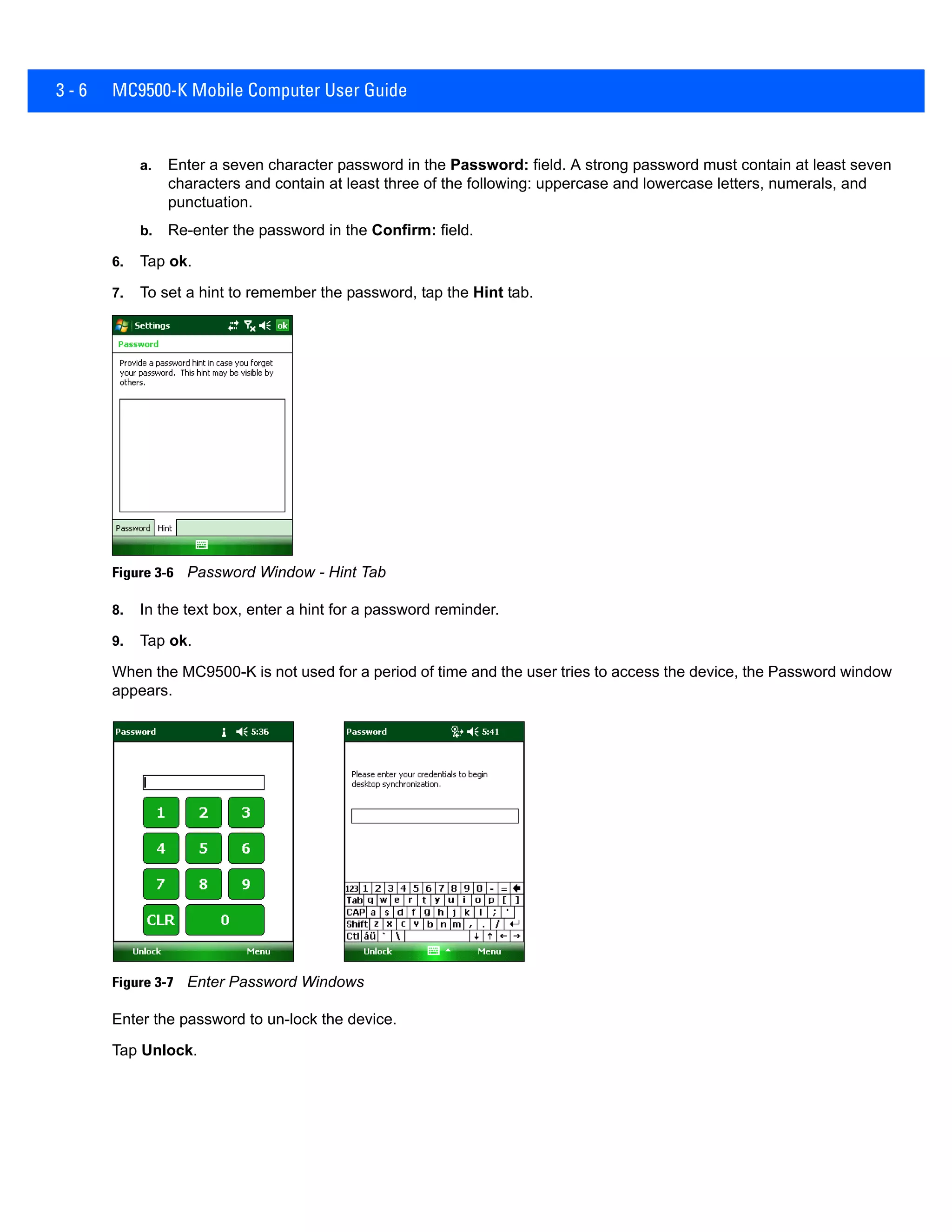
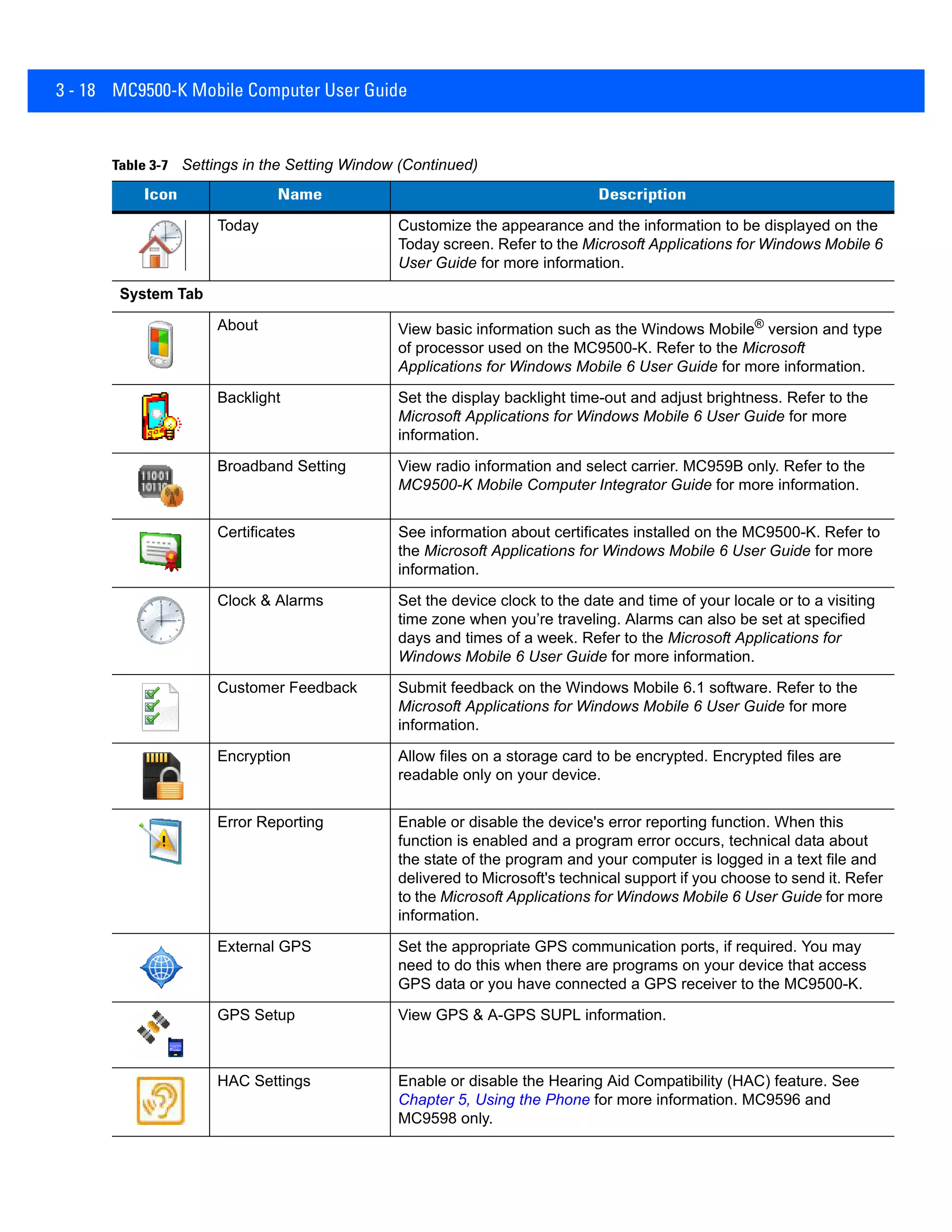
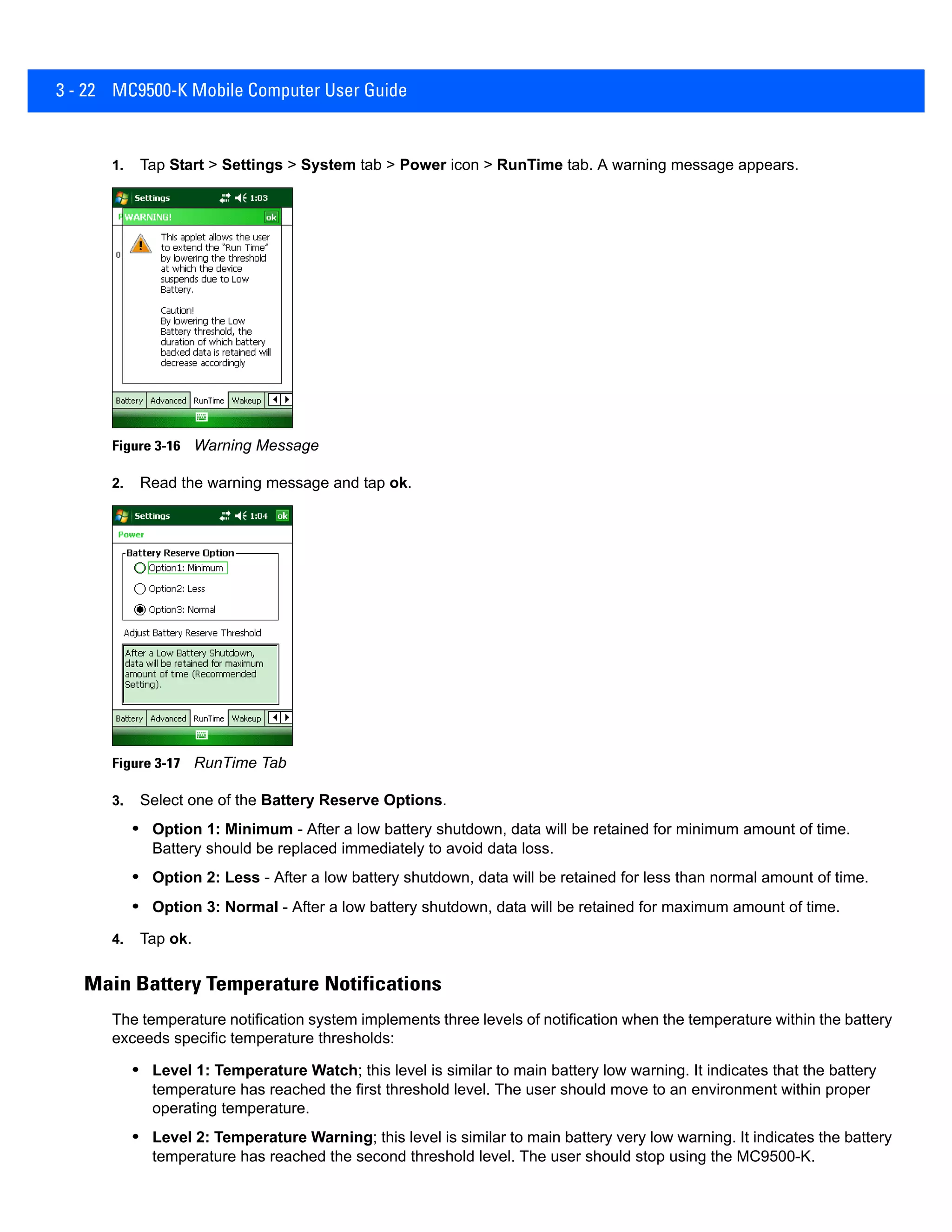
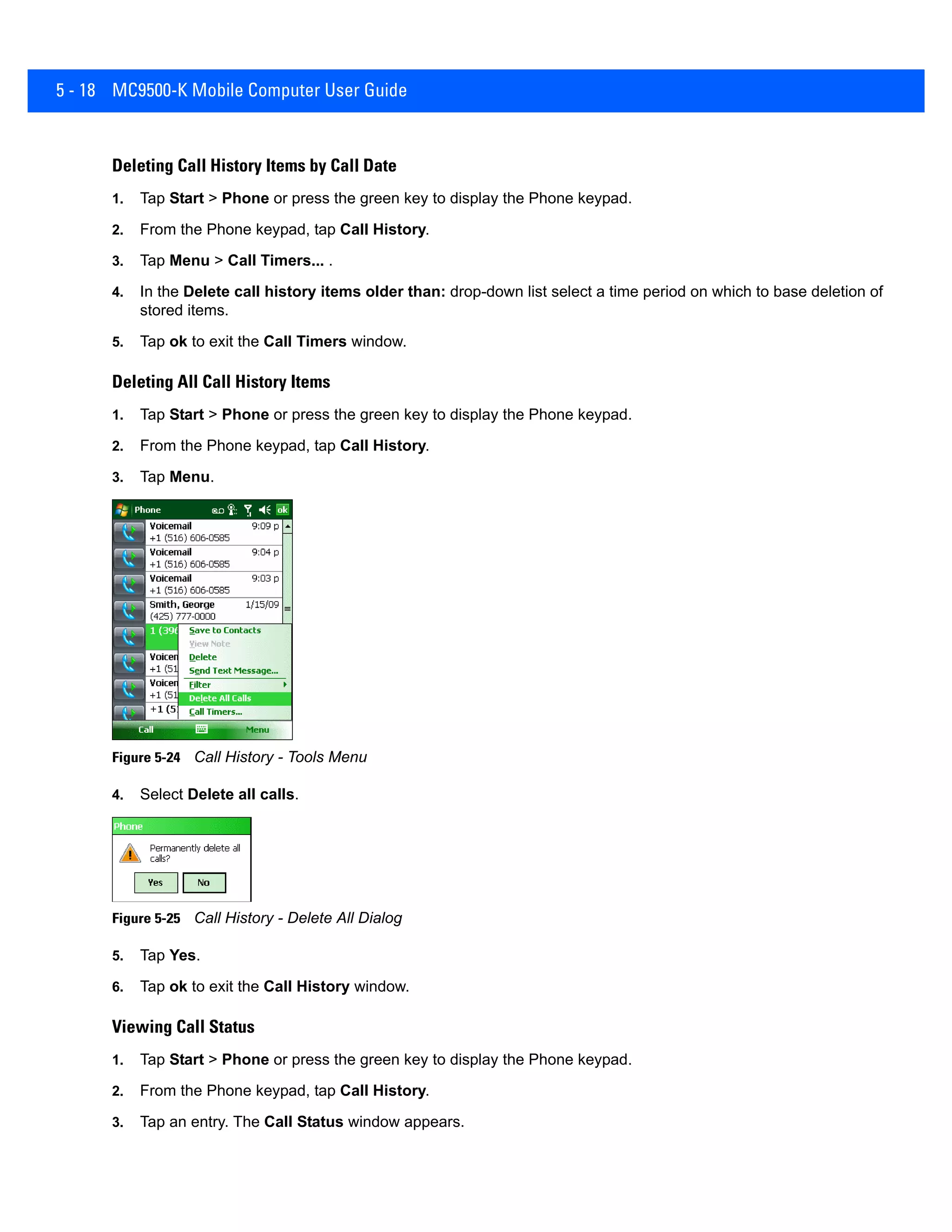
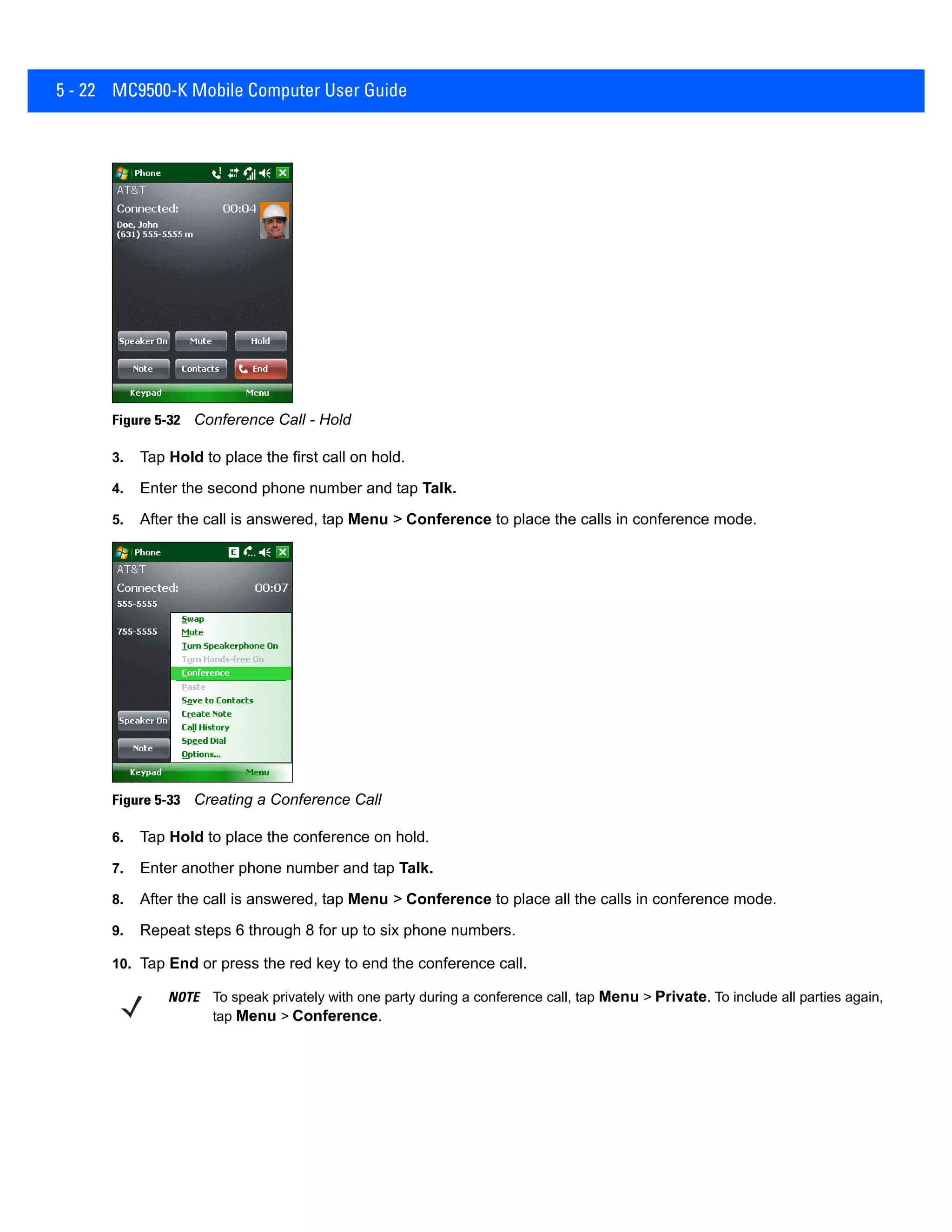
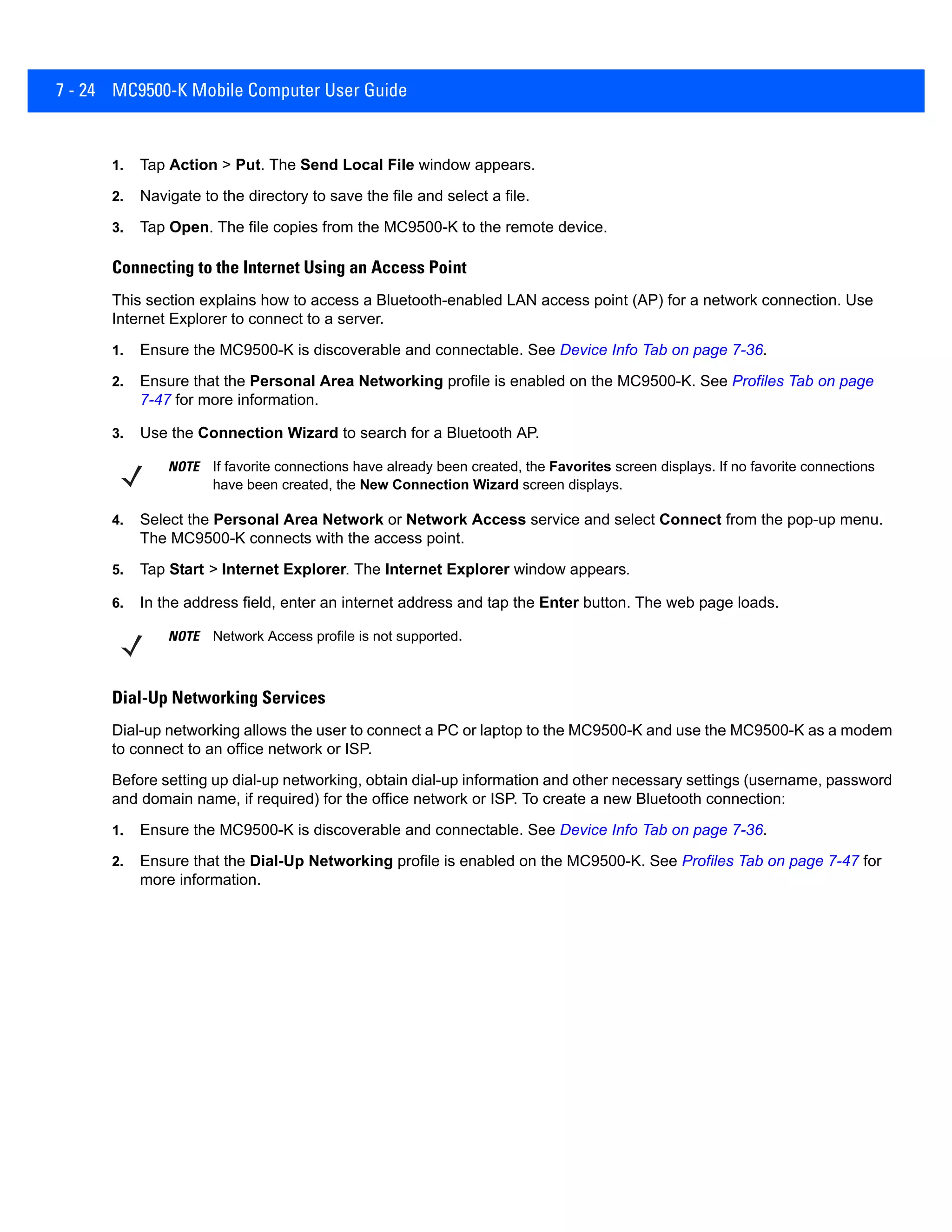
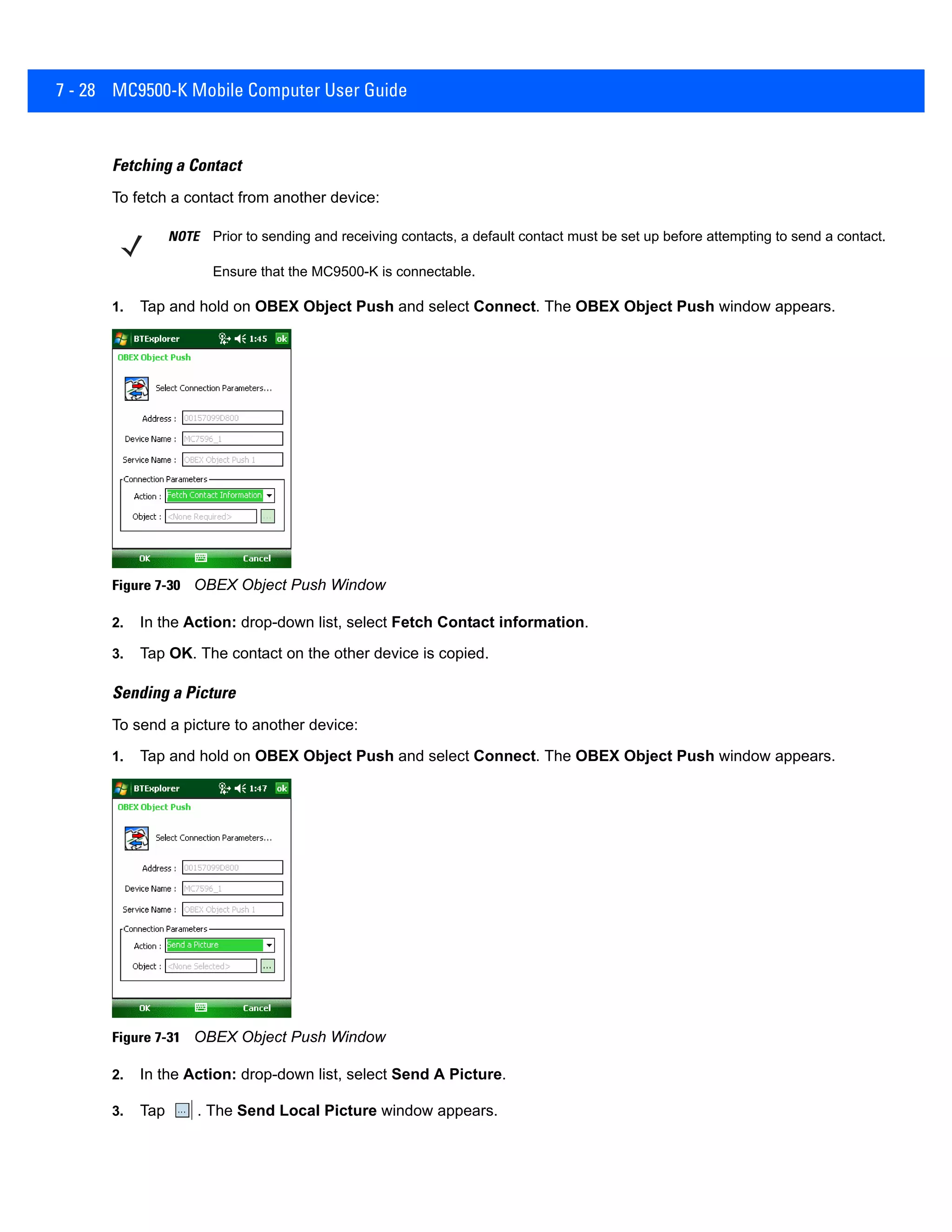
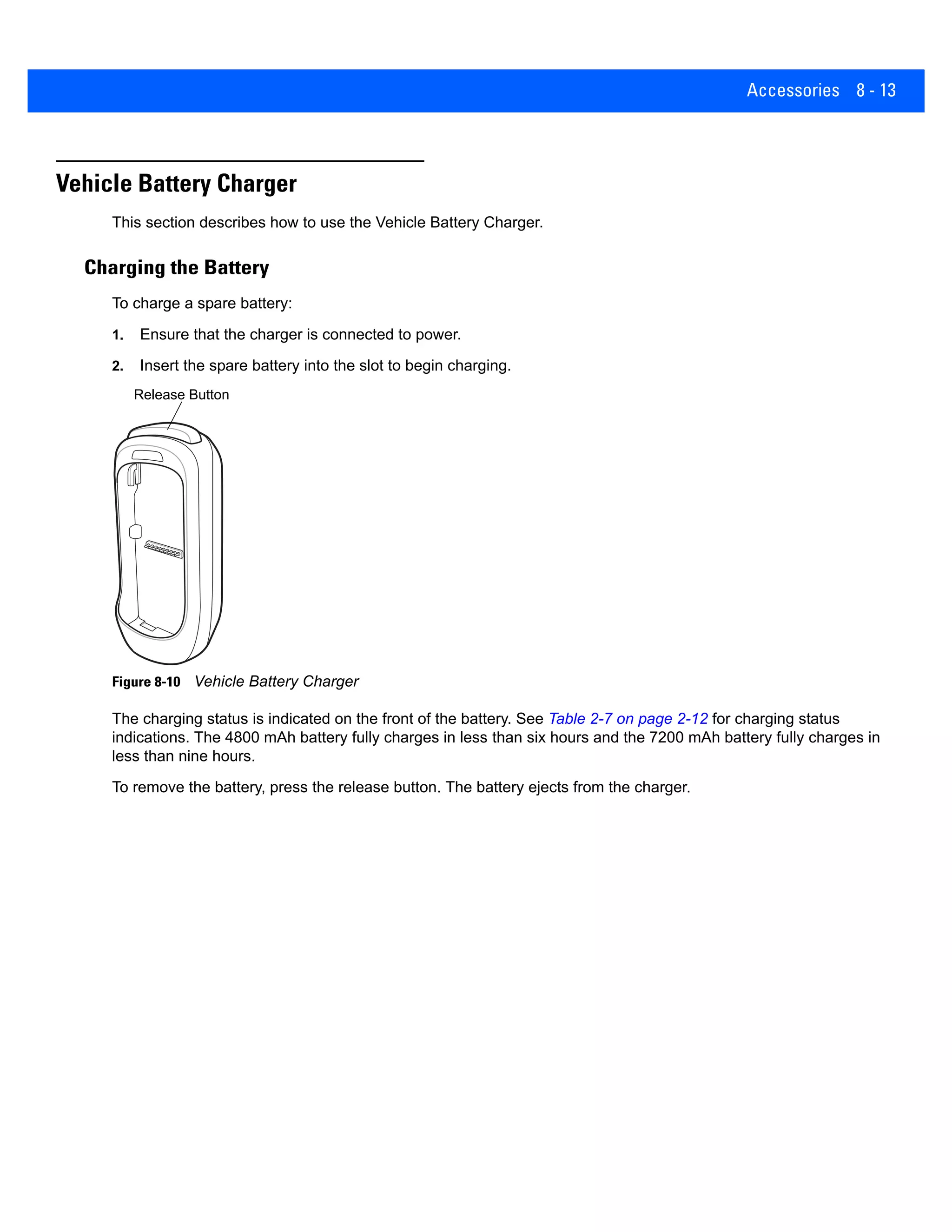
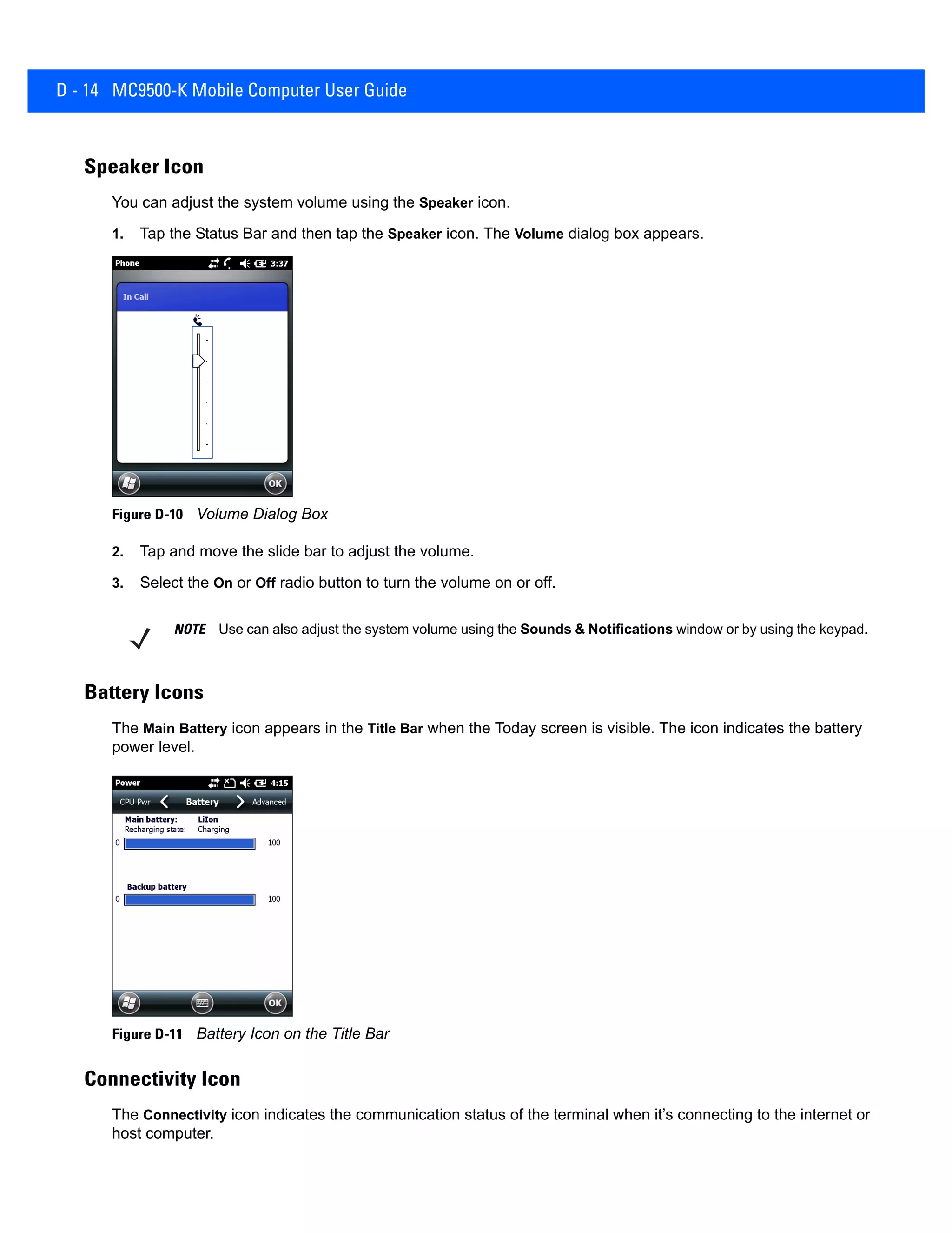
![3 - 24 MC9500-K Mobile Computer User Guide
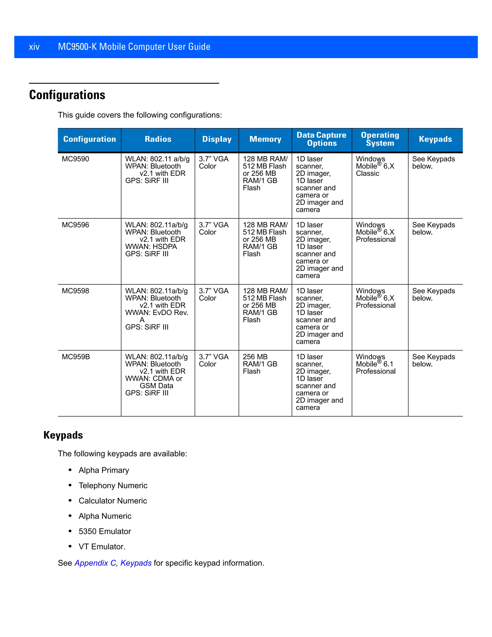
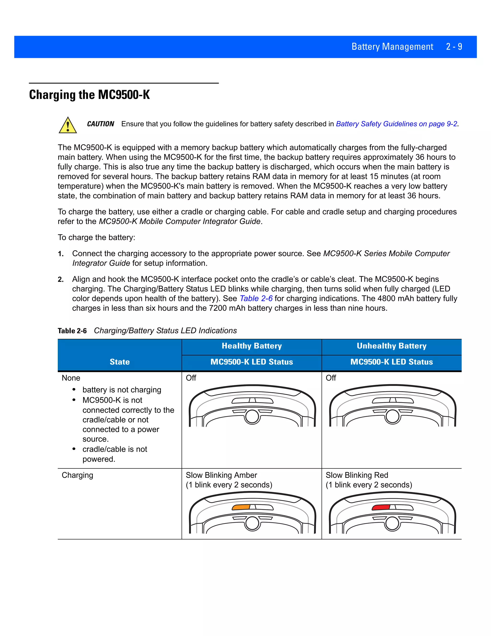
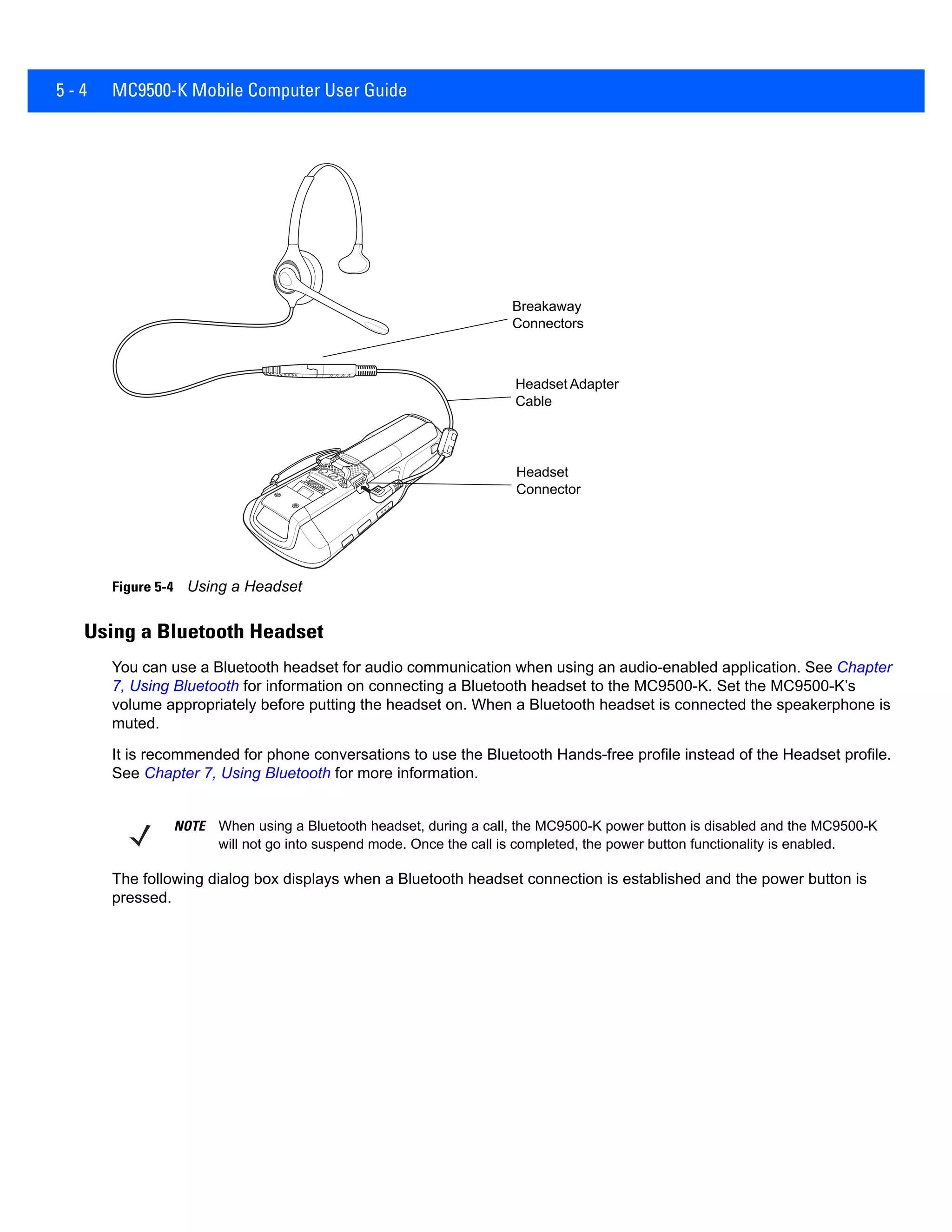
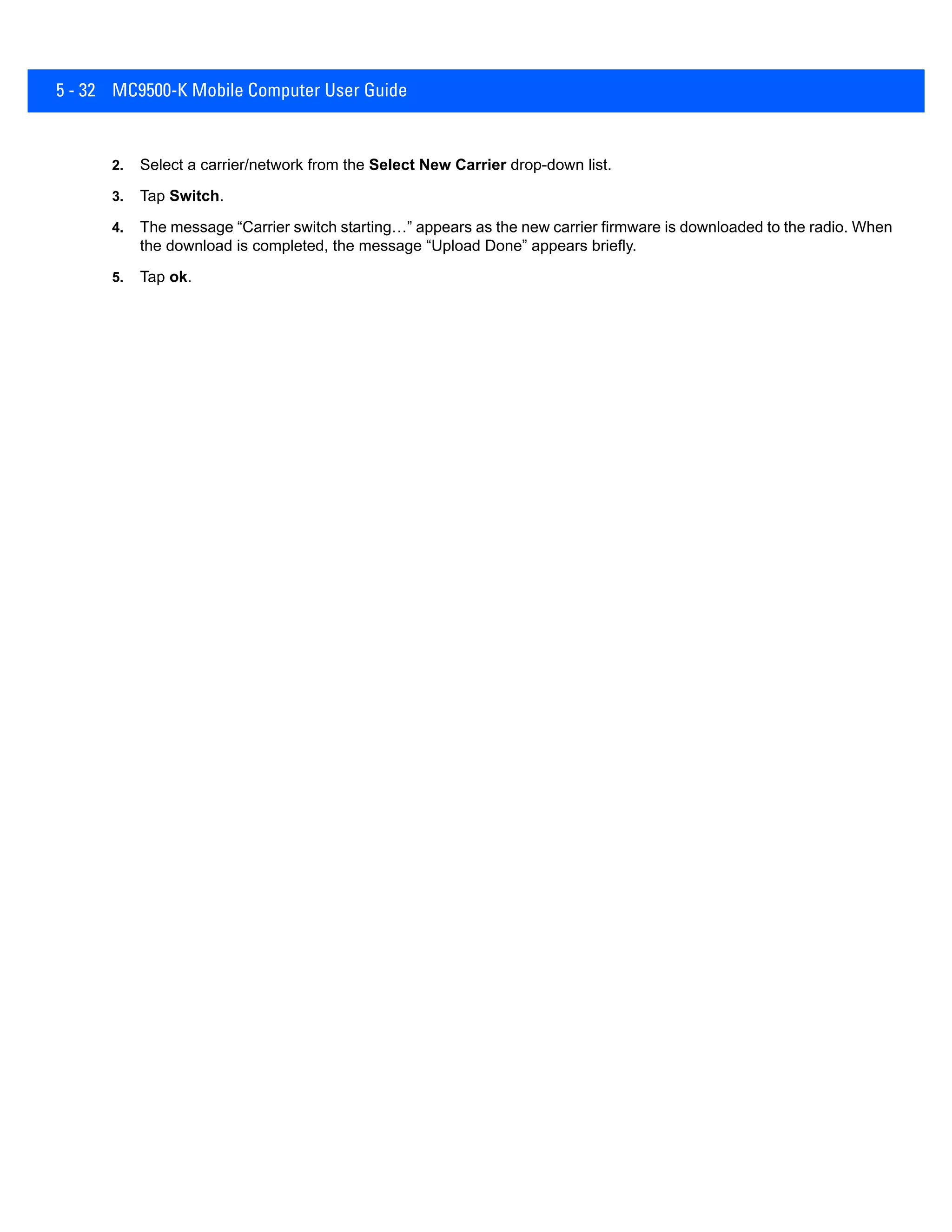
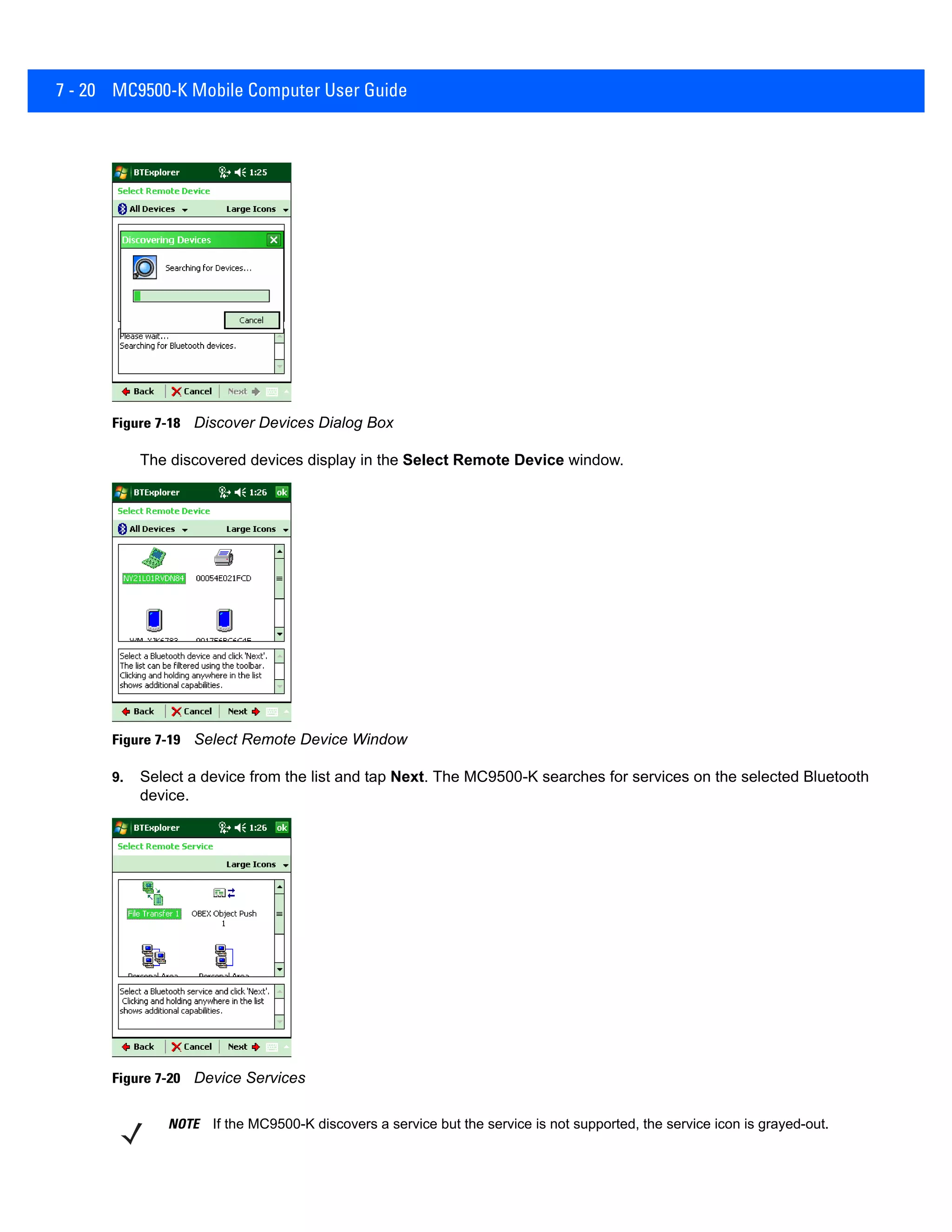
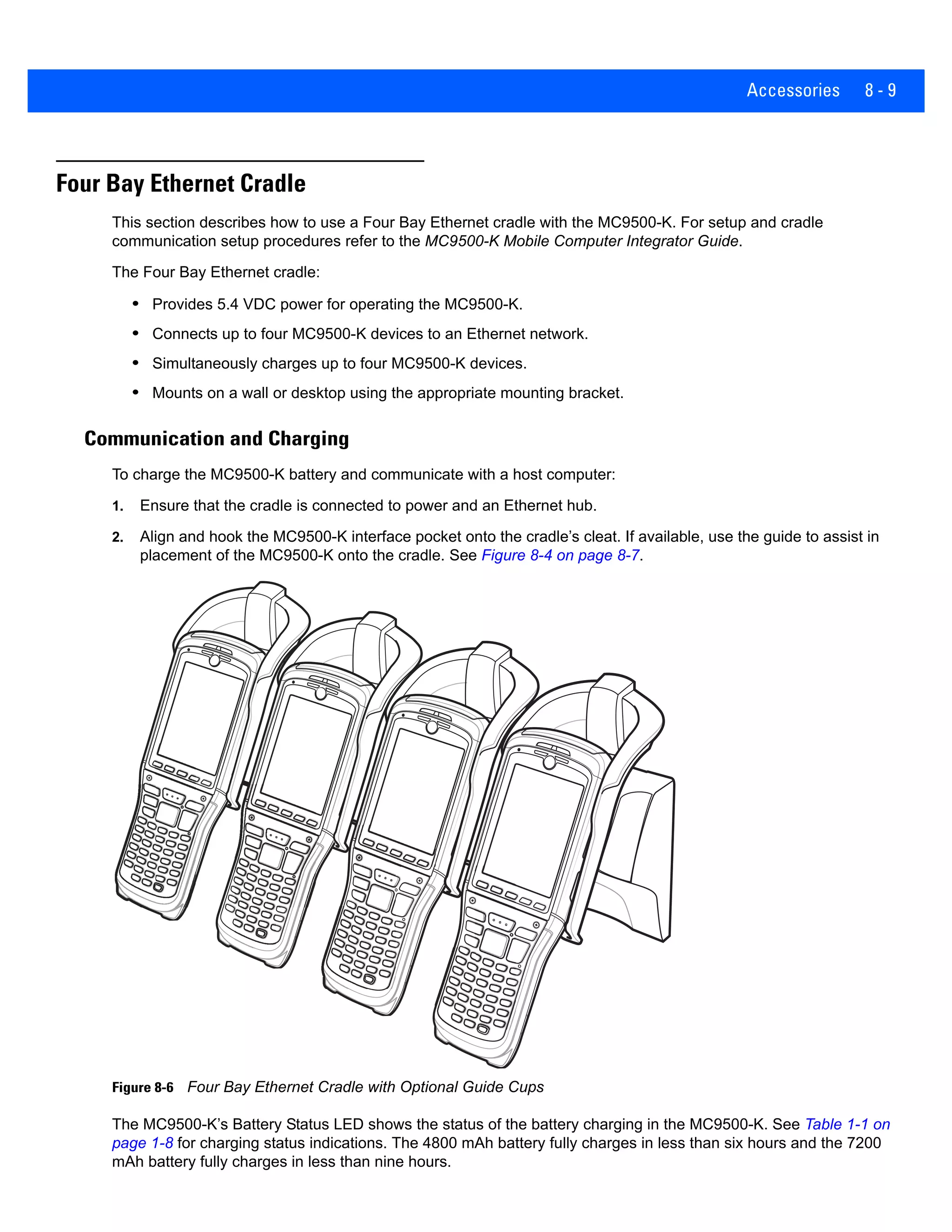
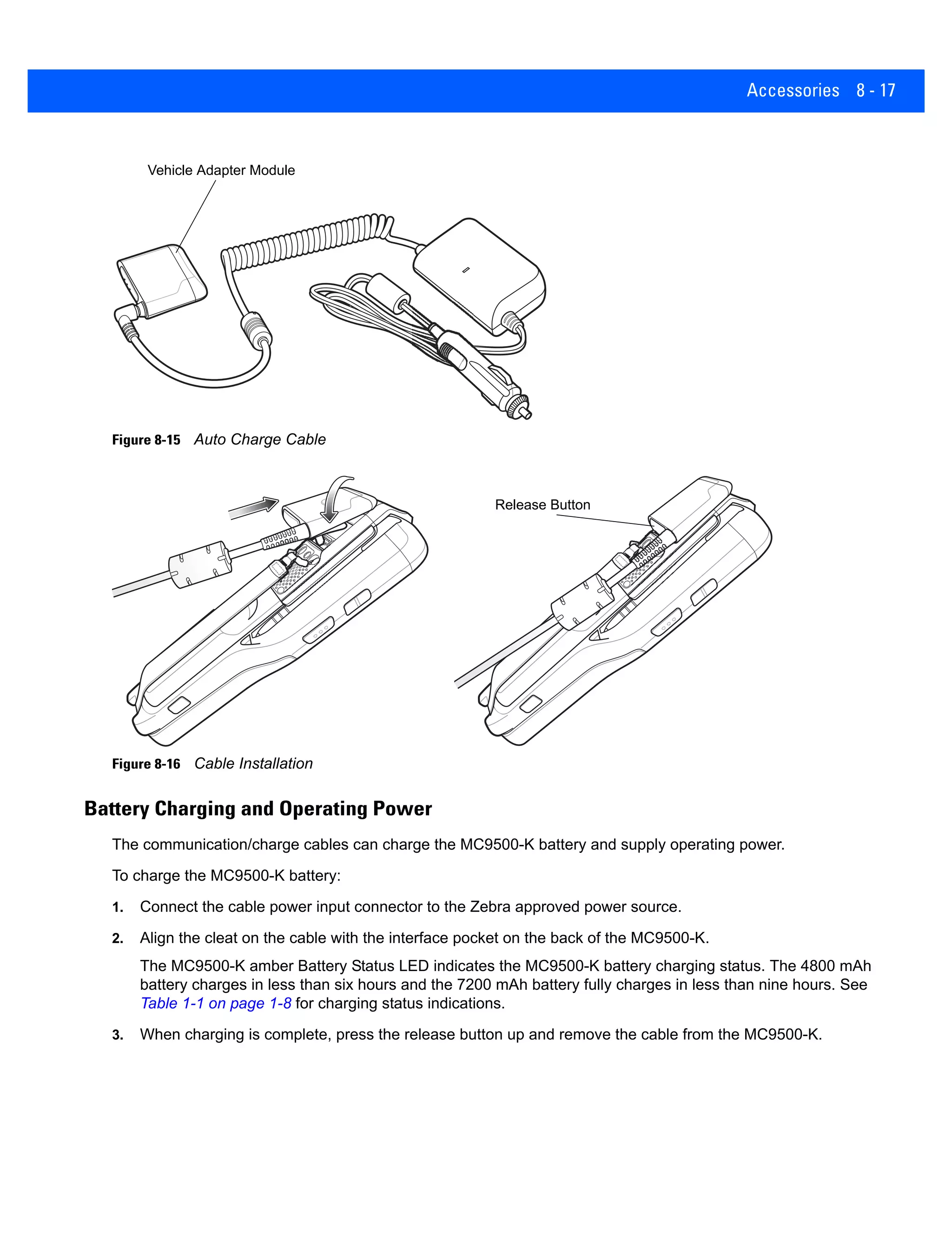
Infrared Connection
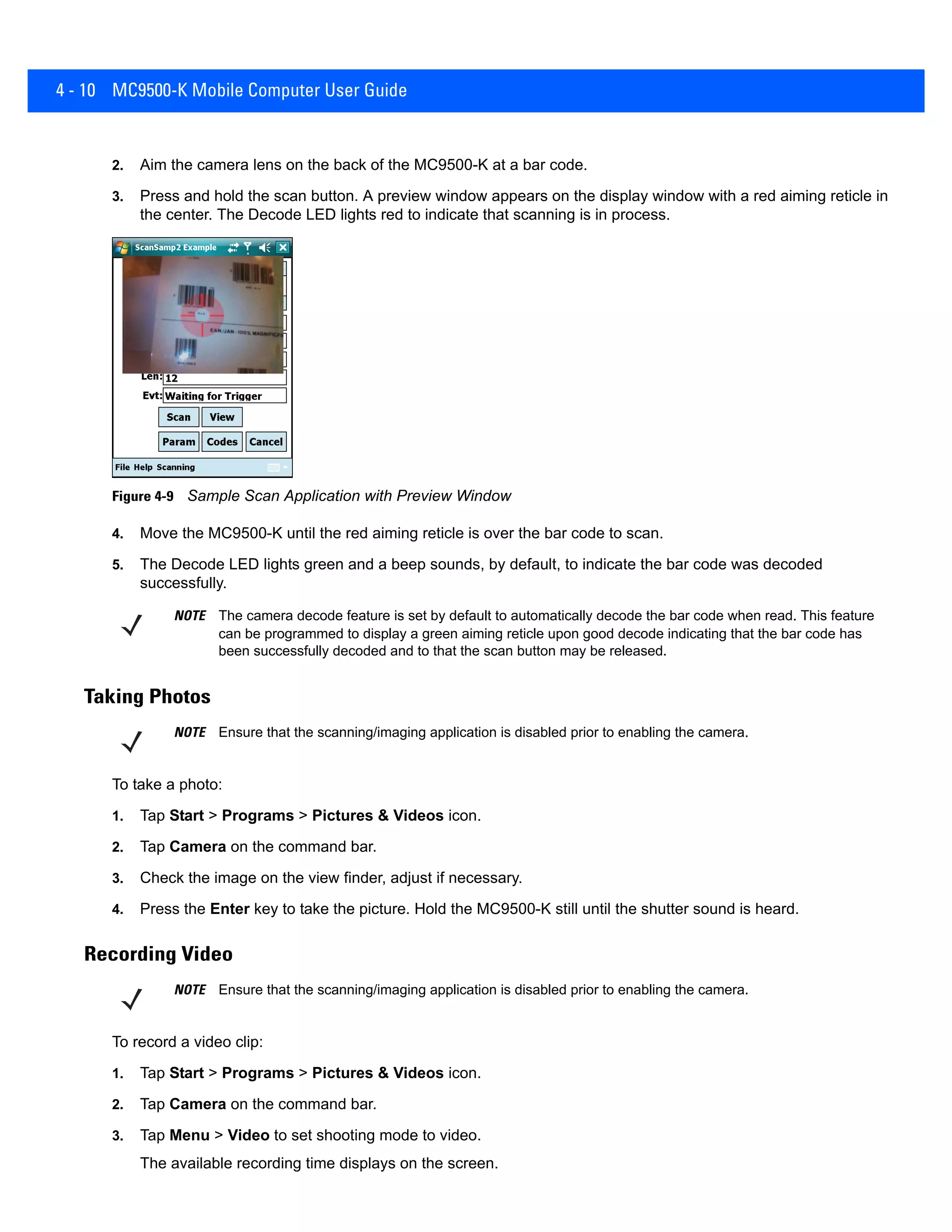
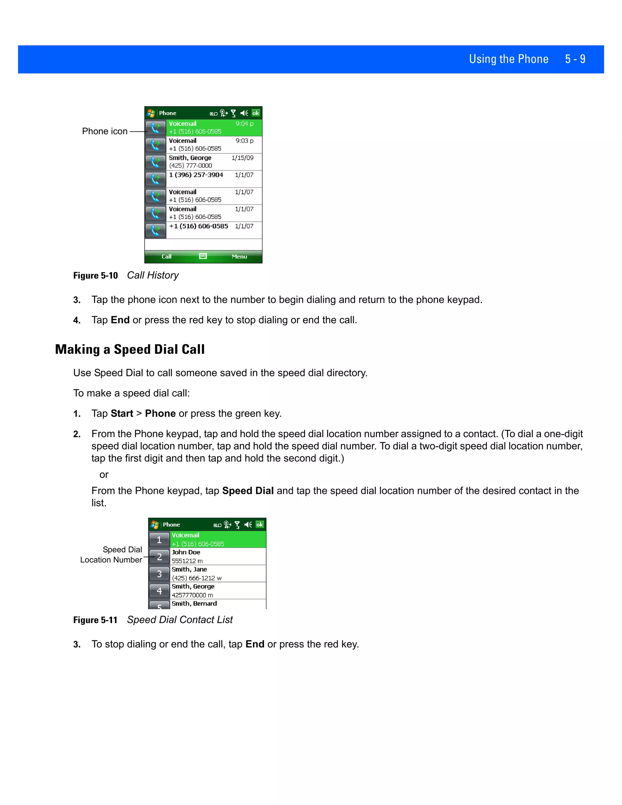
Using infrared, you can enable short-range file exchange between your MC9500-K and another IrDA device.
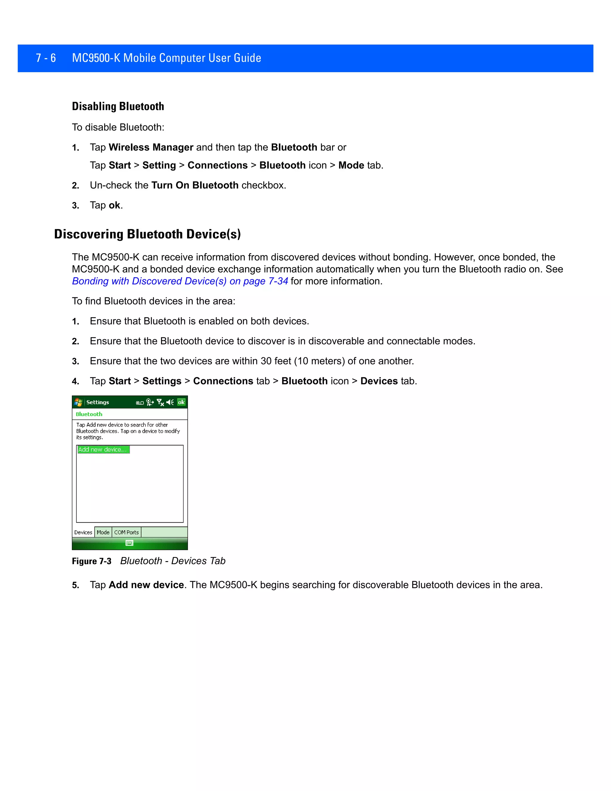
Exchanging Files using IR Connection
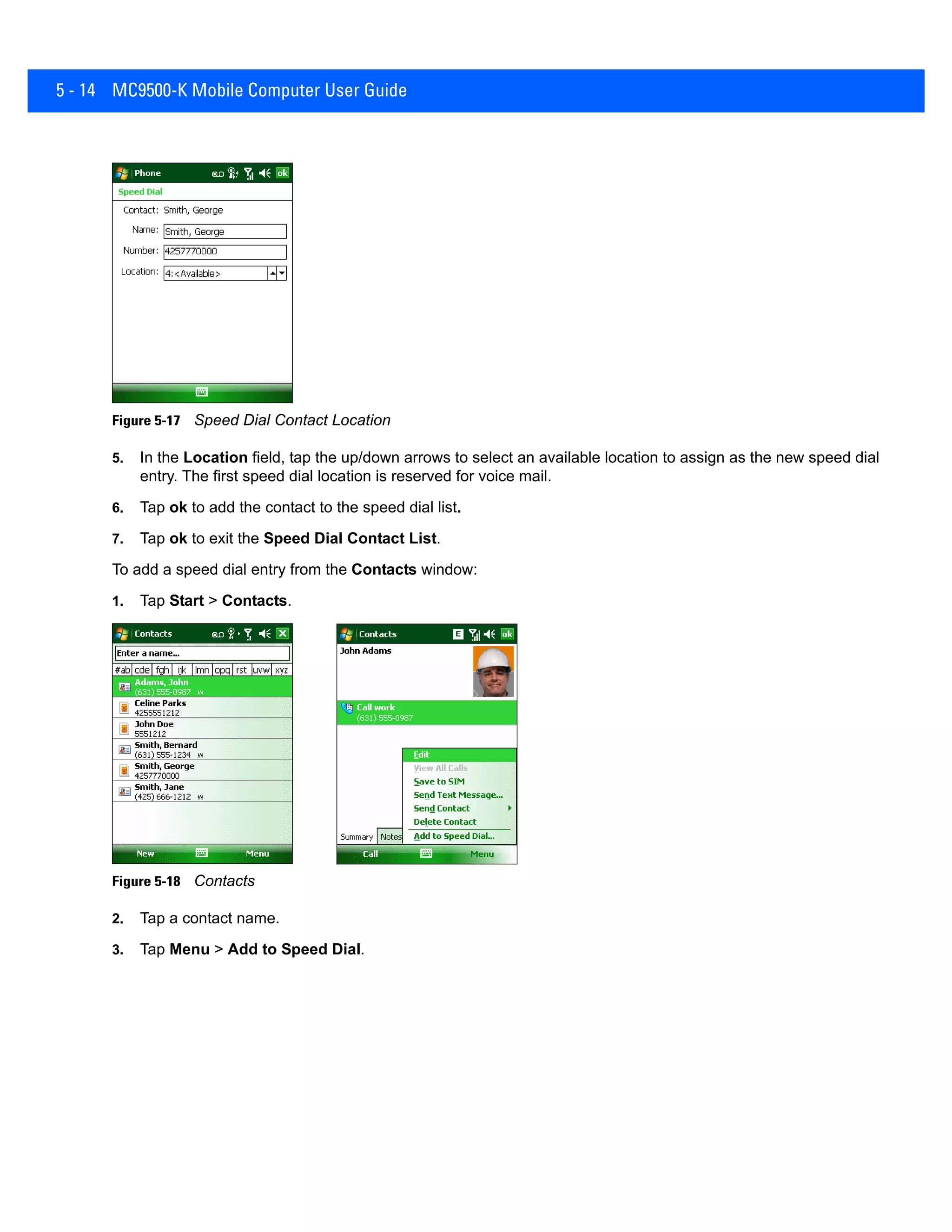
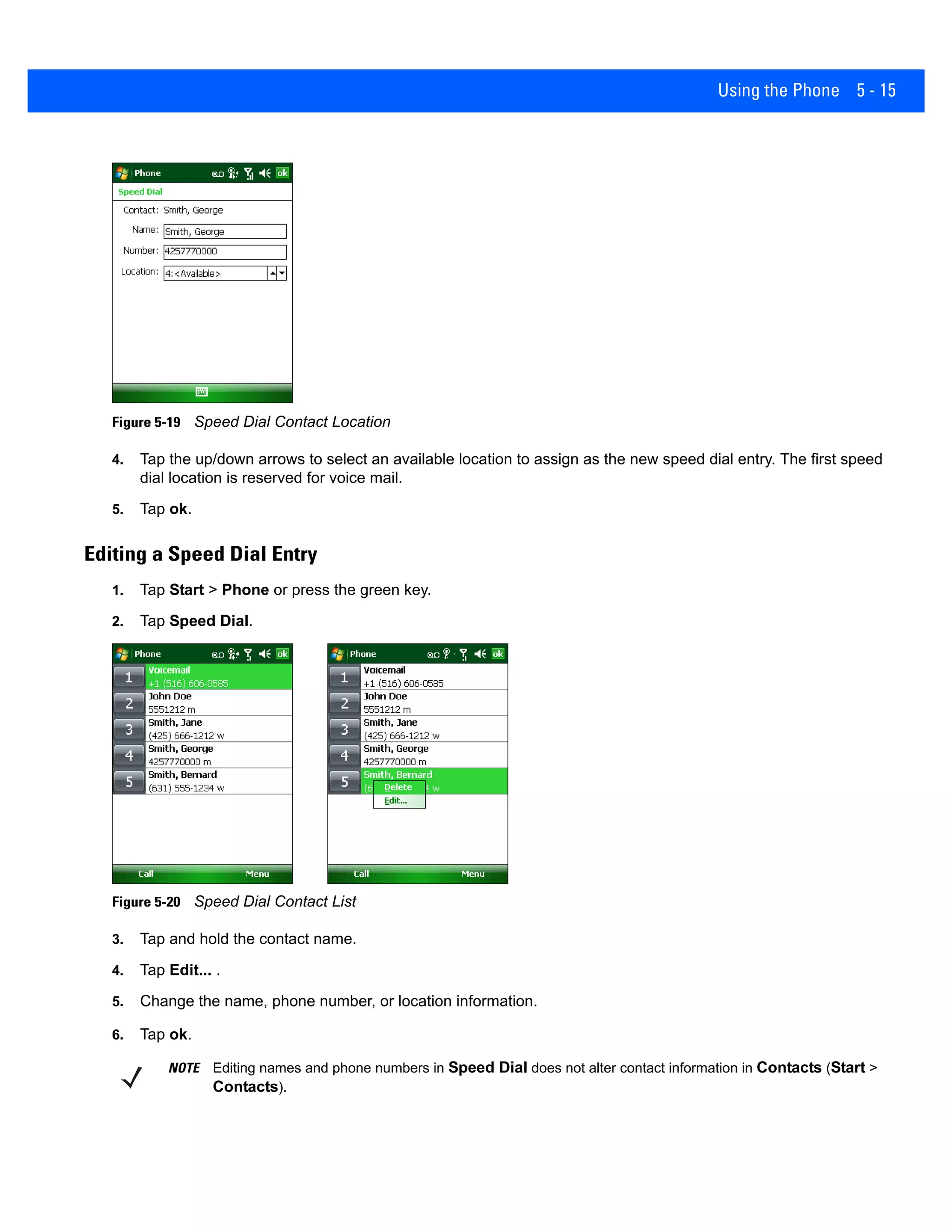
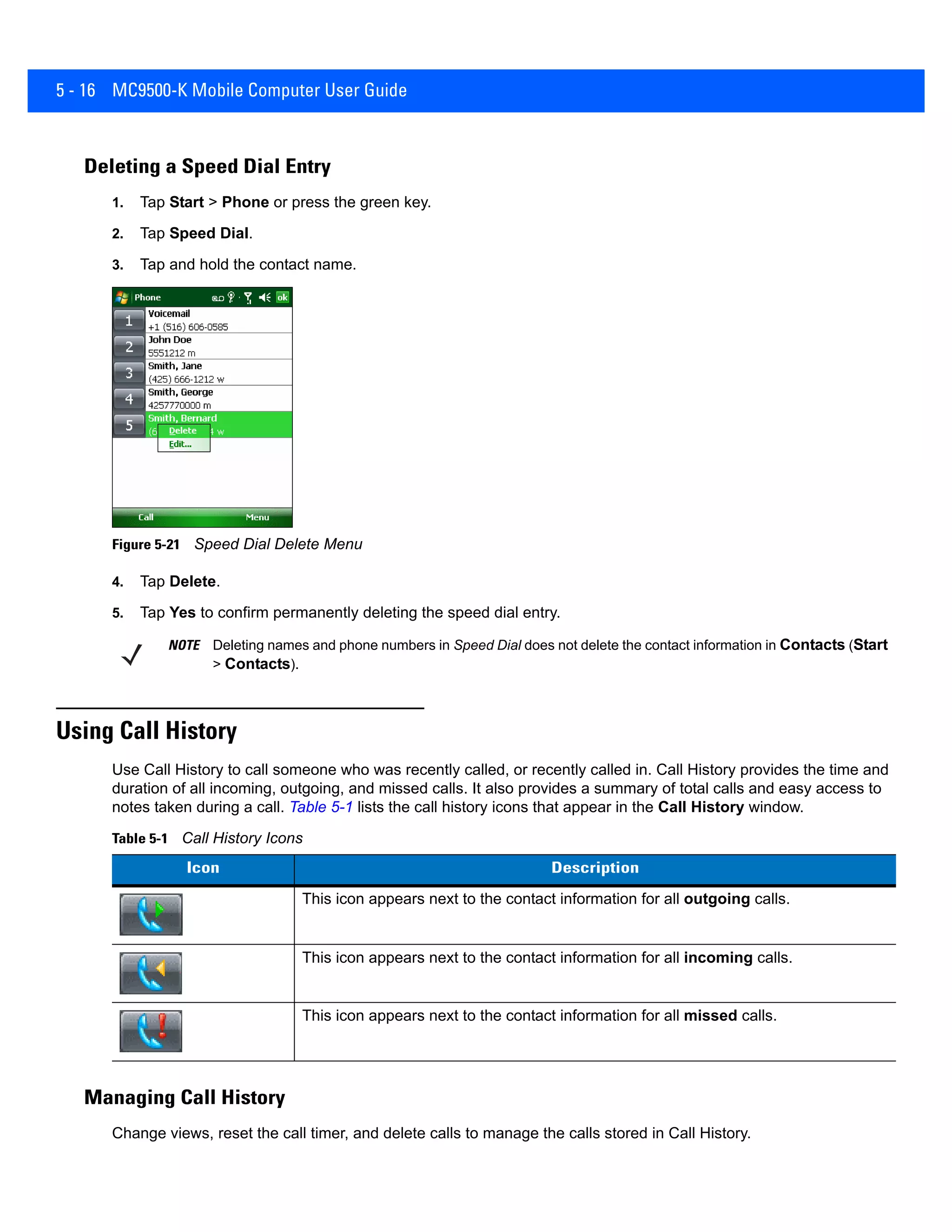
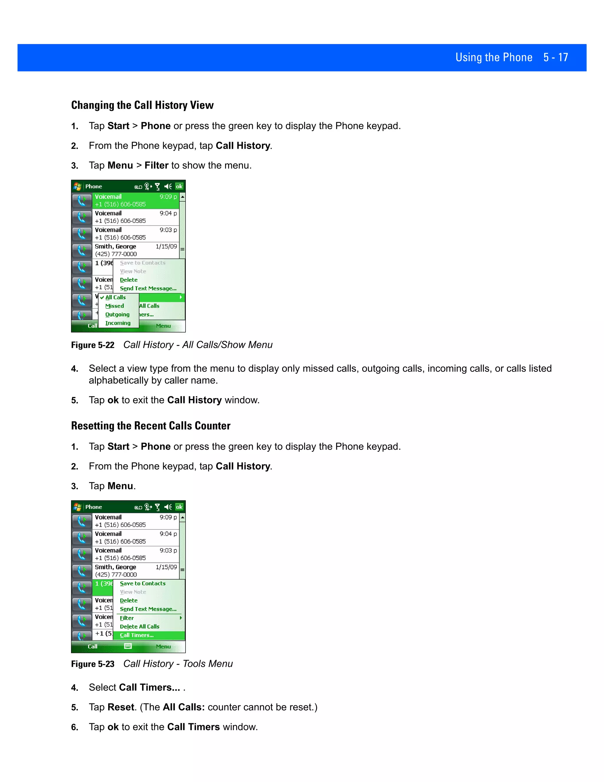
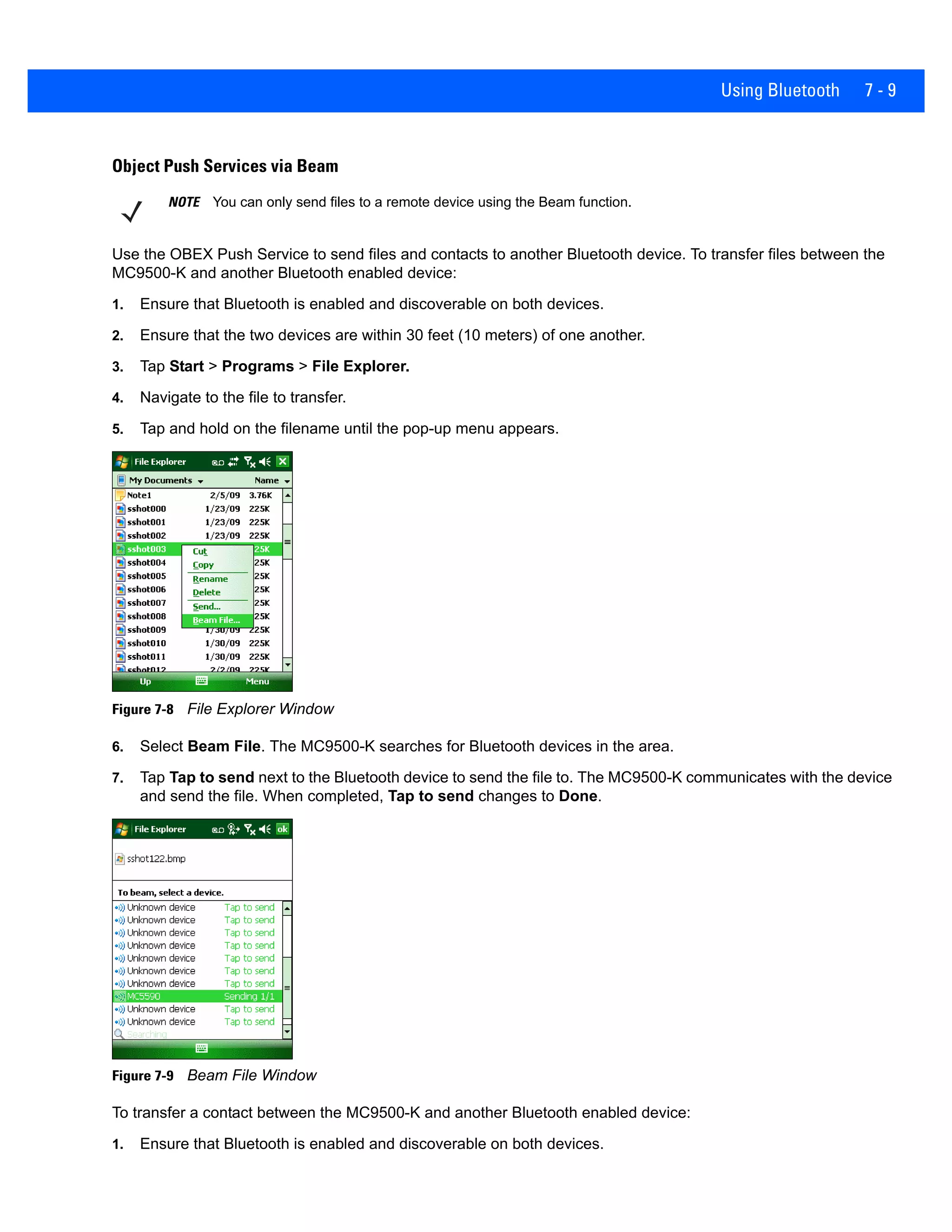
Ensure that the IrDA function on both the MC9500-K and the other device are enabled.
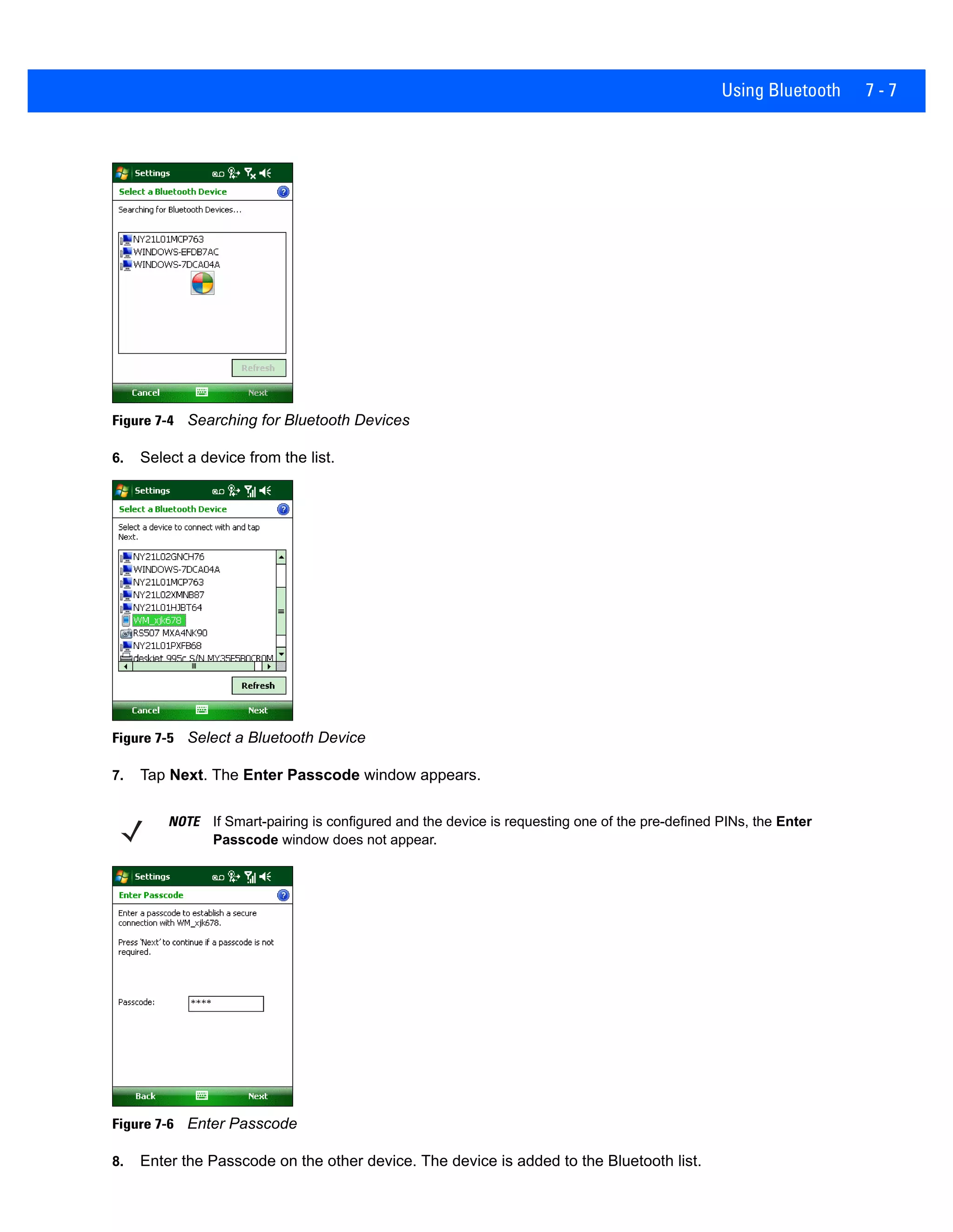
To send files via IrDA connection:
1. Switch to the program where you created the item you want to send and locate the item in the list.
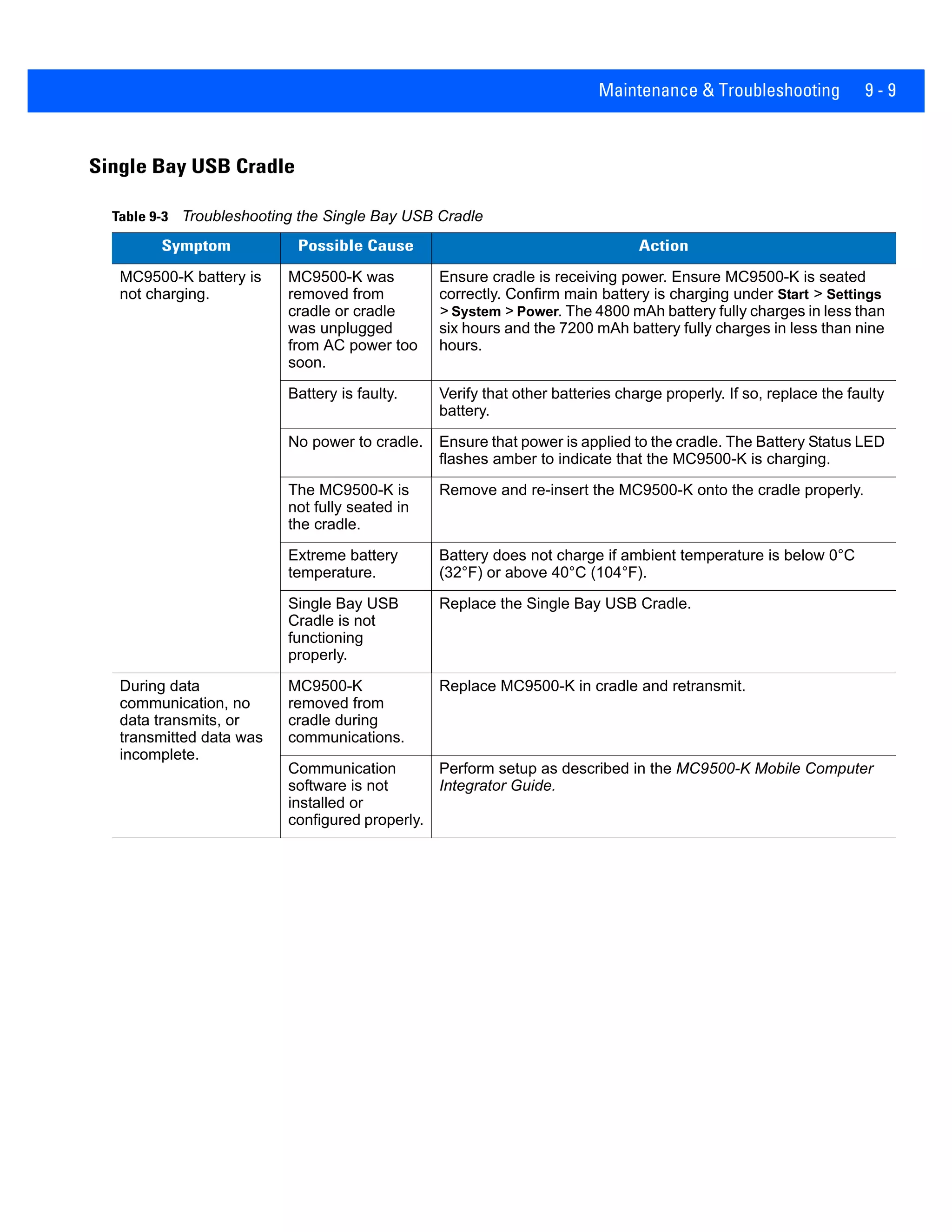
2. Align the IrDA port of the MC9500-K with that of the IrDA device so that they are unobstructed and within a
close range.
Figure 3-20 Align MC9500-K with IrDA Device
3. Tap and hold the item, then tap Beam [type of item] on the pop-up menu.
4. Tap the device that you want to send the file to.
NOTE Do not cover or block the IrDA window.](https://image.slidesharecdn.com/zebramc9500-k2dindustrialpdausermanualhionit-190726042310/75/PDA-Zebra-MC9500-K-2D-PDA-PDA-74-2048.jpg)


![Using the Phone 5 - 11
• If a caller isn't in your contact list, create a contact during the call or from Call History by tapping Menu >
Save to Contacts.
• To terminate a call when a second call comes in and answer the waiting call, tap End on the Phone keypad to
disconnect the active call, then tap Answer or press the Send key to answer the waiting call.
• To hold the current call and answer a waiting call, tap Answer or press the Send key to place the current call
on hold and answer the incoming call.
• To put a call on hold to call another number or answer an incoming call, tap Hold. To move from one call to
another, tap Swap.
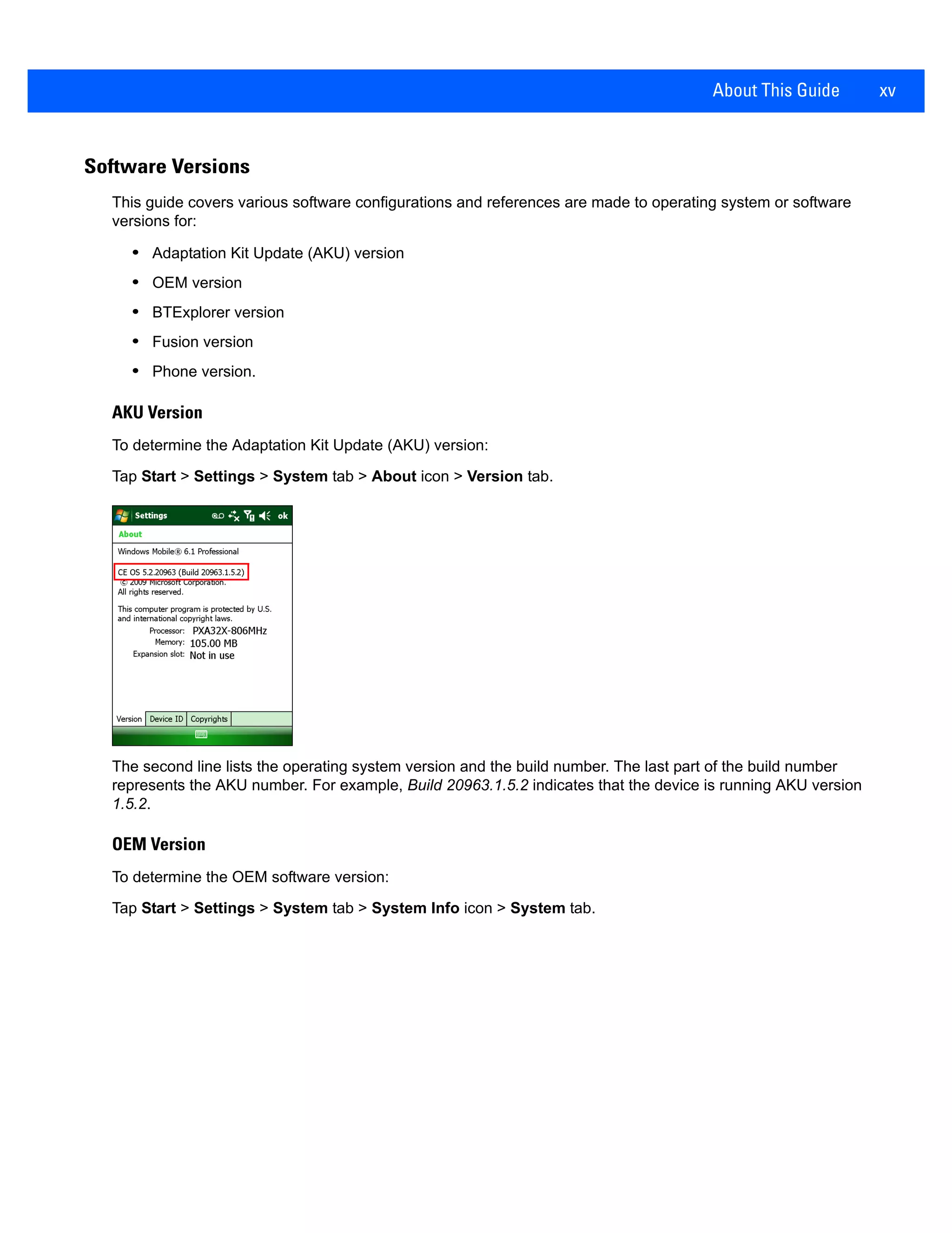
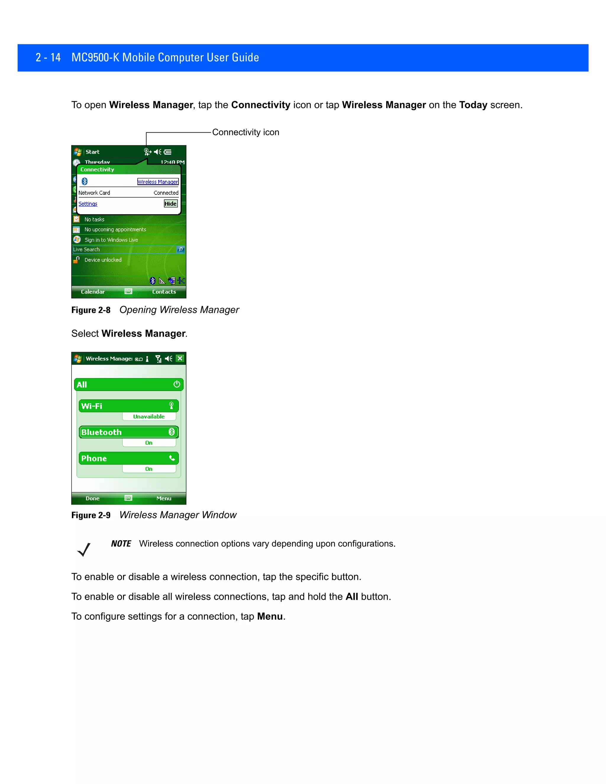
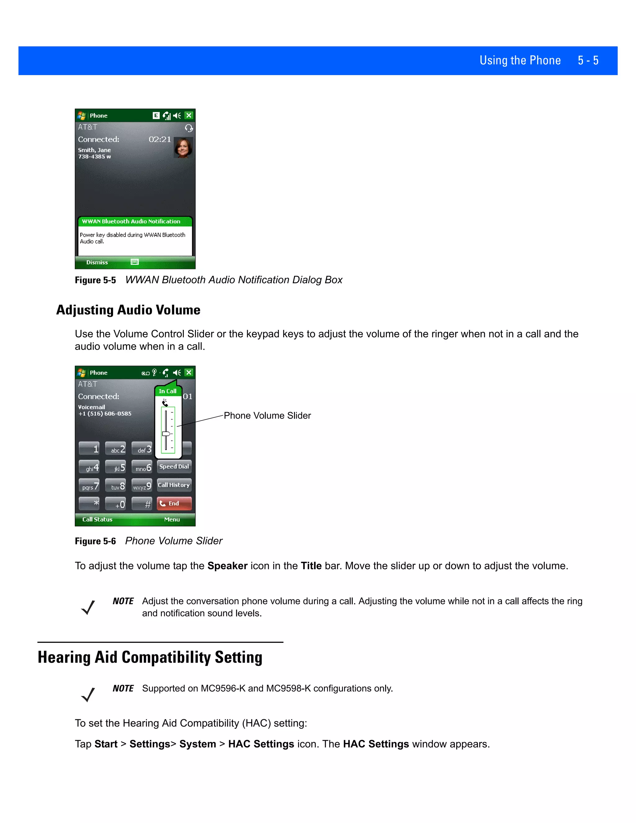
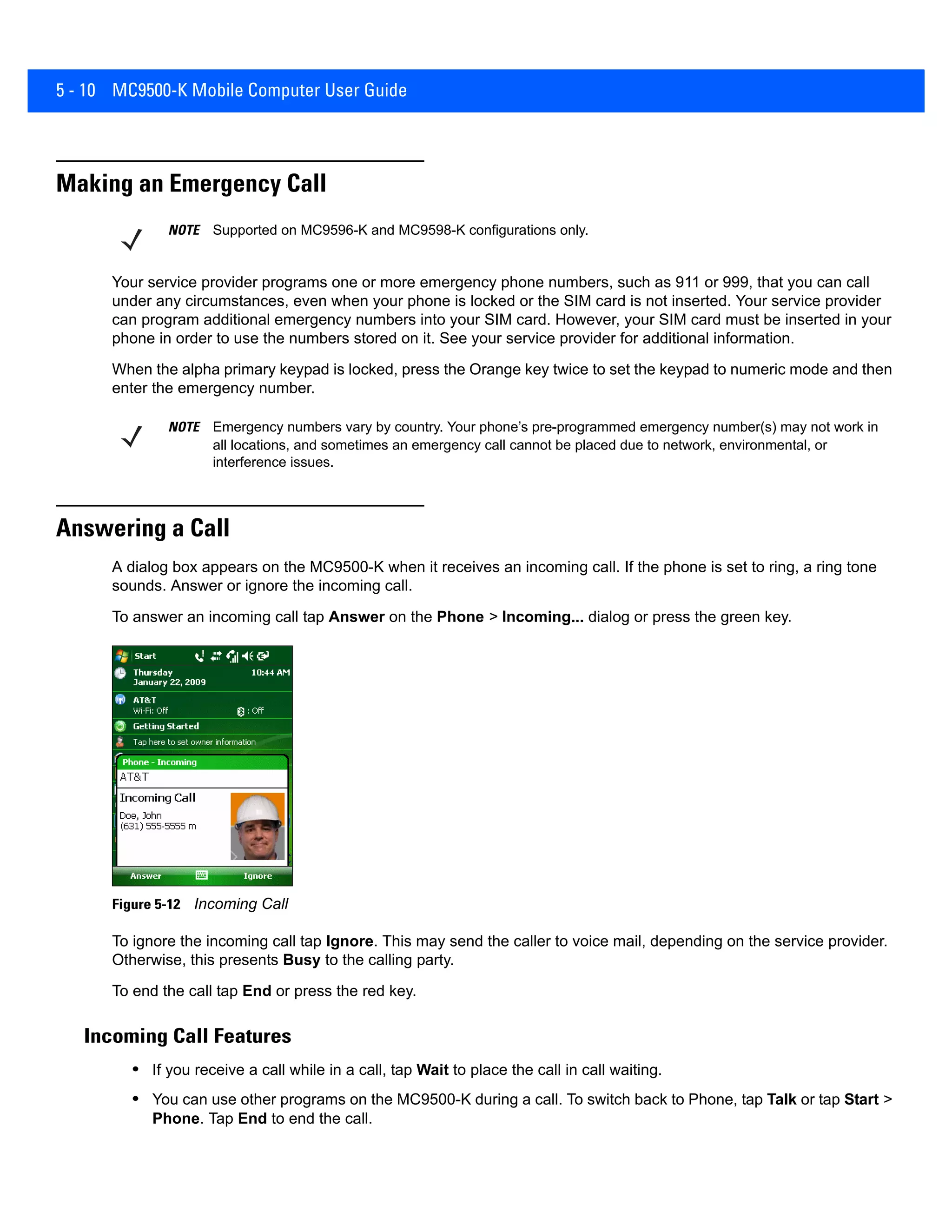
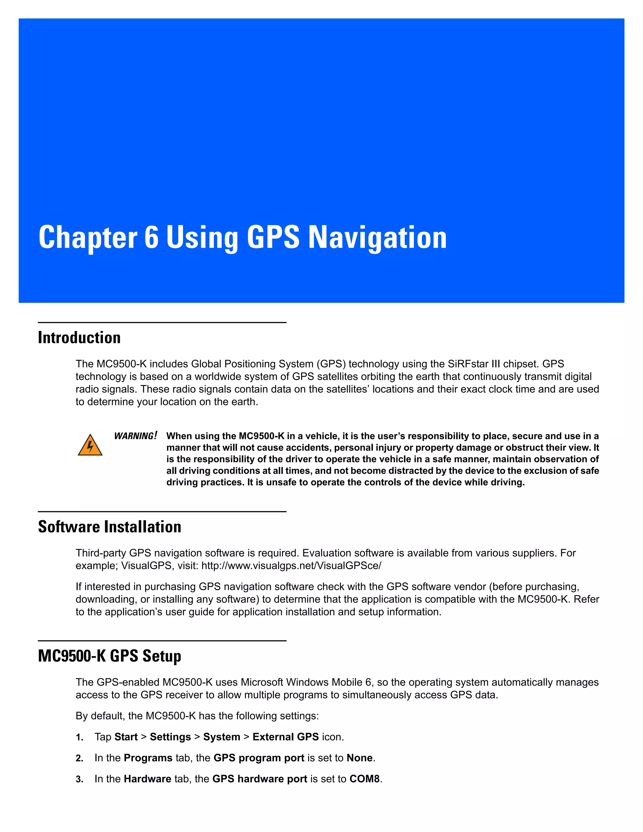
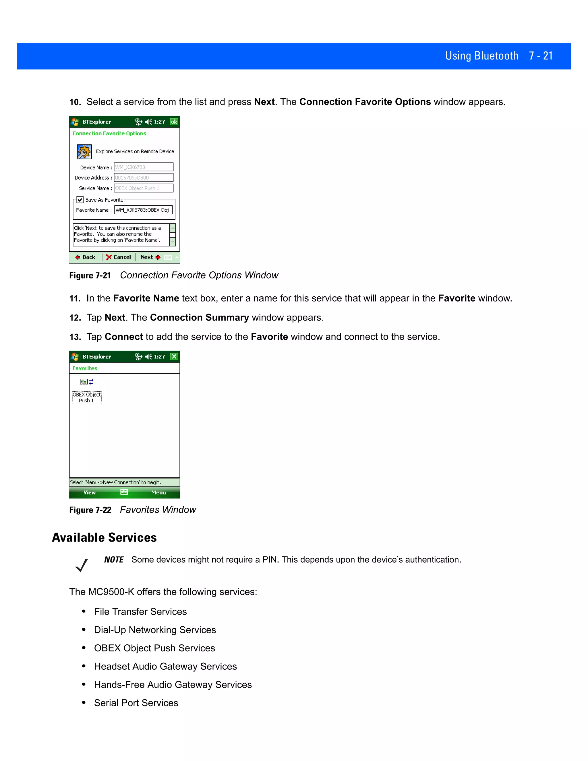
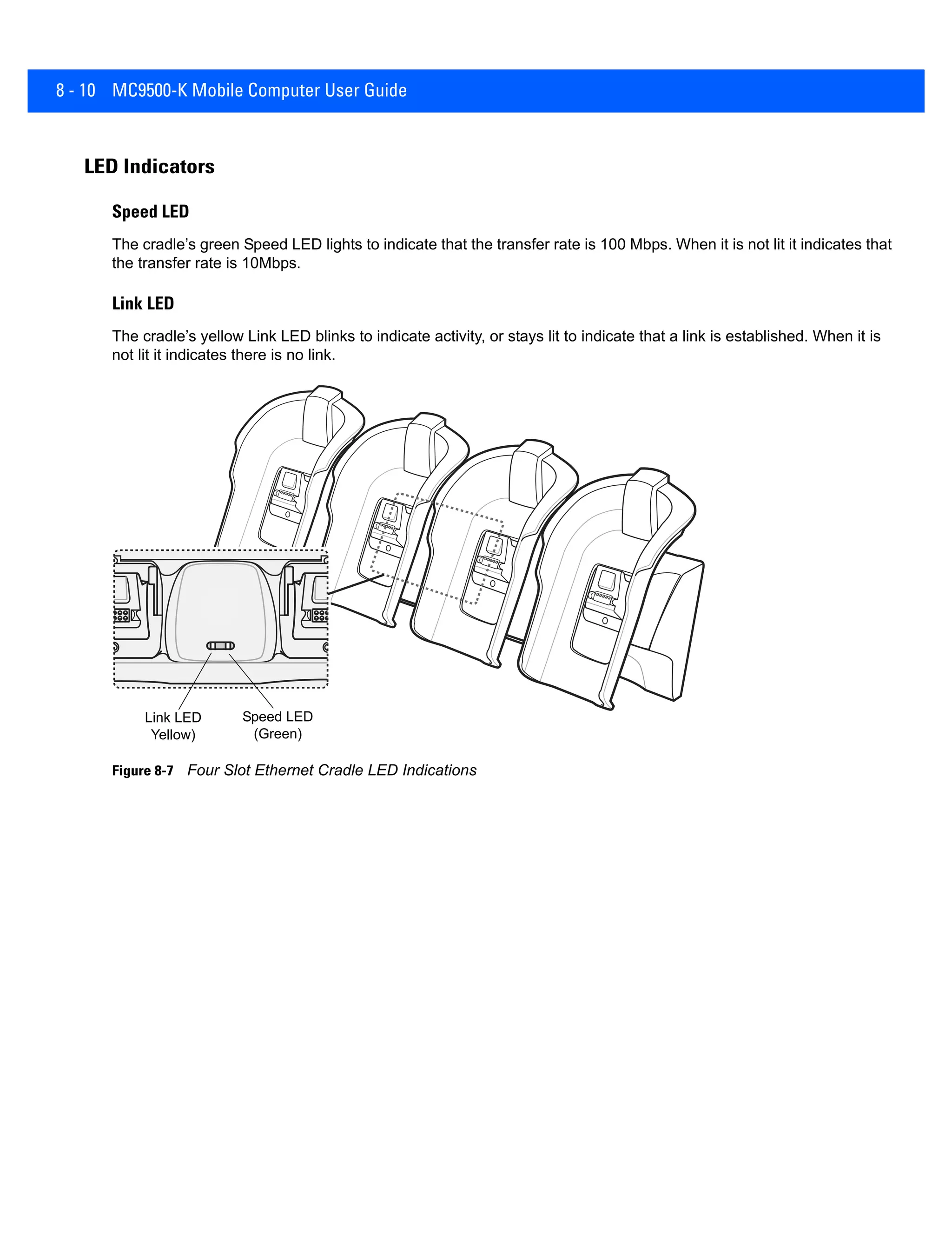
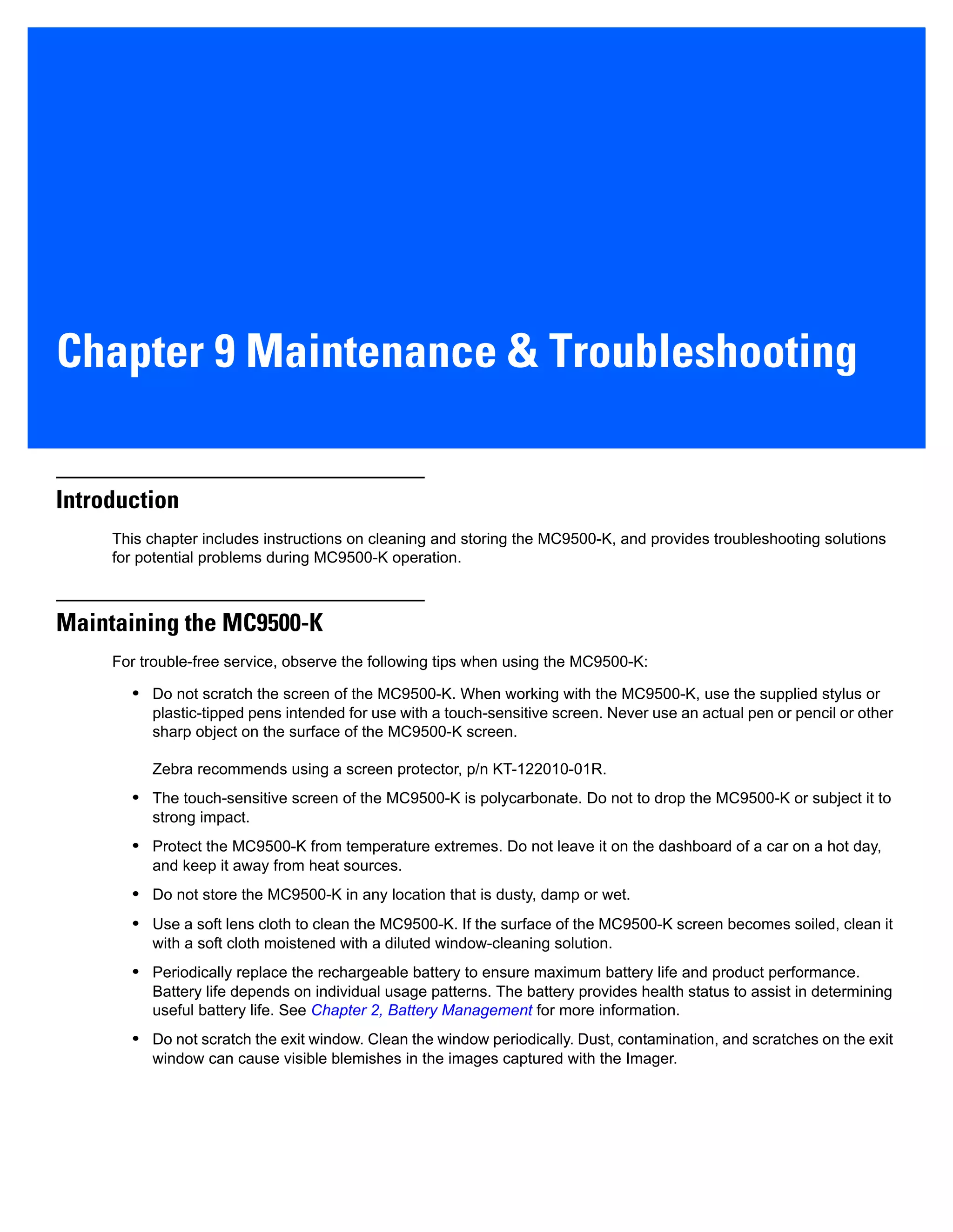
Smart Dialing
Smart Dialing makes it easy to dial a phone number. When you start entering numbers or characters, Smart Dialing
automatically searches and sorts the contact entries on the SIM card, in Contacts, and the phone numbers in Call
History (including incoming, outgoing, and missed calls). You can then select the desired number or contact from
the filtered list to dial.
Open the Phone screen, then tap the keys on the Phone keypad that correspond to the phone number or contact to
call. The contact panel lists contacts that match the sequence that you entered.
Smart Dialing starts looking for numbers or contacts that match the sequence entered.
To find a phone number:
• Enter the first one or two digits to find a phone number in Call History.
• Enter the first three digits or more to find a phone number from the saved Contacts and SIM card.
To find a contact name:
• Enter the first letter of a contact’s first name or last name. Smart Dialing searches for the letter starting
from the first character of a contact name as well as from the character that appears after a space, dash,
or underscore in a contact name. For example, if you tap number “2” which is associated with [a, b, c] on
the Phone keypad, contact names such as the following will be considered matches: “Smith, Bernard”,
“Adams, John”, “Carlson, Eileen”, “Dillon, Albert”, “Childs, Larry”, “Cooper, Robert” and “Parks, Celine”.
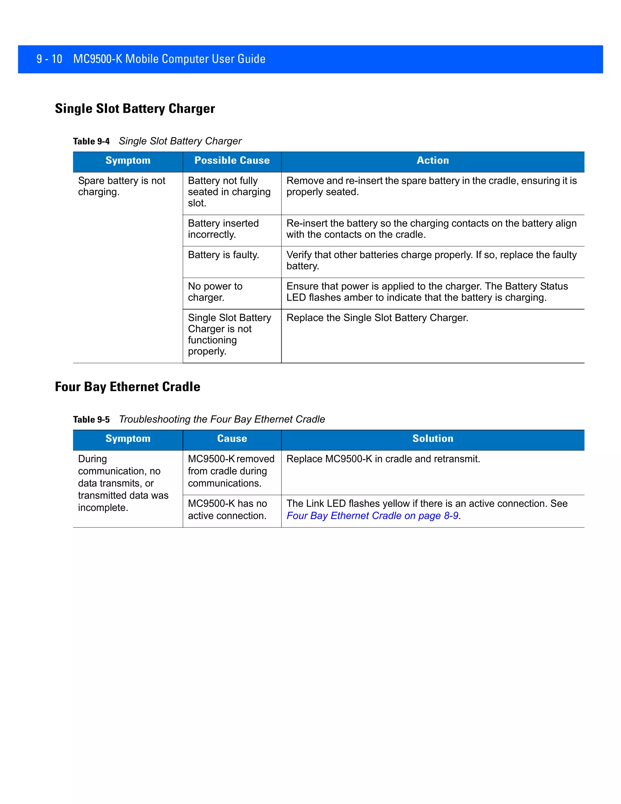
• If the matching list is long narrow down the search further by entering another letter. Using the same
example above, tap “3” which is associated with (d, e, f), the matching list is narrowed down to the
following names: “Smith, Bernard”, “Adams, John”, and “Parks, Celine”.
Figure 5-13 Finding a Contact](https://image.slidesharecdn.com/zebramc9500-k2dindustrialpdausermanualhionit-190726042310/75/PDA-Zebra-MC9500-K-2D-PDA-PDA-99-2048.jpg)


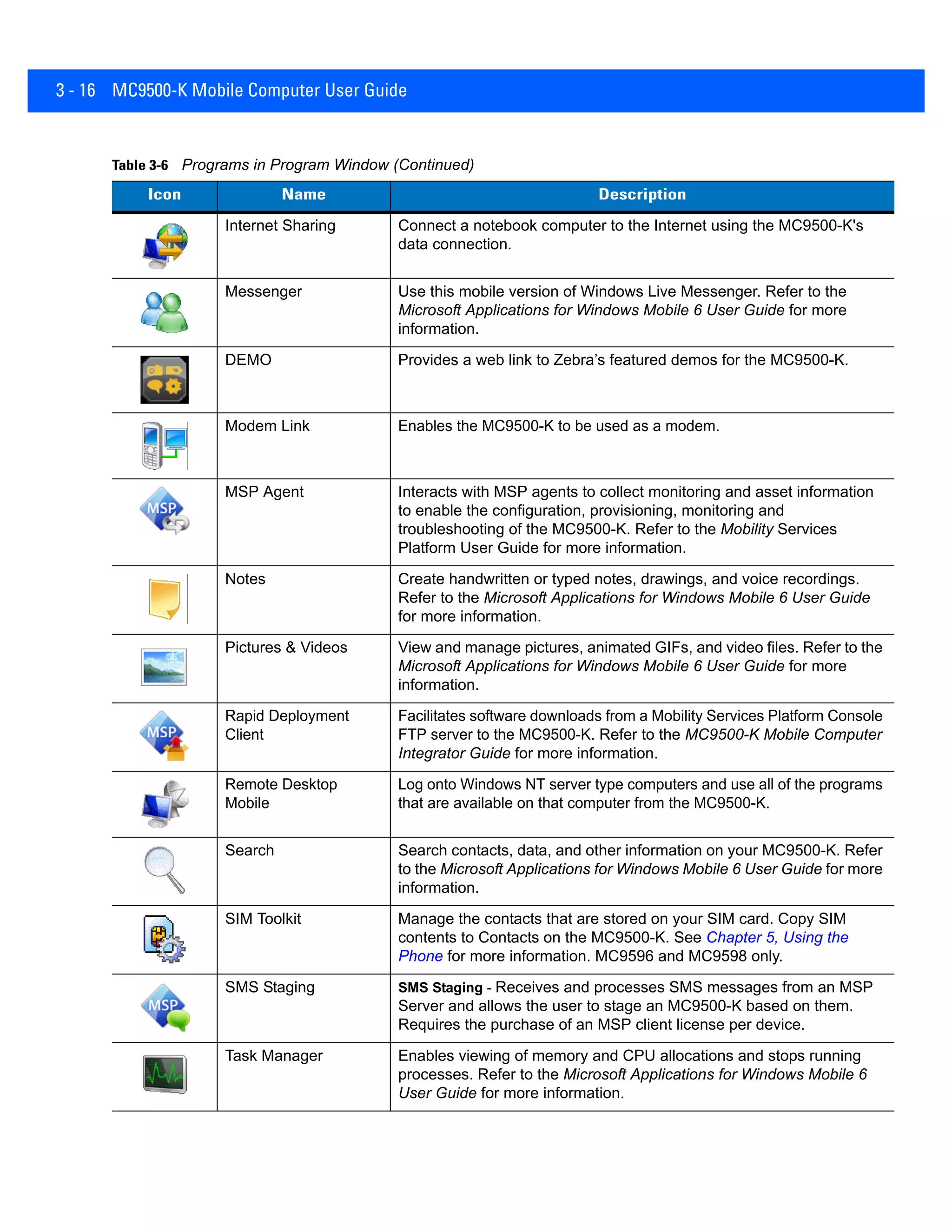
The MC9500-K Mobile Computer User Guide details the setup, usage, and maintenance of the device, along with licensing terms for the included software. The guide includes sections on battery management, data capture, phone usage, GPS navigation, Bluetooth functionality, and troubleshooting. It is a comprehensive manual designed to assist users in effectively operating and maintaining their MC9500-K mobile computer.


![Vibe Coding vs. Spec-Driven Development [Free Meetup]](https://cdn.slidesharecdn.com/ss_thumbnails/vibecodingvsspecdrivendevelopment-251209105622-43f455e7-thumbnail.jpg?width=640&height=640&fit=bounds)


