Download to read offline
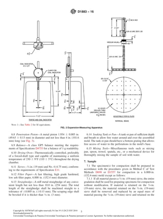
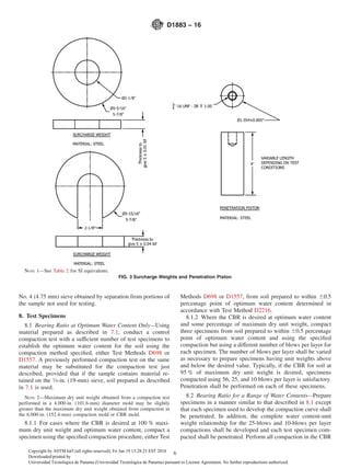
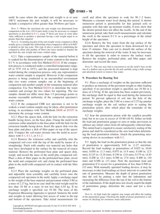
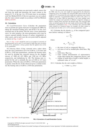
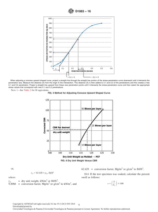
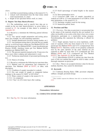
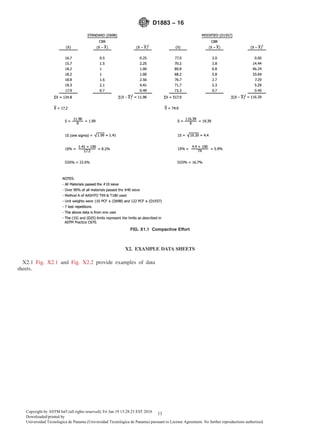
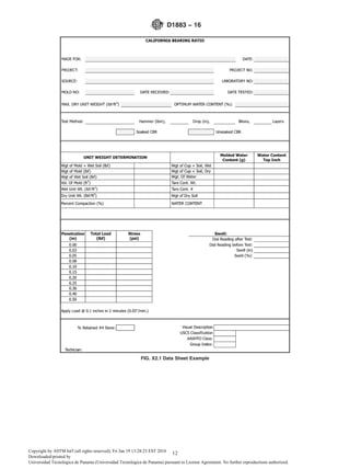
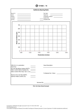

This document describes the standard test method for determining the California Bearing Ratio (CBR) of laboratory-compacted soils. The CBR test evaluates the strength of subgrade, subbase, and base materials for pavement design. The test involves compacting soil specimens to a specified density and water content then measuring the penetration of a piston under increasing loads. The CBR value is the ratio of the load required to penetrate the soil to the load required for a standard crushed stone material. The test method specifies the required apparatus, procedures, calculations and provides guidance on interpreting and applying CBR values.


