Downloaded 210 times


![CYME 5.02 – Equipment Reference Manual
CHAPTER 8 – STATIC VAR COMPENSATORS 77
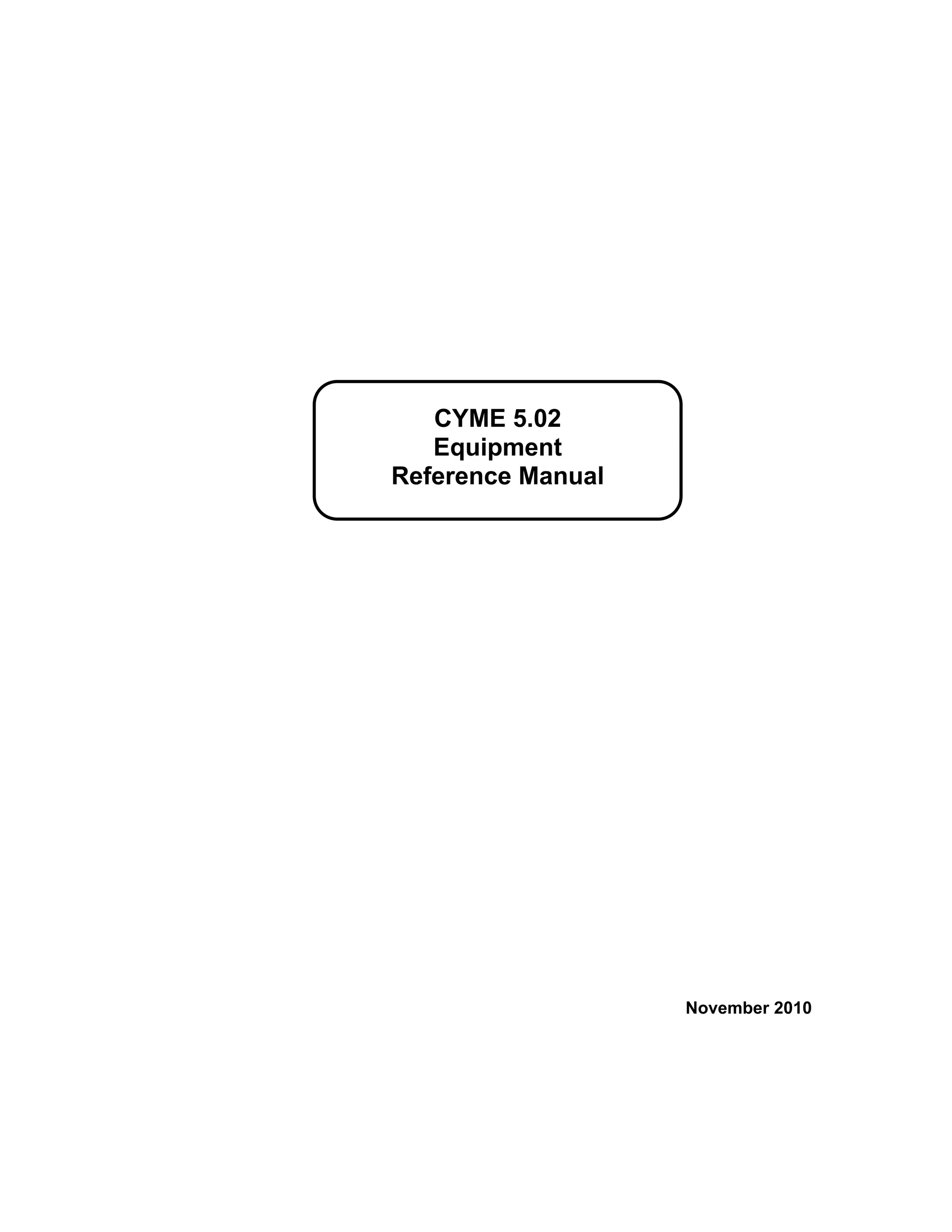
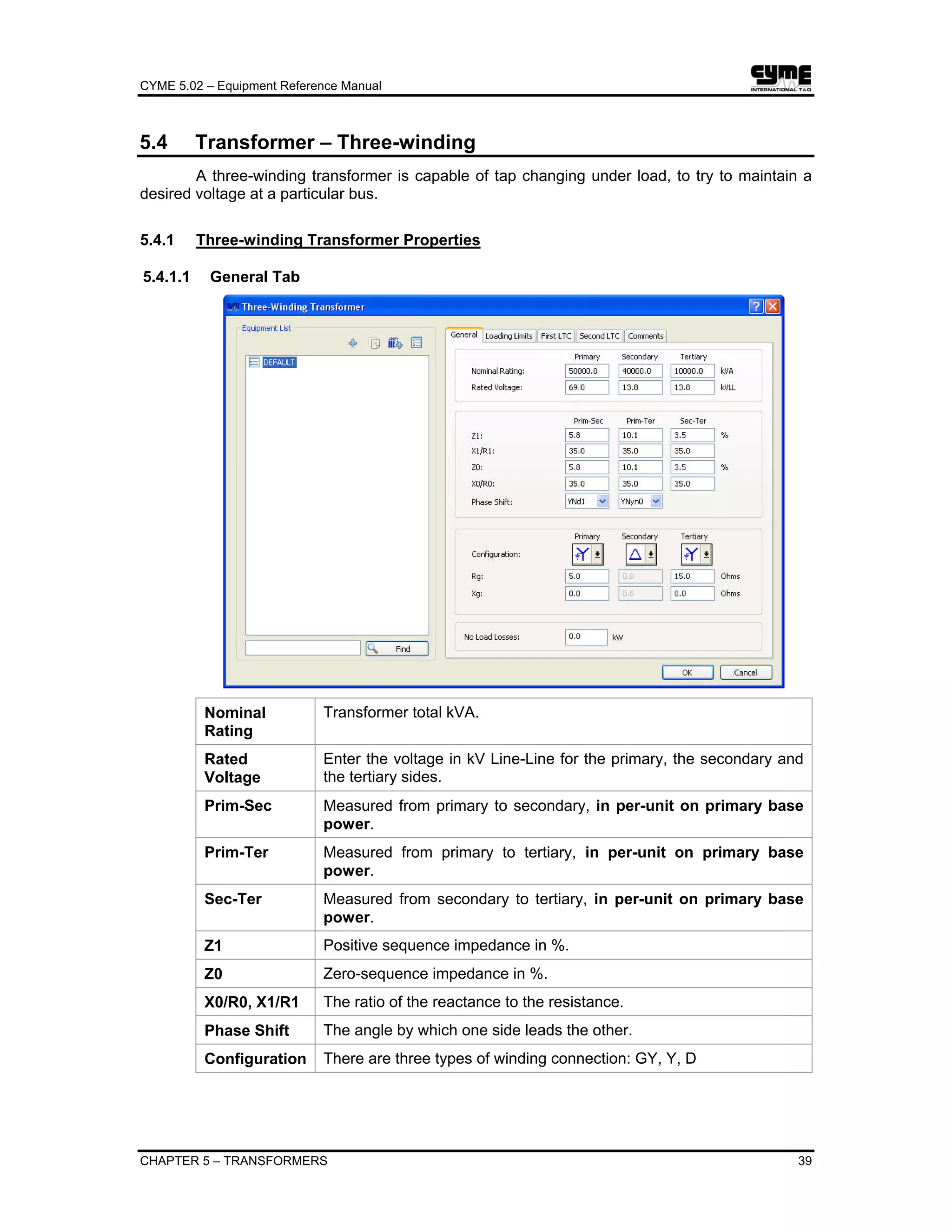
Chapter 8 Static Var Compensators (SVC)
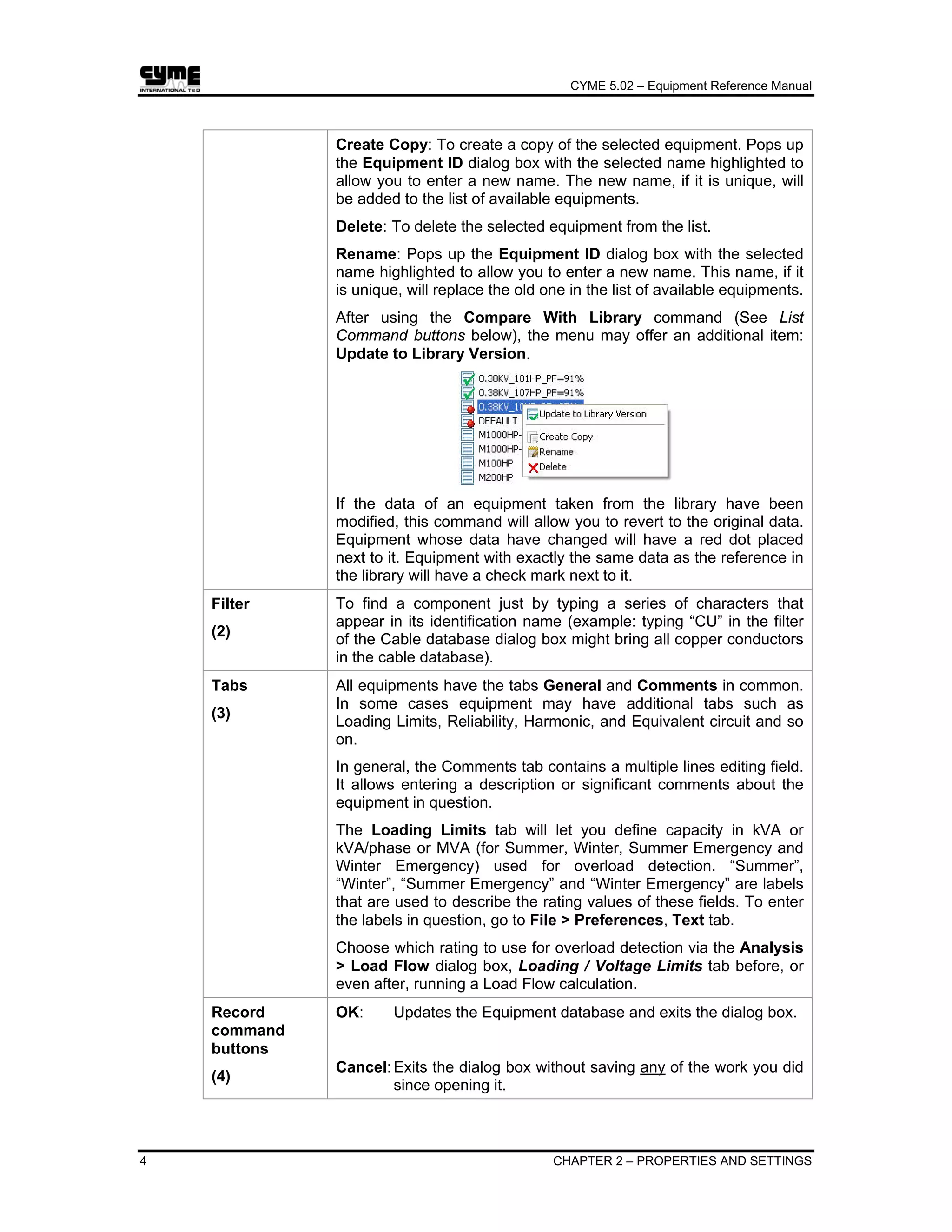
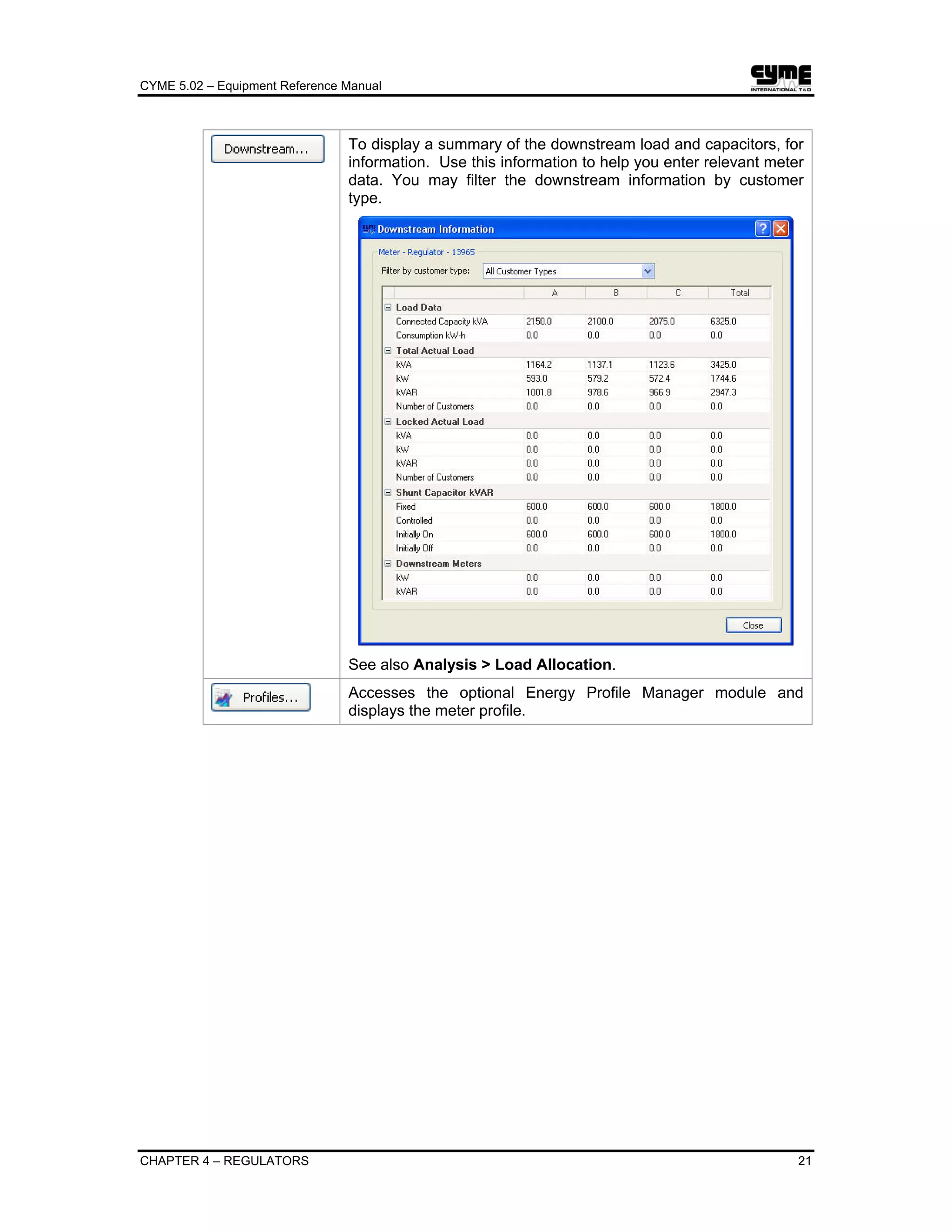
Static Var Compensators are shunt capacitors and/or reactors which are controlled by
power electronic circuits so that the reactive power they absorb or furnish is continuously
adjustable over a given range [Qmin,Qmax]. They are used for voltage control where the
reactive power demand varies considerably.
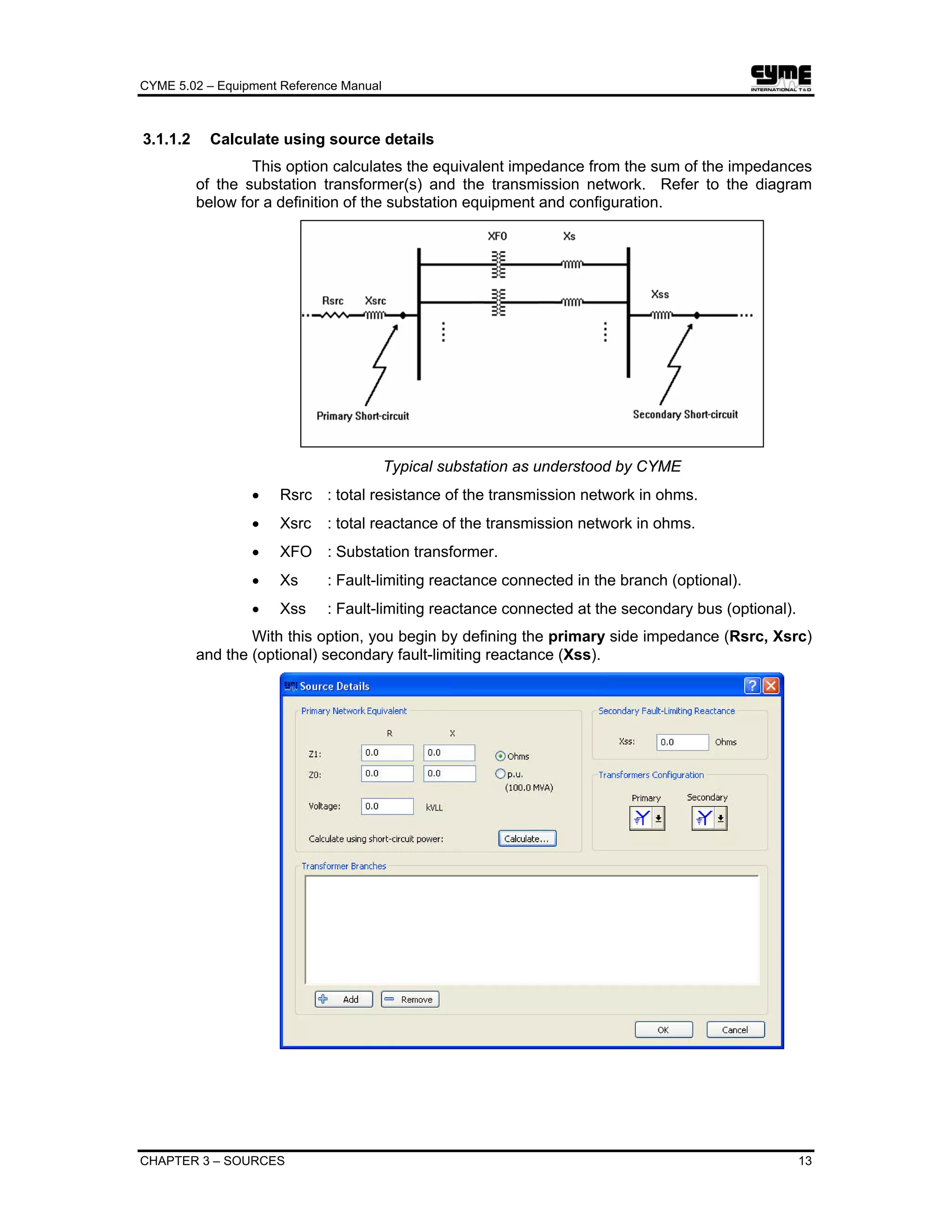
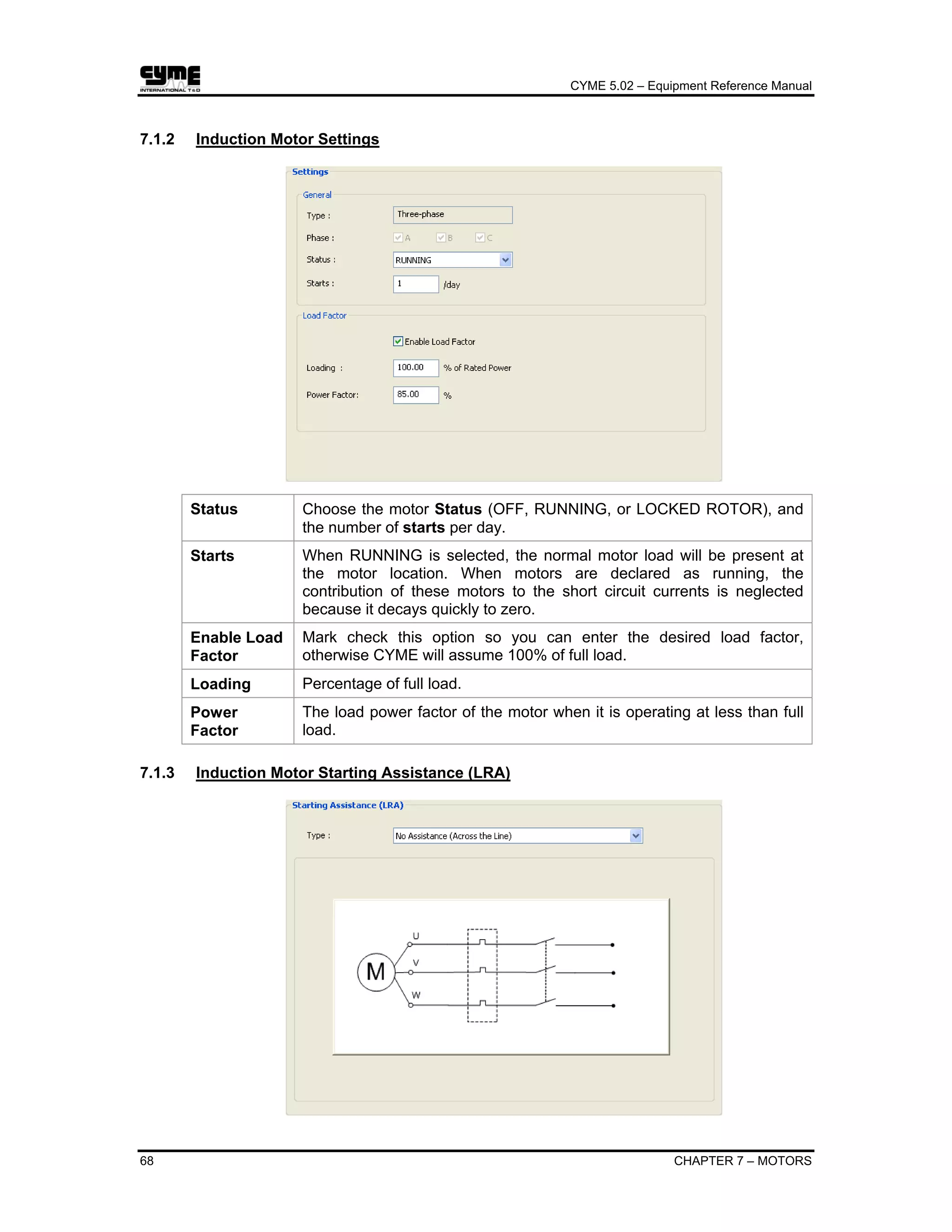
8.1 SVC Properties
Number of
Pulse
Must be a multiple of 6.
Rated Voltage Nominal voltage in kilovolts.
Minimum /
Maximum
Reactive Power
Lower and upper limits of VAR injection. Qmin can be negative,
so that the SVC can absorb VARs.](https://image.slidesharecdn.com/cymeequipmentreferencemanual-161114044816/75/Cyme-equipment-reference-manual-85-2048.jpg)


![CYME 5.02 – Equipment Reference Manual
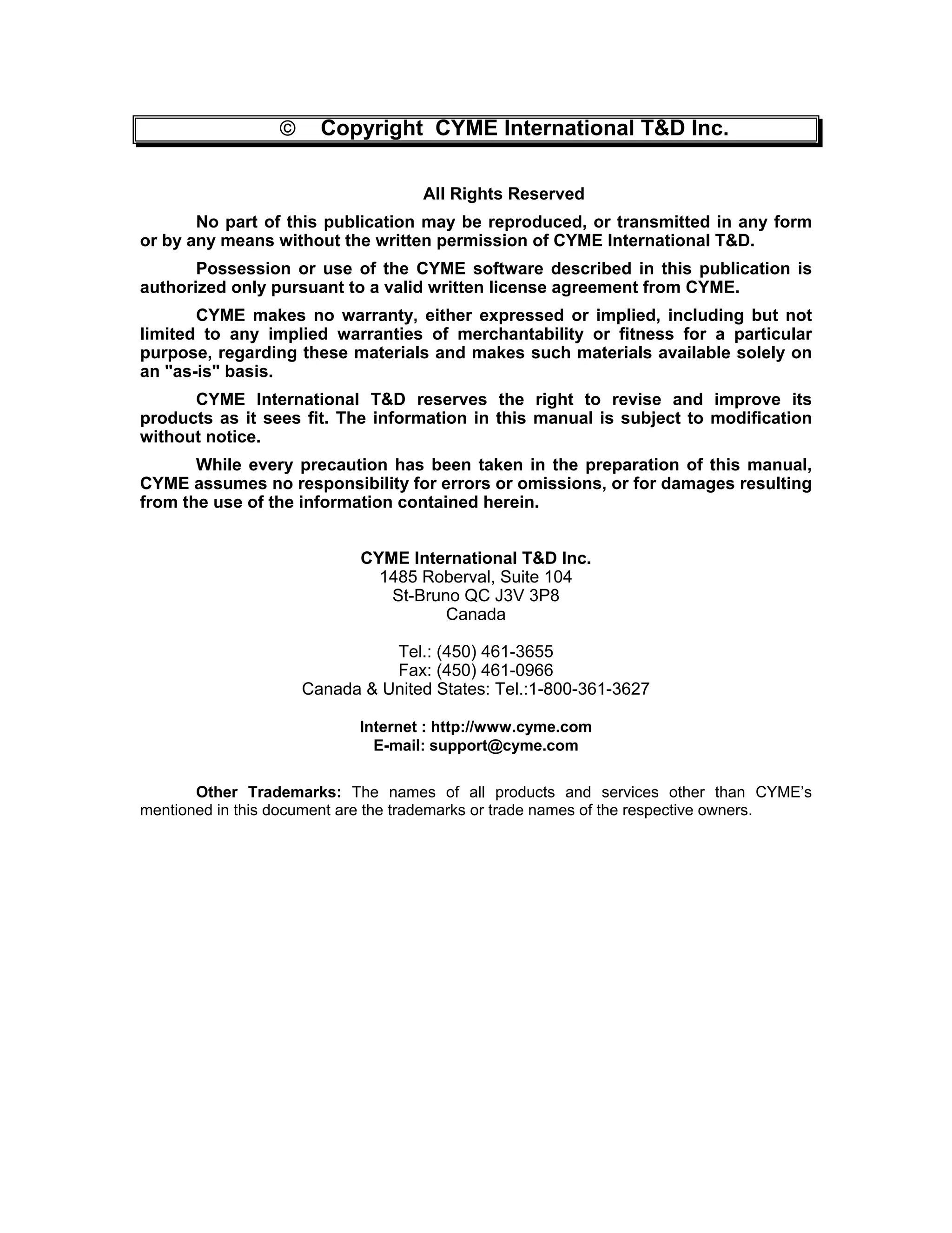
102 CHAPTER 12 – SOLID OXIDE FUEL CELLS
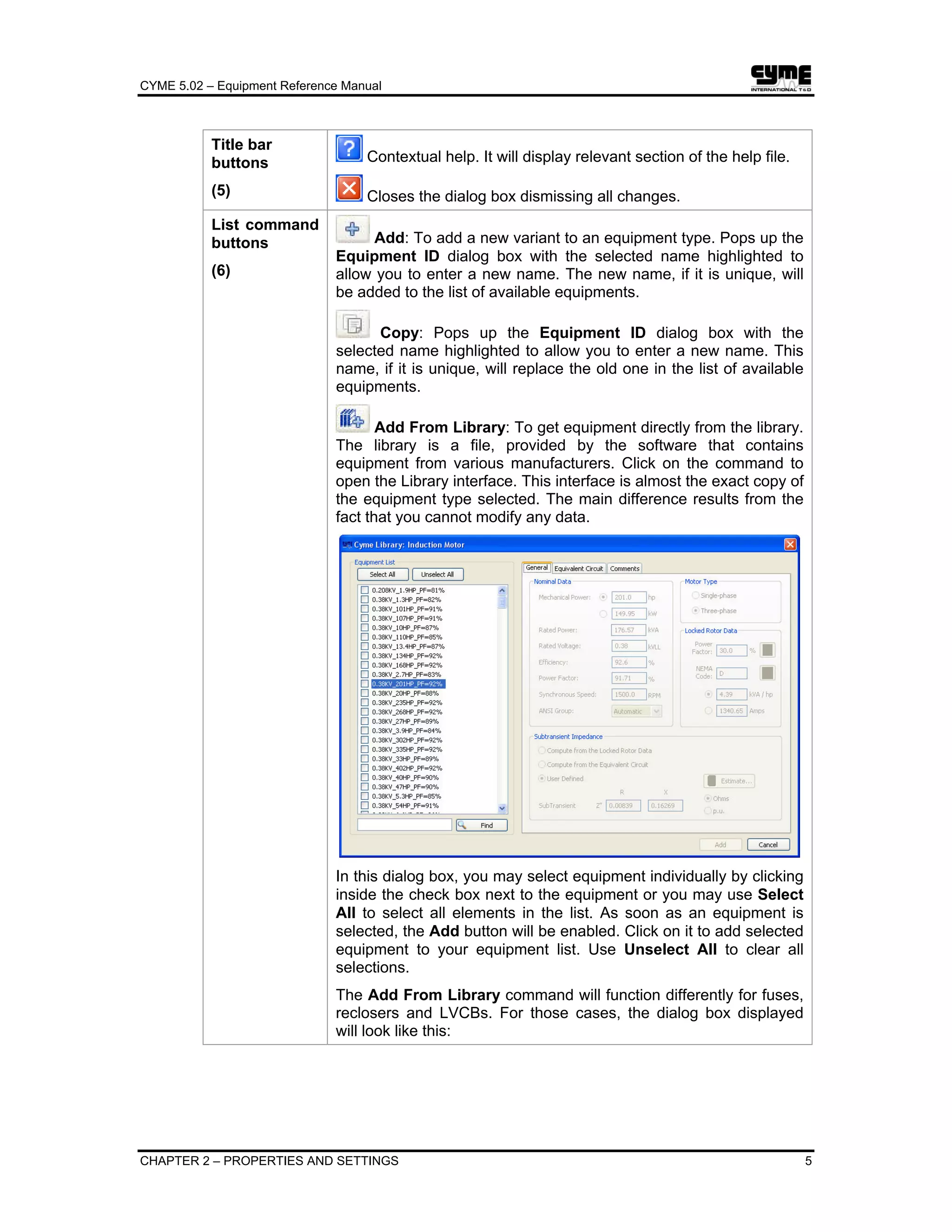
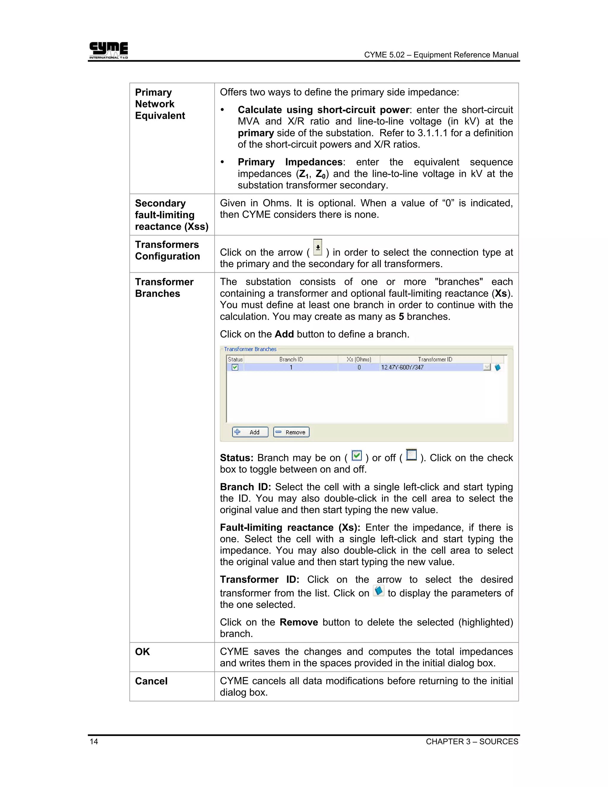
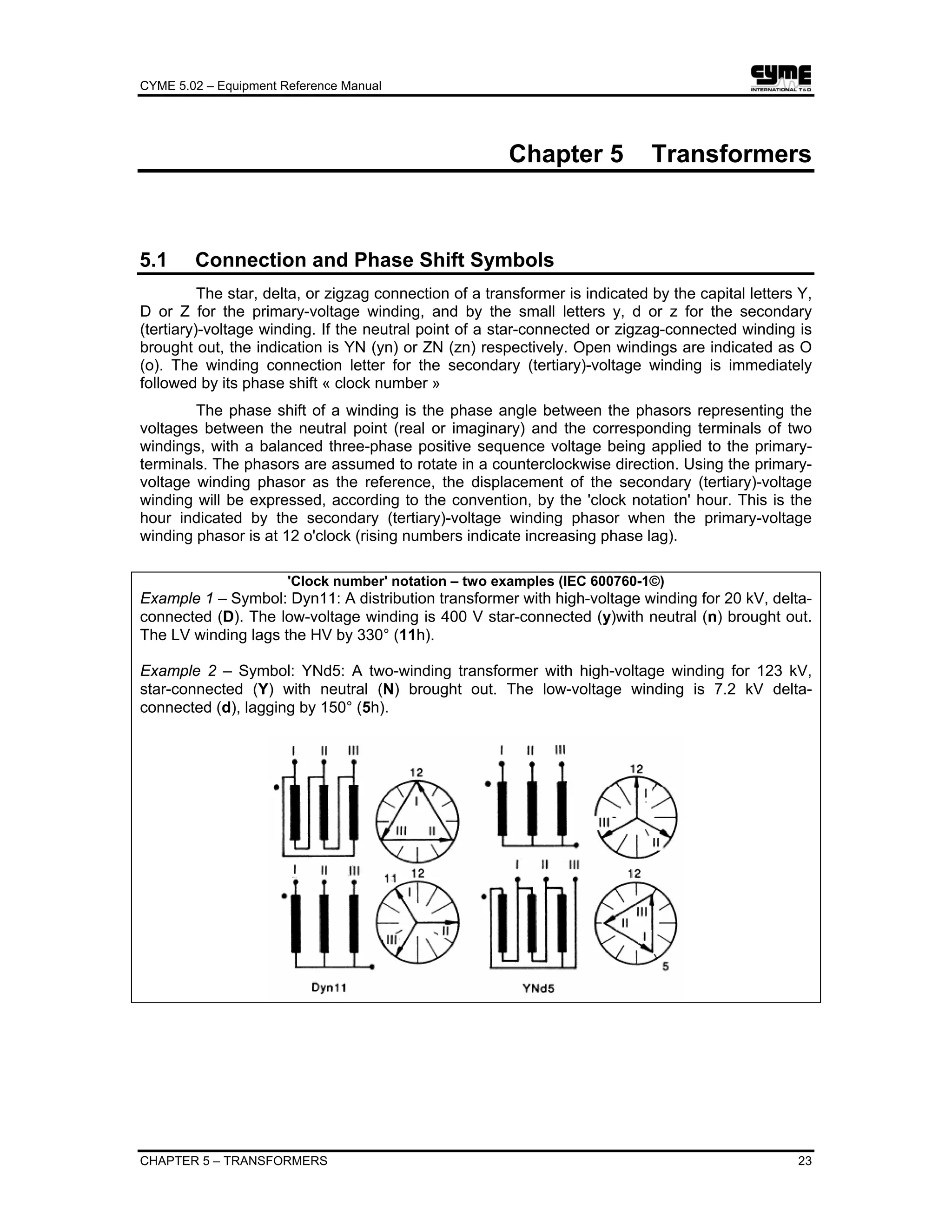
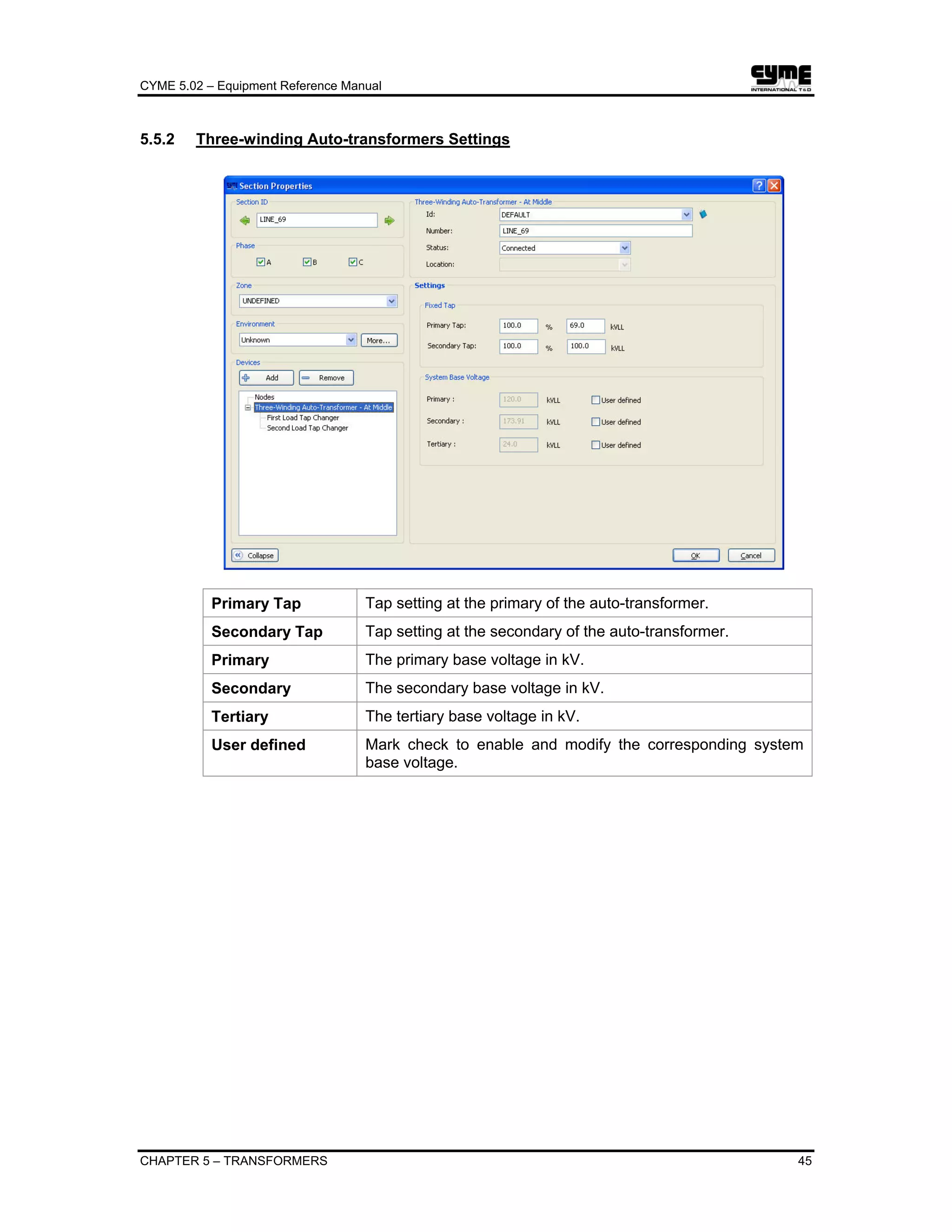
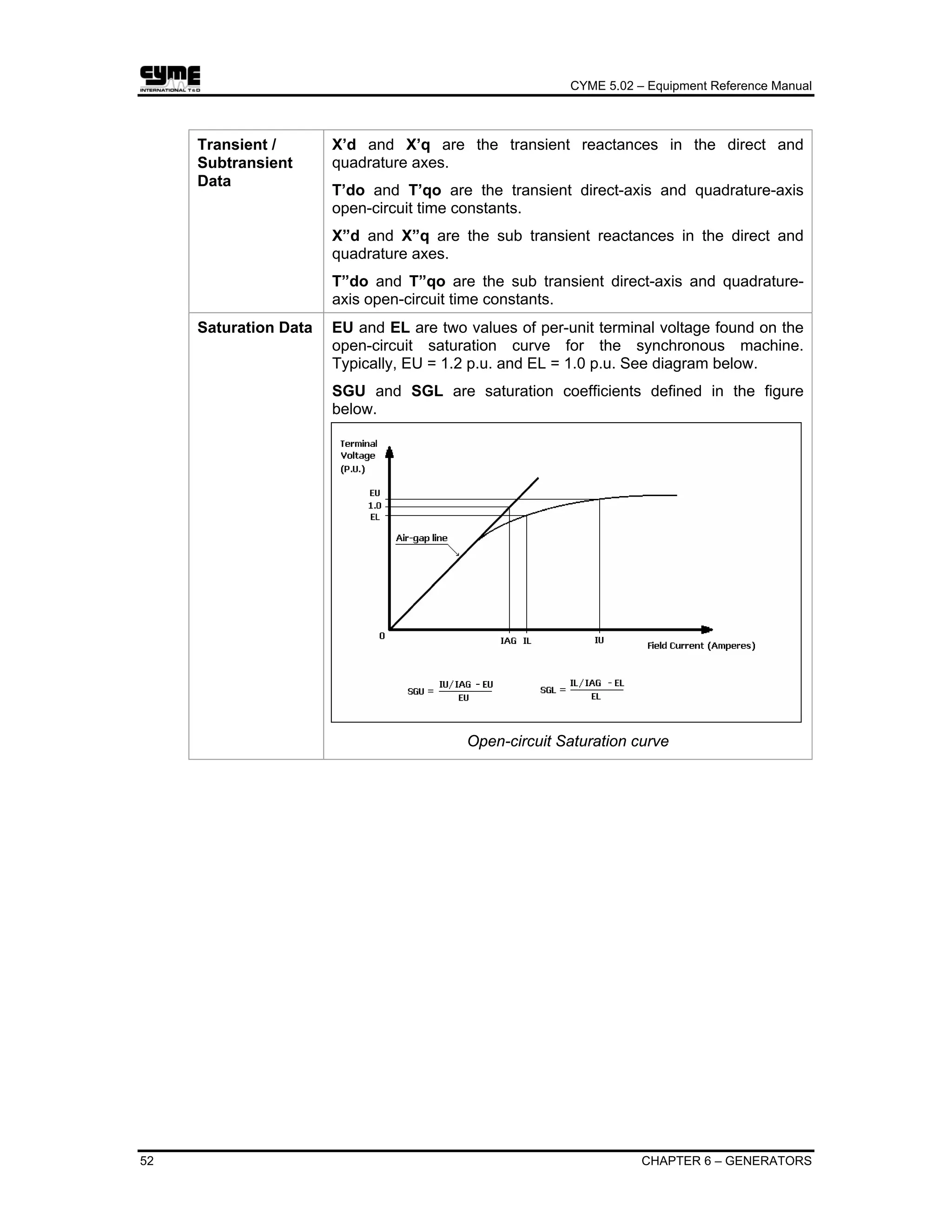
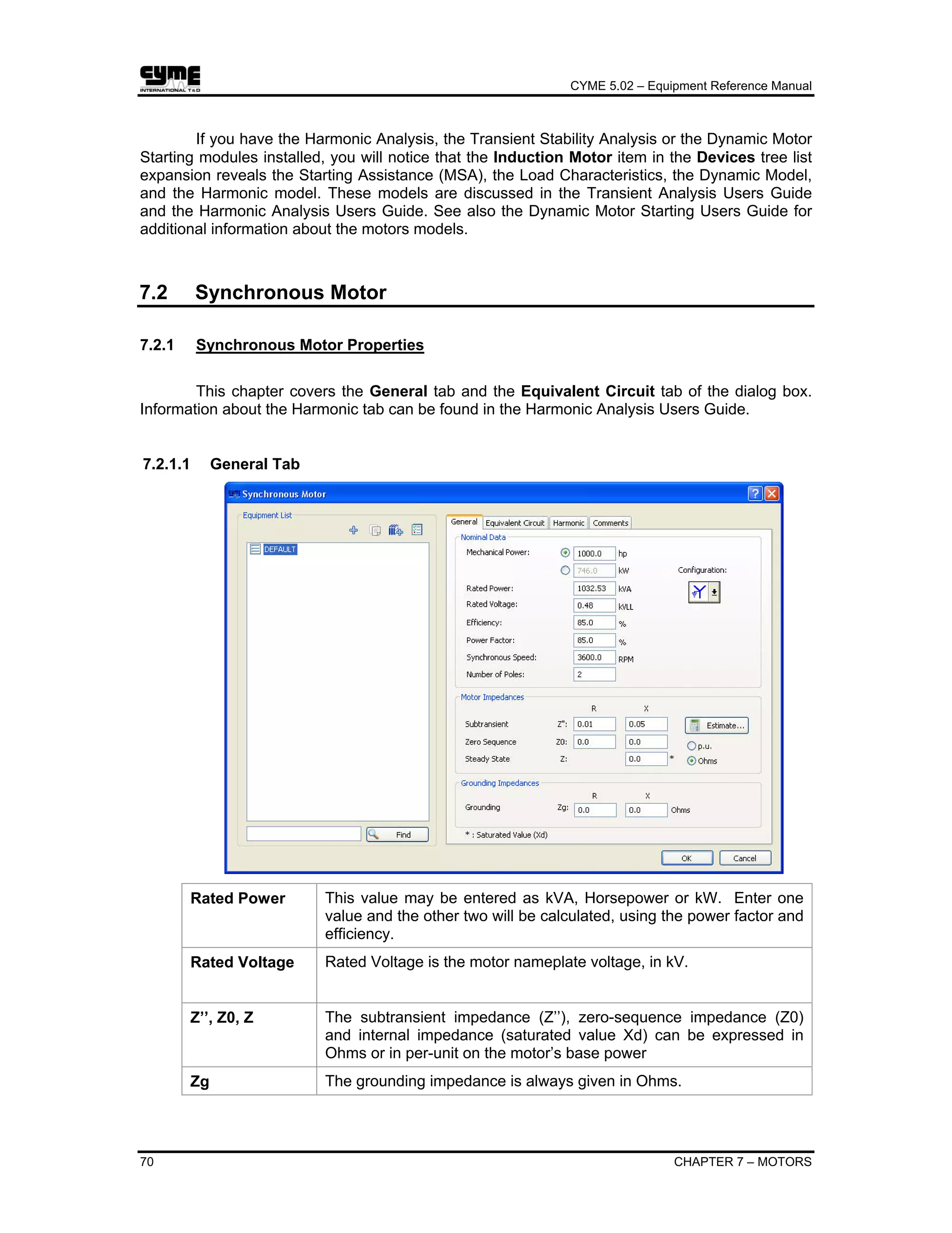
Most fuel cells produce less than the application required voltage. Therefore, multiple
cells must be assembled into a fuel cell stack to boost the voltage.
The stack output voltage fcv is described by the Nerst equation. The
r
fcri term is the
ohmic loss. This is the loss due to the resistance of the electrodes and to the resistance of the
flow of 2O ions through the electrolyte.
r
fc
OH
OH
fc ri
P
pp
F
RT
ENV −
⎥
⎥
⎦
⎤
⎢
⎢
⎣
⎡
⎟
⎟
⎠
⎞
⎜
⎜
⎝
⎛
+=
2
22
ln
2
00
Symbol Description
N0 Number of cells in series in the stack
E0 Ideal standard potential which the open cell voltage in the standard
operating conditions (temperature = 25 0
C and a pressure of 1 atmosphere)
r Ohm losses in the stack
R [J/kmol-K] Universal gas constant
T [K] Absolute temperature
F [C/mol] Faraday’s constant
PH2 Partial pressure of Hydrogen
PO2 Partial pressure of Oxygen
PH2O Partial pressure of Water
12.1 Solid Oxide Fuel Cell Properties](https://image.slidesharecdn.com/cymeequipmentreferencemanual-161114044816/75/Cyme-equipment-reference-manual-110-2048.jpg)


![CYME 5.02 – Equipment Reference Manual
CHAPTER 21 – HARMONIC DEVICES 157
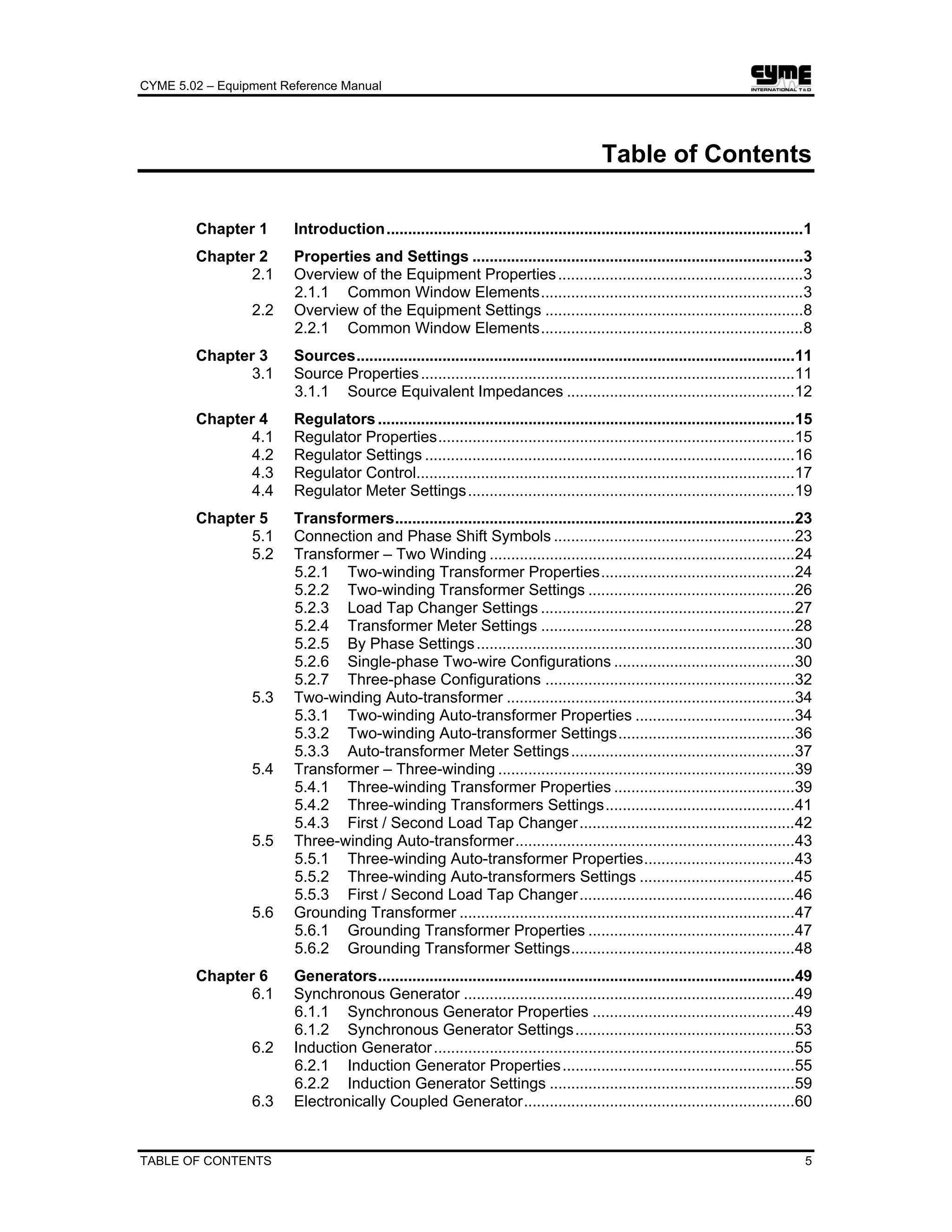
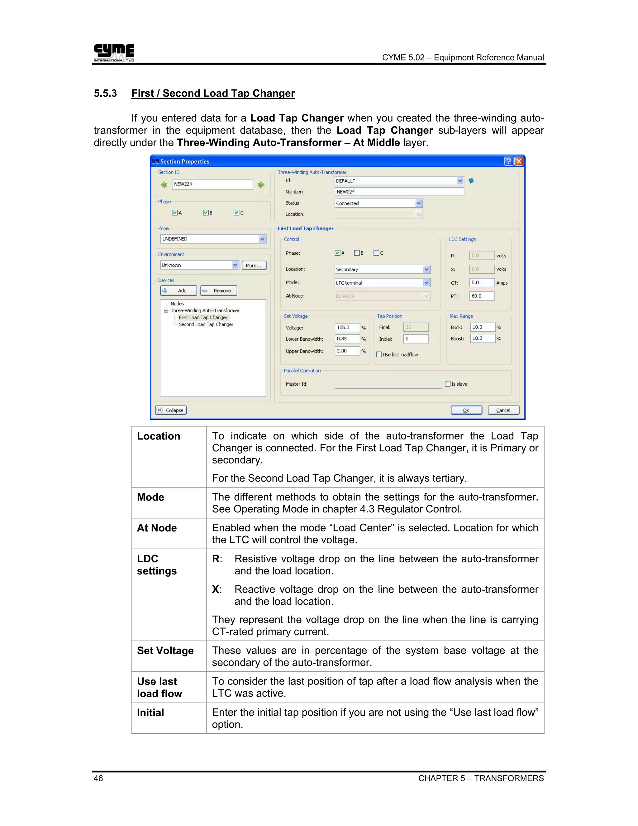
Chapter 21 Harmonic Devices
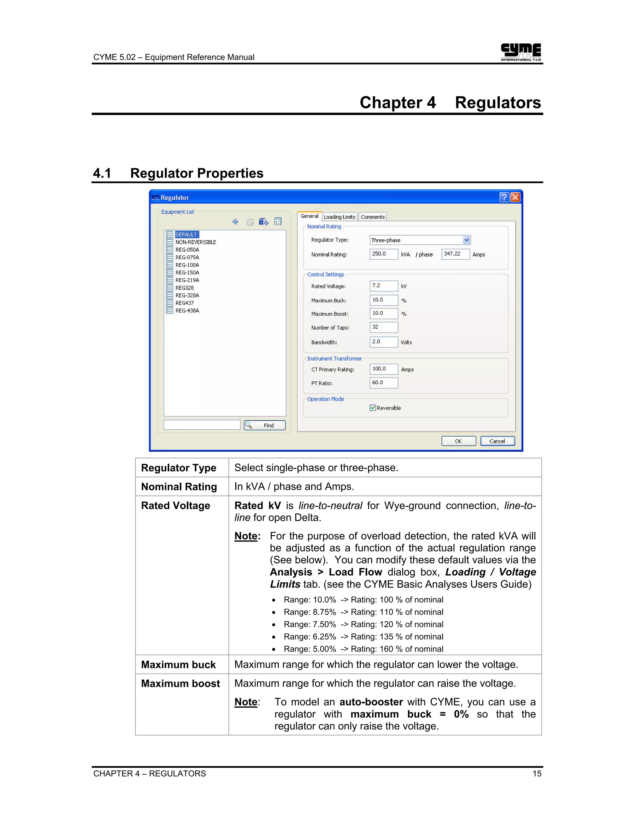
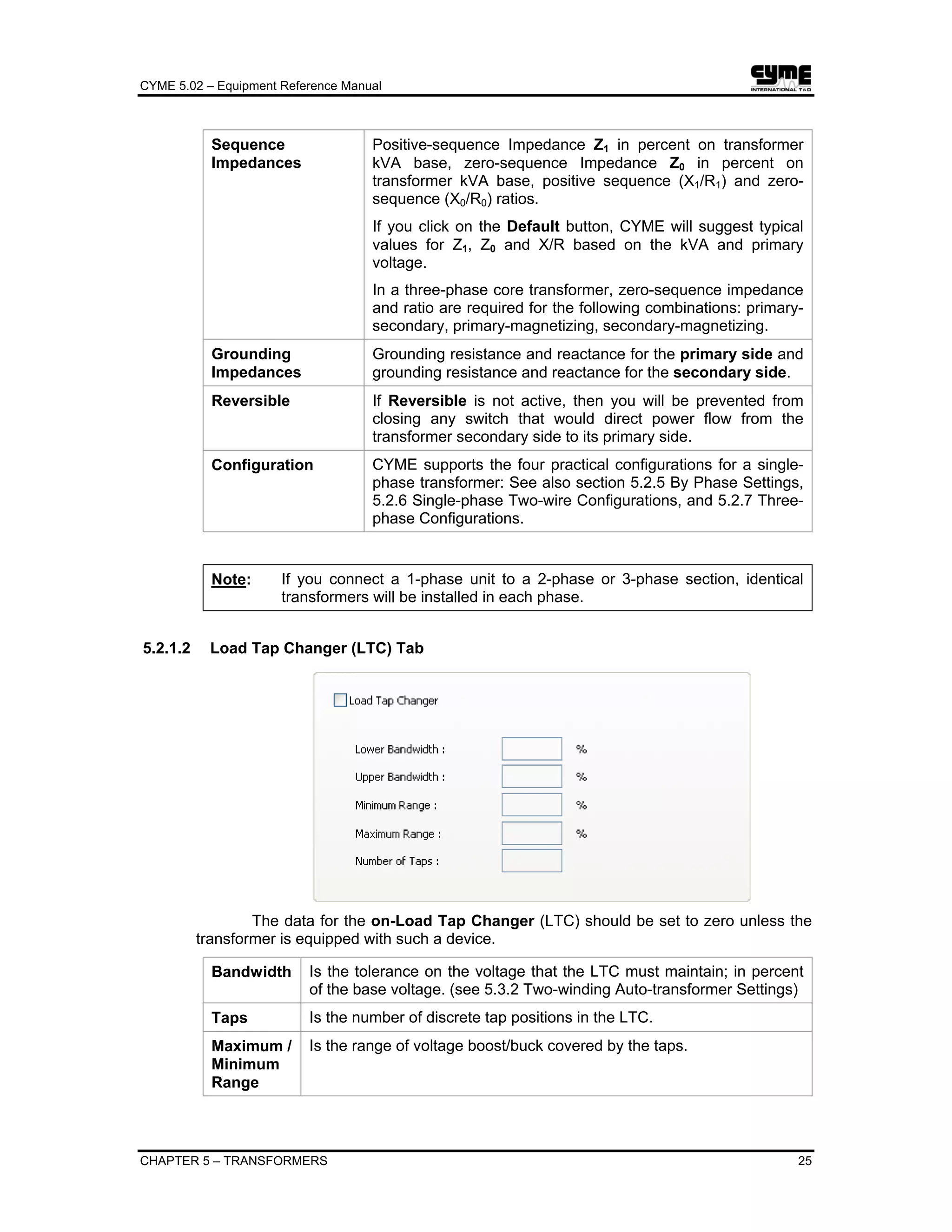
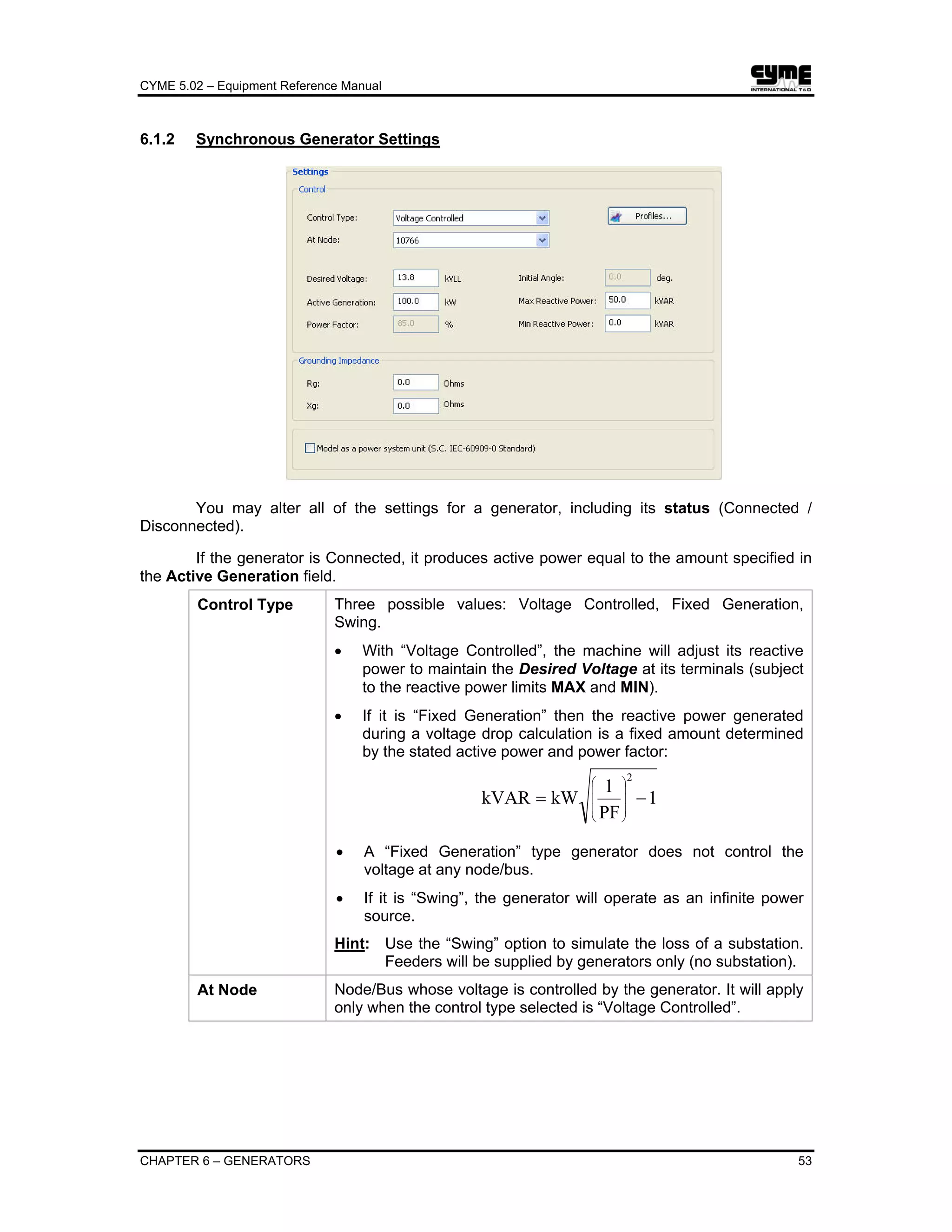
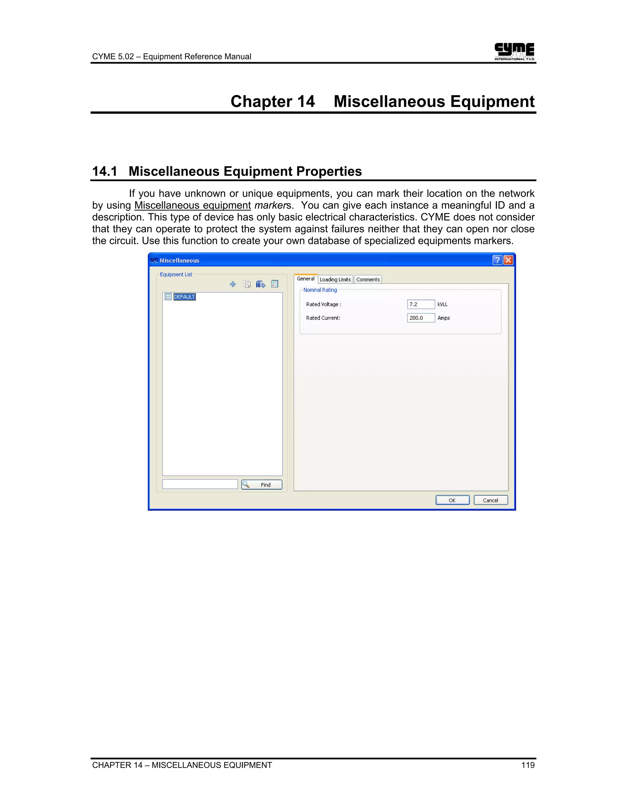
21.1 Frequency Source
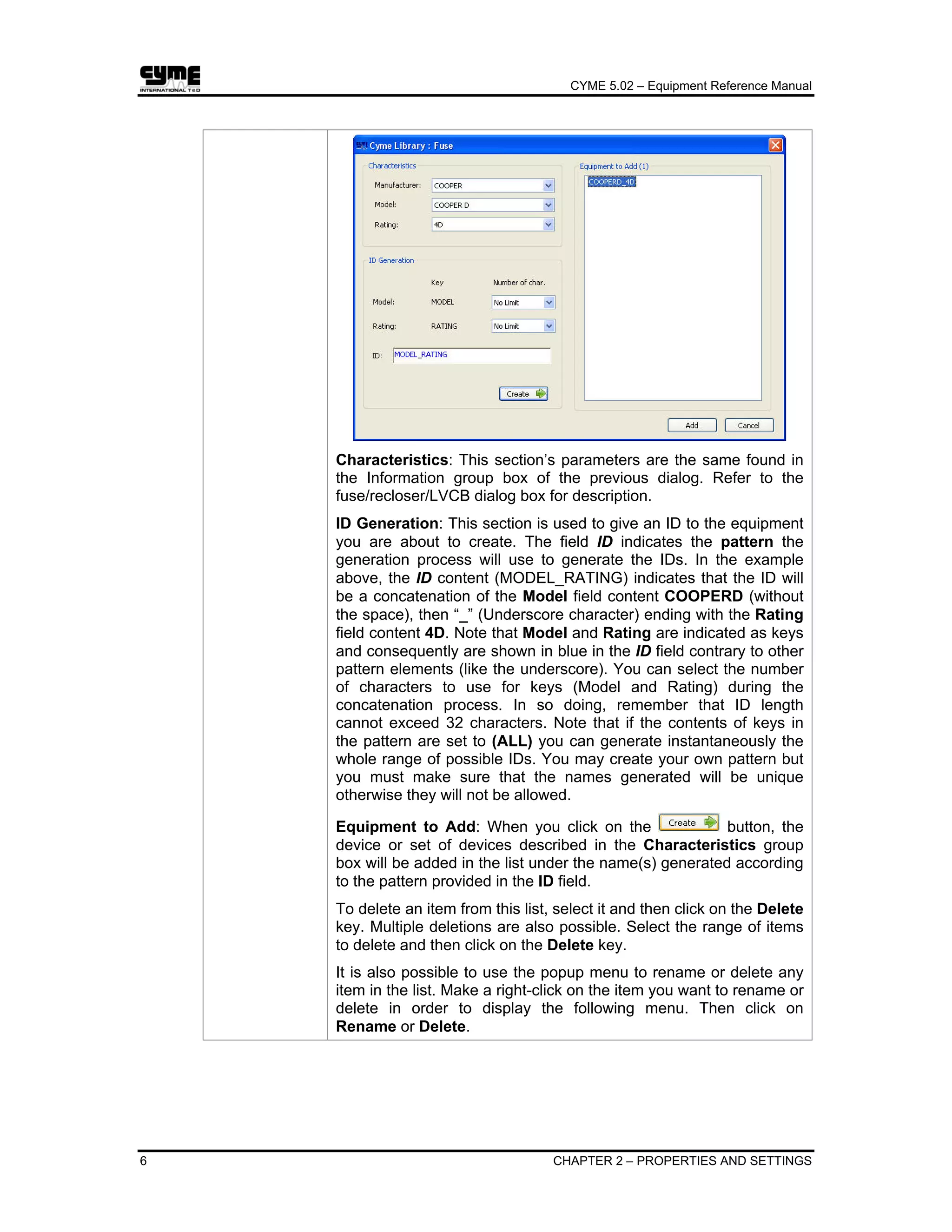
Select the menu option Equipment > Harmonic > Frequency Source to display the
corresponding dialog box.
This model is the general method to model any harmonic generating device. It requires
the current/voltage magnitudes in Amps/kV or in % of the current/voltage magnitude at the
fundamental frequency. You may enter currents comprising up to 100 frequencies. Click with the
mouse or use the <Tab> key to move to a field and type the number in. Press <Enter> to register
the number.
Source Type Current Source or Voltage Source
Harmonic Order Represents the vector of frequencies in per-unit of fundamental.
Current/Voltage
Magnitude [%] or
(Amps)/(kV)
Is the vector of current magnitudes (in Amp or in % of the
fundamental current magnitude).
Current/Voltage
Magnitude Units
To enter the current magnitude in % of the fundamental current
or in Amps, select the appropriate option in this group box.
Current Phase
Angle (o
)
Is the vector of phase angles (in degrees).](https://image.slidesharecdn.com/cymeequipmentreferencemanual-161114044816/75/Cyme-equipment-reference-manual-165-2048.jpg)


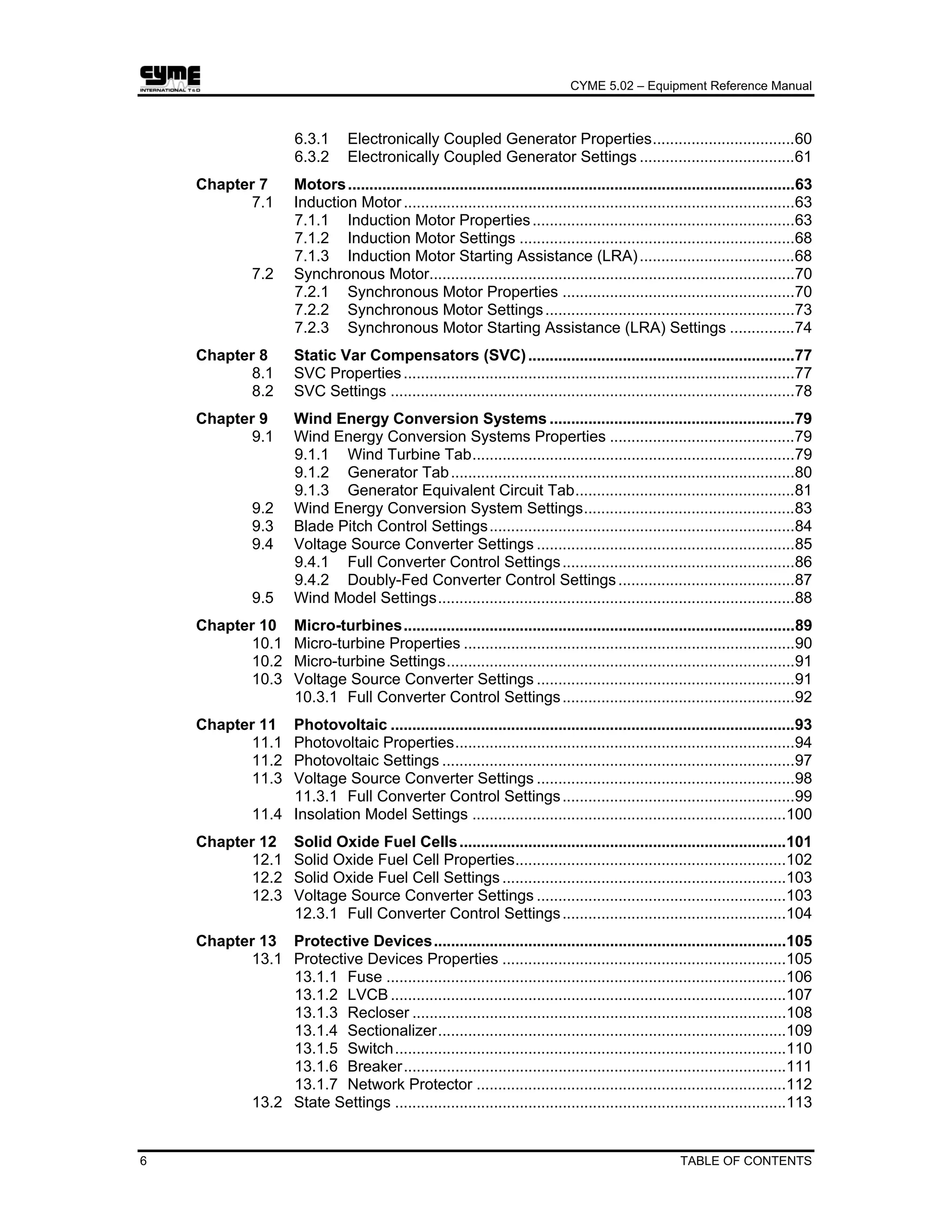
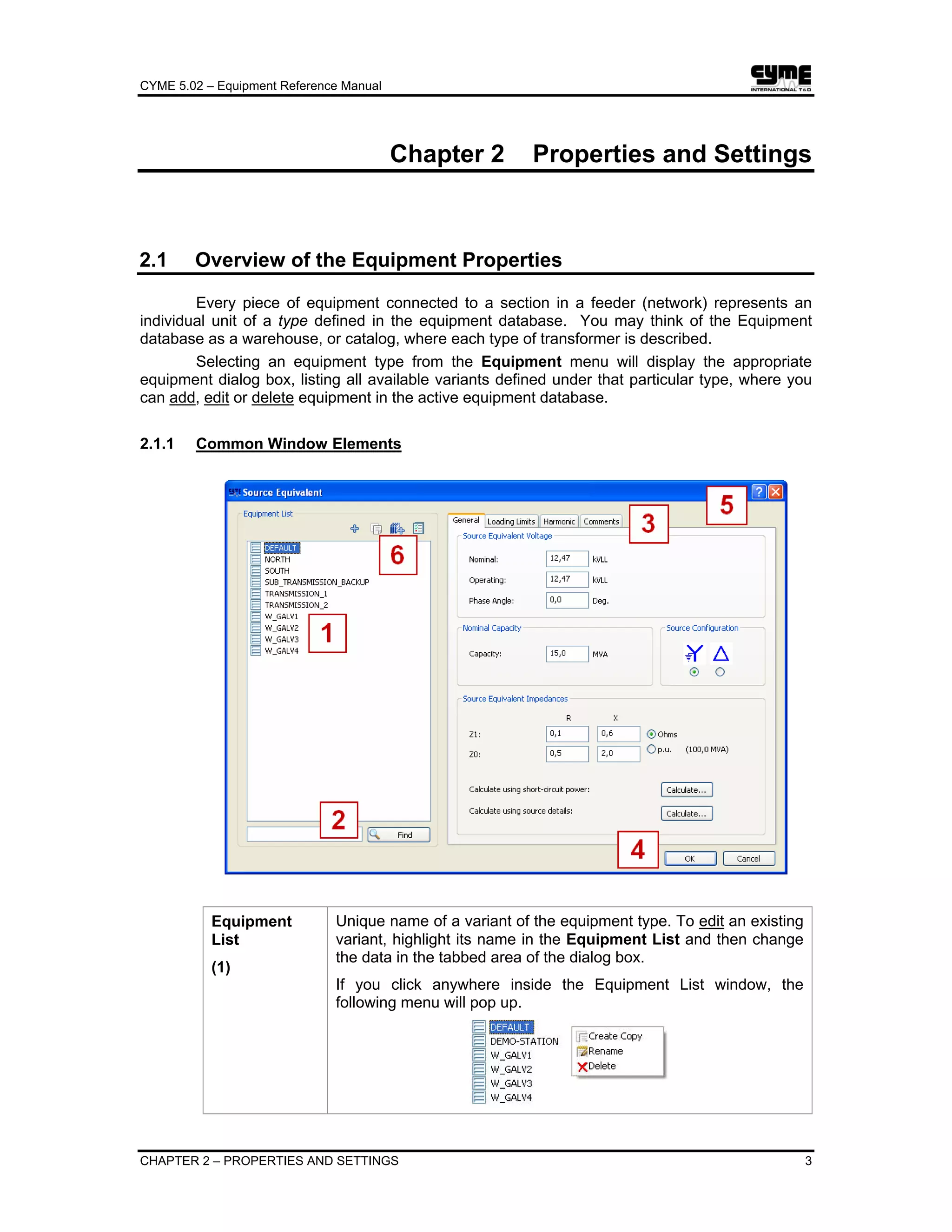
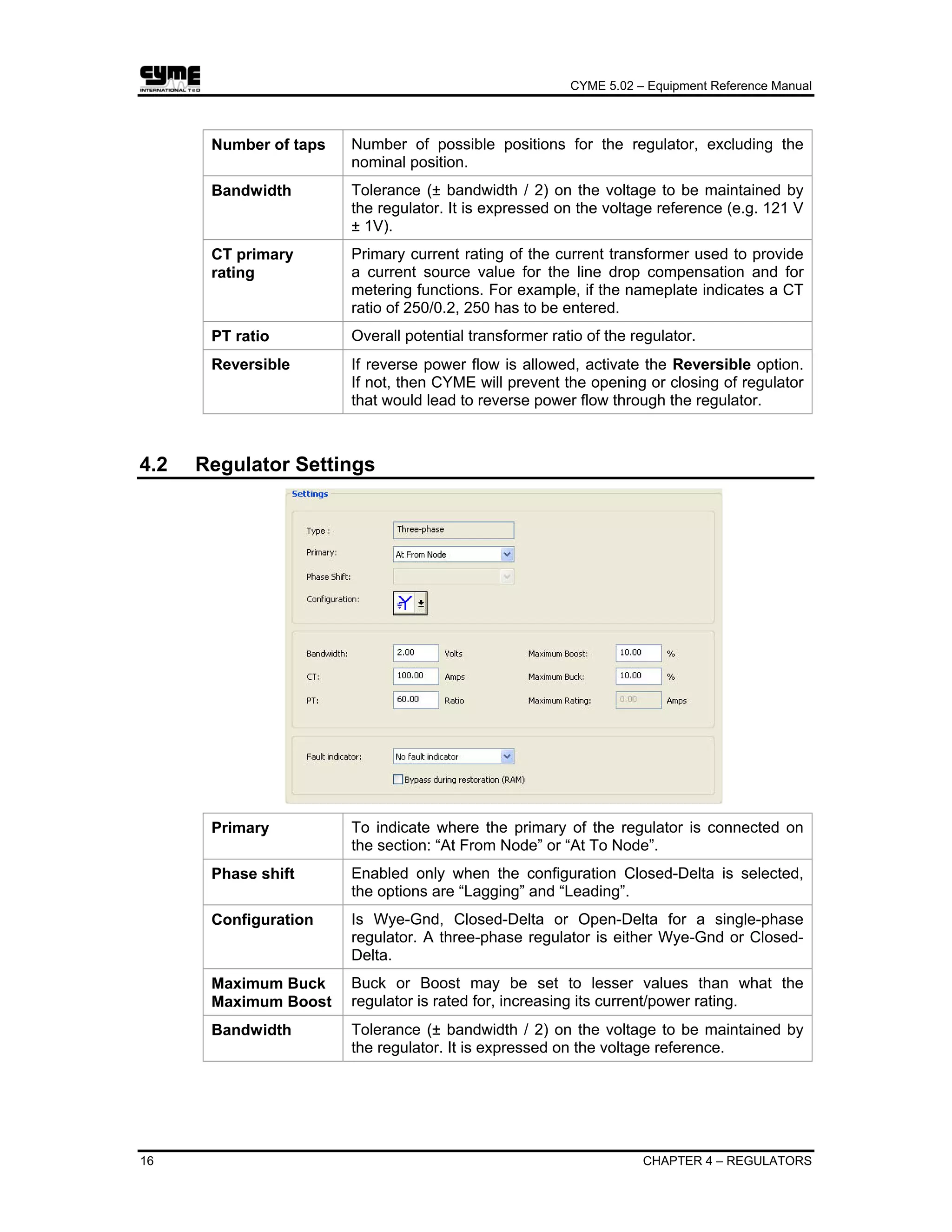
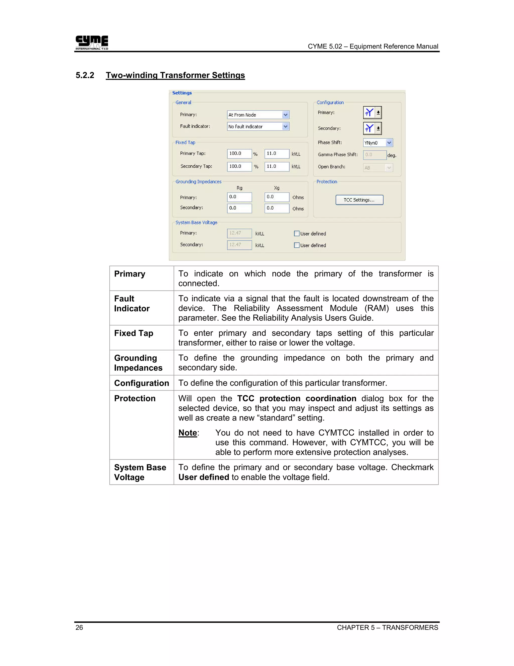
To launch the Equipment Assistant which will guide you through the process of creating a new equipment variant. Copy: To create a copy of the selected equipment. Same as Create Copy from the Equipment List menu. Delete: To delete the selected equipment from the list. Same as Delete from the Equipment List menu. Rename: To rename the selected equipment. Same as Rename from the Equipment List menu. Compare With Library: To compare the equipment data with the reference data in the equipment library. Equipment whose data have changed will have a red dot placed next to it. Equipment with exactly the same data as the reference in the library will have a check mark next to it. Update


