Downloaded 50 times


![The Sheath Voltage Limiter
Copyright 2013 ArresterWorks ArresterFacts 032 January 2013 8
ride through the fault, then station type
arresters may need to be used.
2. If the 1000 amp switching surge residual
voltage is not available, then the 1.5kA
8/20 lightning impulse residual voltage can
be used for the margin of protection
calculation.
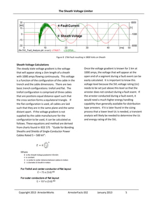
In the case study used to create Figure 14, the
switching surge voltage on the sheath without SVL
protection would rise to greater than 100kV. Per
Figure 12, this is more than 40kV above what the
jacket or interrupt insulation can withstand,
representing certain failure of the cable jacket. In
this case, with a 9.6kV Uc SVL, the voltage on the
sheath is limited to 33kV maximum.
To calculate the margin of protection during a
switching surge, it is recommended that the 1000A
switching surge residual voltage be used. Since
switching surge residual voltage is not a mandated
test for distribution type arresters, the 1000A
residual voltage may not be available. If it is not
available, a reasonable substitute for the switching
surge voltage is the 8x20 residual voltage at 1.5kA.
For the 9.6kV SVL used in the above study, the
V1000 = 1000A 30/75us residual voltage is 28.4kV.
From Figure 12, we can see that the BIL withstand
level of the jacket for a 345kV line is 60kV. This
means the switching surge margin of protection
(MP2) for this case is: MP2 = ( [( BIL x .83 ) / V1000
]-1) x 100 = 75%
Protecting the Jacket from Lightning Surge
When lightning strikes the overhead line before
the transition pole, the surge is clamped by the
arrester that is universally mounted at that
location. Most of the surge current is diverted to
earth at this pole; however, a surge voltage of
significant magnitude can travel into the cable with
a moderate level of current also entering the
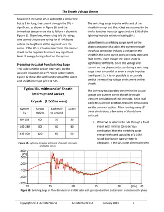
cable. Figure 15 shows the voltage and current
entering a 345kV cable with a 100kA strike a few
spans away.
Calculating margin of protection (MP1) for
lightning is very similar to what is done for
switching surges. In this case, 10kA is used for the
coordinating current and the full BIL is used for the
withstand of the jacket and interrupt insulation.
Using the same SVL as above for the switching
surge calculation, the residual voltage at 10kA is
35kV and cable BIL is 60kV, therefore: MP1 = ( [
BIL / V1000 ]-1) x 100 = 71% Again, a 9.6kV Uc
SVL provides adequate insulation protection for
the cable jacket.
Figure 14: Switching surge voltage
inducted on to Sheath of a 345kV
Cable with and without SVL
protection.
3pu switching surge on phase
conductor.
Green w/o SVL and Red with SVL.
Figure 15: Shows the voltage and current on the phase conductor of a 345kV cable with a 100kA surge to the phase a few
spans away from the transition pole](https://image.slidesharecdn.com/thesheathvoltagelimiter-161114041916/85/The-sheath-voltage_limiter-8-320.jpg)


This document discusses sheath voltage limiters (SVLs), which are surge arresters used to protect the outer jacket of underground high voltage cables. SVLs limit the voltage stress across the cable jacket during transient overvoltage events like faults, switching surges and lightning strikes to prevent puncture and moisture ingress. The document provides guidelines for selecting the proper rating for SVLs, including calculating the voltage that could appear on the cable sheath during faults based on cable characteristics, and ensuring the SVL's voltage rating is above this level so it does not conduct during faults. It also discusses using simulations and margins of protection to determine if the SVL can adequately protect the cable jacket from other transient overvoltages.


