Download as PDF, PPTX
![33
Hans Kr. Høidalen, NTNU-Norway
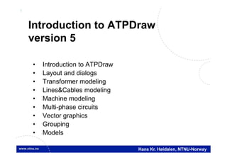
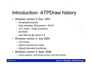
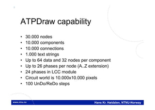
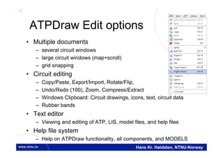
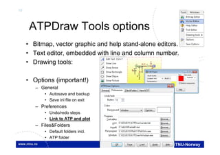
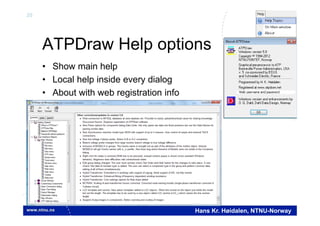
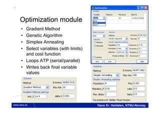
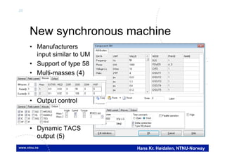
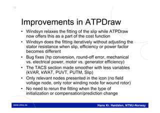
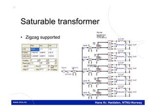
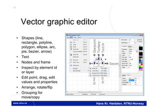
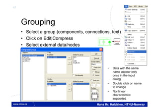
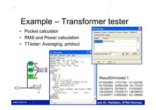
Example
• Create double-cage IM model
• Tuning of weight factors required to get rated current.
Torque
IM
WI
0.0 0.5 1.0 1.5 2.0
Omega [pu]
-3.0
-2.0
-1.0
0.0
1.0
2.0
3.0 Torque [pu]](https://image.slidesharecdn.com/atp-draw-tutorial-161114042751/85/Atp-draw-tutorial-33-320.jpg)
![38
Hans Kr. Høidalen, NTNU-Norway
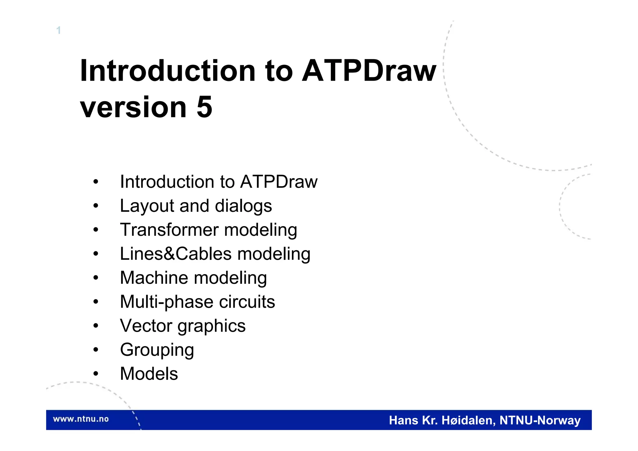
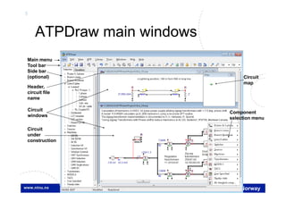
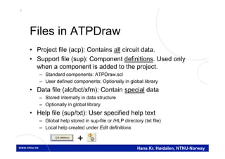
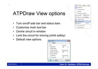
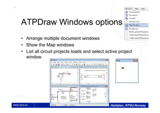
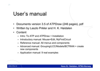
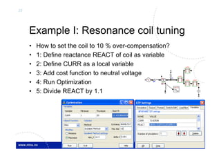
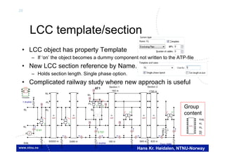
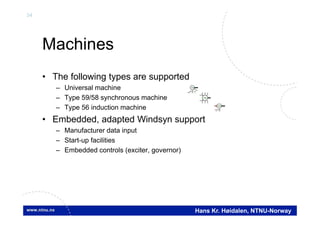
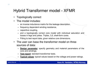
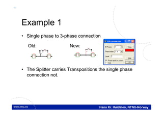
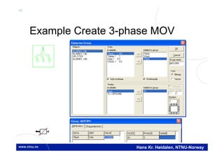
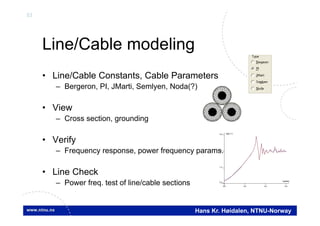
BCTRAN
• Automatic inclusion of external magnetization characteristic
BCT
Y
16 kV
I
VVXFMR
Y
I
V
V
V
XFMR
BCTRAN
(f ile Exa_16.pl4; x-v ar t) c:X0004A-LV_XA c:X0004A-LV_BA
0.00 0.02 0.04 0.06 0.08 0.10[s]
-70
-40
-10
20
50
80
[A]](https://image.slidesharecdn.com/atp-draw-tutorial-161114042751/85/Atp-draw-tutorial-38-320.jpg)
![42
Hans Kr. Høidalen, NTNU-Norway
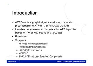
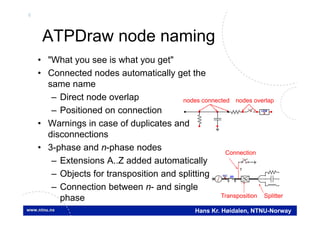
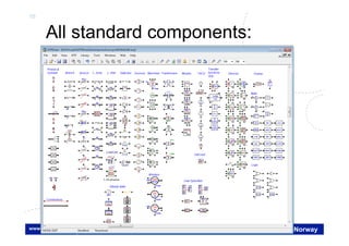
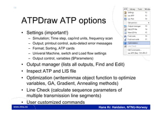
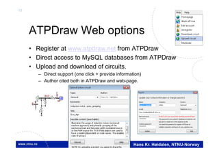
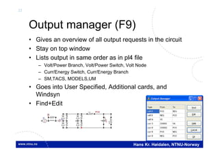
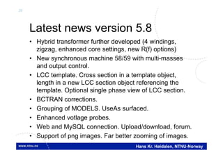
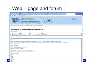
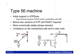
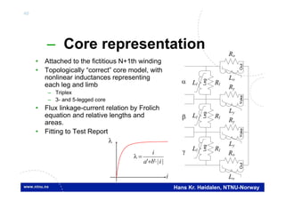
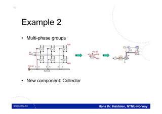
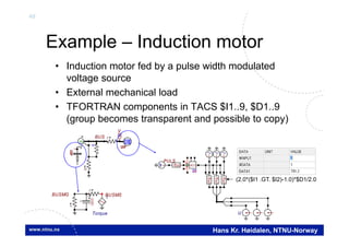
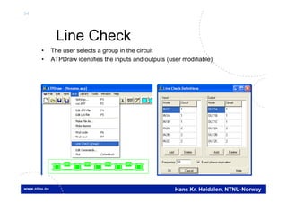
Latest news, Version 5.0 available from October 2006
Sponsored by BPA & EEUG
• Vector graphics
– Improved zoom
– Larger, dynamic icon; RLC, transformer,
switch…
– Individual selection area
• Multi-phase nodes
– 1..26 phases, A..Z extension
– MODELS input/output X[1..26]
– Connection between n-phase and single phase
– 21 phases in LCC components
• New file management
– Project file follows the PKZIP 2 format.
Improved compression. acp-extension.
– Sup-file only used when a component is
created.
– External data moved from files to memory.
– Individual, editable help strings for all
components.
LCC LCC LCC LCC
1
132 kV
132/11.3
SAT
Y
22.2 mH
MODEL
fourier
M
I
1
AC
POS
NEG
PULSE 1 4 3 6 5 2
6-phase](https://image.slidesharecdn.com/atp-draw-tutorial-161114042751/85/Atp-draw-tutorial-42-320.jpg)
![51
Hans Kr. Høidalen, NTNU-Norway
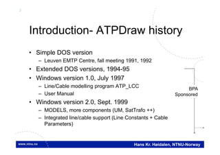
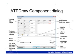
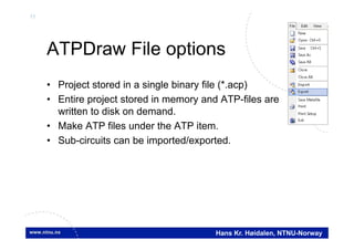
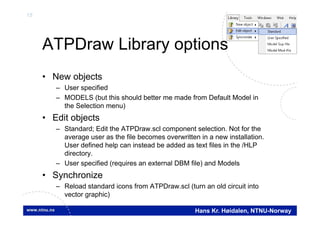
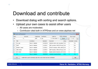
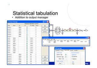
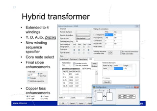
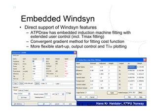
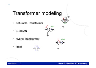
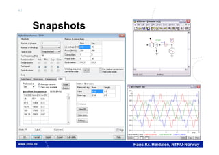
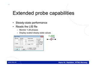
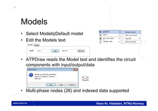
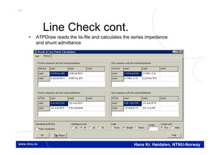
Example
• Multi-phase Models
• New Model probe
SAT
Y
Z
132 kV
SAT
Y Y
5 uH
VCable
132/11.3
SAT
Y Y
SAT
Y
Z
SAT
Y Y
HVBUS
I
5 uH
0.0265
UI
5 mF
U(0)
+
22.2 mH
VCable 0.0265
UI
5 mF
U(0)
+
MODEL
fourier
M
1
Regulation
11.3/10.6 kV
transformers
Diode
bridgesZig-zag
transformers
ZN0d11y0
10.7/0.693 kV
MODEL FOURIER
INPUT X --input signal to be transformed
DATA FREQ {DFLT:50} --power frequency
n {DFLT:26} --number of harmonics to calculate
OUTPUT absF[1..26], angF[1..26],F0 --DFT signals
VAR absF[1..26], angF[1..26],F0,reF[1..26], imF[1..26],
i,NSAMPL,OMEGA,D,F1,F2,F3,F4
(f ile Exa_14.pl4; x-v ar t) m:X0027E m:X0027G m:X0027V m:X0027Y
0.02 0.03 0.04 0.05 0.06 0.07 0.08 0.09 0.10[s]
0
4
8
12
16
20](https://image.slidesharecdn.com/atp-draw-tutorial-161114042751/85/Atp-draw-tutorial-51-320.jpg)

ATPDraw is a graphical preprocessor for ATP that allows modeling of power system components using a drag-and-drop interface. It supports over 100 standard components and handles node naming automatically based on connections. The document discusses ATPDraw's history, file handling, modeling capabilities including transformers, machines and transmission lines, and additional features such as output management, optimization, and integration with an online database.


![[CLASS 2014] Palestra Técnica - Jason Larsen](https://cdn.slidesharecdn.com/ss_thumbnails/ptclass30-jasonlarsen-141113071044-conversion-gate01-thumbnail.jpg?width=640&height=640&fit=bounds)


