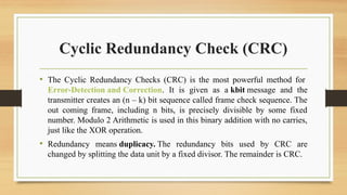
Cyclic Redundancy Check(CRC)
• The Cyclic Redundancy Checks (CRC) is the most powerful method for
Error-Detection and Correction. It is given as a kbit message and the
transmitter creates an (n – k) bit sequence called frame check sequence. The
out coming frame, including n bits, is precisely divisible by some fixed
number. Modulo 2 Arithmetic is used in this binary addition with no carries,
just like the XOR operation.
• Redundancy means duplicacy. The redundancy bits used by CRC are
changed by splitting the data unit by a fixed divisor. The remainder is CRC.
3.
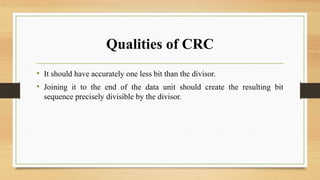
Qualities of CRC
•It should have accurately one less bit than the divisor.
• Joining it to the end of the data unit should create the resulting bit
sequence precisely divisible by the divisor.
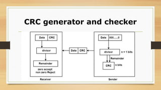
Process
• A stringof n 0s is added to the data unit. The number n is one smaller than
the number of bits in the fixed divisor.
• The new data unit is divided by a divisor utilizing a procedure known as
binary division; the remainder appearing from the division is CRC.
• The CRC of n bits interpreted in phase 2 restores the added 0s at the end
of the data unit.
6.
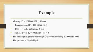
Example
• Message D= 1010001101 (10 bits)
• Predetermined P = 110101 (6 bits)
• FCS R = to be calculated 5 bits
• Hence, n = 15 K = 10 and (n – k) = 5
• The message is generated through 25
: accommodating 1010001101000
• The product is divided by P.
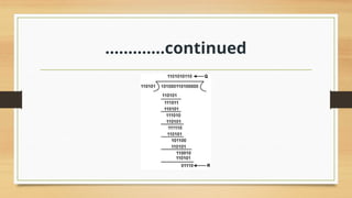
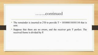
…….continued
• The remainderis inserted to 25
D to provide T = 101000110101110 that is
sent.
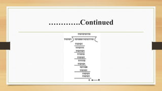
• Suppose that there are no errors, and the receiver gets T perfect. The
received frame is divided by P.
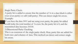
Single Parity Check:
Aparity bit is added to ensure that the number of 1s in a data block is either
even (even parity) or odd (odd parity). This can detect single-bit errors.
Example:
If you have the data 1011 and are using even parity, the parity bit added
would make the total number of 1s even. So, the parity bit is 0, and the
transmitted data becomes 10110.
2-Dimensional Parity Checking:
This is an extension of the single parity check. Here, parity bits are added for
both rows and columns of data. This method can detect and correct single-
bit errors.
12.
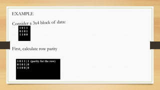
EXAMPLE
1 0 11
0 1 0 1
1 1 0 0
Consider a 3x4 block of data:
1 0 1 1 | 1 (parity for the row)
0 1 0 1 | 0
1 1 0 0 | 0
First, calculate row parity
13.
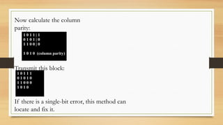
1 0 11 | 1
0 1 0 1 | 0
1 1 0 0 | 0
1 0 1 0 (column parity)
Now calculate the column
parity:
Transmit this block:
1 0 1 1 1
0 1 0 1 0
1 1 0 0 0
1 0 1 0
If there is a single-bit error, this method can
locate and fix it.


![[DSC Europe 25] Slobodan Dolinic - Smart and Intelligent Green Region.pptx](https://cdn.slidesharecdn.com/ss_thumbnails/0bribinjsp6ghwtvsvor-2-sigre-slobodan-dolinic-260115093812-c9c10e90-thumbnail.jpg?width=640&height=640&fit=bounds)

![[DSC Europe 25] Elena Menshikova - AI-Powered Operational Excellence: Revolut...](https://cdn.slidesharecdn.com/ss_thumbnails/es6nholbqy3zaao2c2yd-2-elena-menshikova-data-ai-in-decision-making-260115093812-4fba8b38-thumbnail.jpg?width=640&height=640&fit=bounds)


