
Recommended
More Related Content
What's hot
What's hot (20)
Similar to Ohm's law
Similar to Ohm's law (20)
Recently uploaded
Recently uploaded (20)
Ohm's law
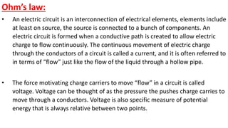
- 1. Ohm’s law: • An electric circuit is an interconnection of electrical elements, elements include at least on source, the source is connected to a bunch of components. An electric circuit is formed when a conductive path is created to allow electric charge to flow continuously. The continuous movement of electric charge through the conductors of a circuit is called a current, and it is often referred to in terms of “flow” just like the flow of the liquid through a hollow pipe. • The force motivating charge carriers to move “flow” in a circuit is called voltage. Voltage can be thought of as the pressure the pushes charge carries to move through a conductors. Voltage is also specific measure of potential energy that is always relative between two points.
- 2. • The term voltage describes how much force or how much potential energy is required to move a charge carrier form one particular point in a circuit to another particular point. This potential energy is caused by a difference in charge. When current is flowing in a circuit this potential or pressure must be kept by some kind of pump to move the electric charges. This pump cab be a battery or generator. • The flow of charge through any material encounter an opposing force similar in many respects to mechanical friction. This opposition is due to the collisions of the current- carrying charged particles with fixed particles (electrons and atoms) than make up the structure of the material, which converts electrical energy into another form of energy such as heat, is called resistance.
- 3. • Ohm’s law describes the relationship between the three fundamentals electric quantities, current, voltage, and resistance. Ohm’s law states that the current 𝐼 flowing in a circuit is directly proportional to the applied voltage 𝑉 and inversely proportional to the resistance 𝑅, provided the temperature remains constant. Thus, 𝐼 = 𝑉 𝑅 (amperes, A) 𝑒𝑞 1
- 4. • Equation (1) is known as Ohm’s law in honor of George Simon Ohm. The law clearly reveals that for a fixed resistance, the greater the voltage across the resistor, the more the current will flow through this resistor, and the more the resistance for the same voltage, the less the current. In other words, the current is proportional to the applied voltage and inversely proportional to the resistance.
- 5. • Alternate statement of Ohm’s law is the voltage or potential difference (V) across a resistor equal to the product of current flowing in the resistance (𝐼) and the resistance (R), 𝑉 = 𝐼𝑅(volts, 𝑉) 𝑒𝑞 2 • By mathematical manipulations, the resistance (R) can be found in terms of the other two quantities: 𝑅 = 𝑉 𝐼 𝑜ℎ𝑚𝑠, Ω 𝑒𝑞 3
- 6. So that 1Ω = 1 𝑉/𝐴 • An element with 1 ohm resistance allows a current flow of 1 amp when there exists a potential of 1 volt across the element. In another words, when there exists an electric potential of 1 volt across a conductor with a resistance of 1 ohm, then 1 ampere of electric current will flow through the conductor.
- 7. • The three quantities of Eqs. (1) through (3) are defined by the simple circuit of Fig. 1. The current 𝐼 of Eq. (1) results from applying a voltage supply of 𝑉 across a network having a resistance 𝑅. Equation (2) determine the voltage 𝑉 required to establish a current 𝐼 through a network having a resistance 𝑅. Equation (3) determine the resistance of a network 𝑅 that results in a current 𝐼 due to the voltage 𝑉. FIG. 1 Basic circuit
- 8. • To apply Ohm’s law, we must pay carful attention to the current direction and voltage polarity. The direction of the current 𝐼 and the voltage 𝑉 must confirm with the passive sign convention, as shown in Fig. (2). • So if we have two electrical devices, one with current 𝐼1 flowing from plus to minus 𝑉1, then we have 𝑉1 = 𝐼1𝑅. If you consider the other device, 𝐼2 flowing from minus to plus 𝑉2, then we have 𝑉2 = −𝐼2𝑅. So the voltage sign you get to first you can use that one for your calculation. For 𝑉1, the current gets to the plus sign first, so it is positive current. When calculating 𝑉2, the current gets to the minus sign first, so it is negative current. FIG. 2 Defining polarities
- 9. • When solving a problem, we have to use the passive sign convention in order to be able to assign the polarities across a voltage drop of the elements. • In problem 1, we have a voltage drop across the resistor R that is unknown as far as the polarity goes. So we first assign a direction for the current. And then, knowing the direction for the current that we have assigned, then we can assign the polarity across the resistor R. FIG. 3-a For problem 1
- 10. • In the passive sign convention, the current is assumed to enter the positive side of the voltage polarity across the element. So, if we assign the current to go in clockwise direction around this single loop circuit, then the voltage drop across the resistor R as shown in the figure. • If we want to calculate the amount of current flows in this single circuit, we use the first formula of Ohm’s law: 𝐼 = 𝑉 𝑅 = 110 2200 = 0.05 𝐴 FIG. 3-b Assigning the polarity across R
- 11. Note that • we have used the capital letters for the current and the voltage to indicate the 𝐼 and 𝑉 are time-invariant quantities, except in cases where the quantity especially voltage and current is described in terms of a brief period of time called instantons value. For example, the voltage of a battery which is stable over a long period of time will be symbolized with the capital letter 𝑉, while the voltage peak of a lighting strike at every instant hits a power line would be most likely be symbolized with a lowercase letter 𝑣 to designate that value as being at a single moment time. This rule is true for the current as well.
- 12. • Since the value of R can range from zero to infinity, it is important that we consider the two extreme values of R. An element with R=0 is called a short circuit, as shown in Fig. 4(a). For a short circuit, 𝑉 = 𝐼𝑅= 0 𝑒𝑞 4 Showing that the voltage is zero but the current could have any Value. So, we can say that a short circuit is a circuit element with resistance approaching zero. FIG. 4 (a) Short circuit (R=0), (b) Open circuit (R=∞)
- 13. • Similarly, an element with R=∞ is known as open circuit, as shown in Fig. 4(b). For an open circuit, 𝐼 = lim 𝑅=∞ 𝑉 𝑅 = 0 𝑒𝑞 5 Showing that the current is zero but the voltage could have any value. So, we can say that an open circuit is a circuit element with resistance approaching infinity.
- 14. Ohm’s law and Power: • There is another series of equations related to Ohm’s law because of the fact that the electric power 𝑃 in watts [the rate that energy is supplied by a source or dissipated by a device] in any electrical circuit is equal to the current in amperes multiplied by the voltage in volts. Thus: 𝑃 = 𝑉𝐼 𝑒𝑞 6 Where 𝑃: power in watts 𝐼: current in amps 𝑉: voltage in volts
- 15. Eq (6) may be transported to find either 𝐼 or 𝑉 𝐼 = 𝑃 𝑉 𝑒𝑞 7 𝑎𝑛𝑑 𝑉 = 𝑃 𝐼 𝑒𝑞 8 Since 𝑅 = 𝑉 𝐼 and 𝑉 = 𝑃 𝐼 , we have: 𝑅 = 𝑉 𝐼 = 𝑃 𝐼 𝐼 = 𝑃 𝐼 × 𝐼 = 𝑃 𝐼2
- 16. The previous formula may be transported to find either 𝐼 or 𝑃 𝐼2 = 𝑃 𝑅 𝐼 = 𝑃 𝑅 𝑒𝑞 9 𝑎𝑛𝑑 𝑃 = 𝐼2 𝑅 𝑒𝑞 10 Since 𝑃 = 𝑉𝐼 and 𝐼 = 𝑉 𝑅 , we have: 𝑃 = 𝑉𝐼 = 𝑉 𝑉 𝑅 = 𝑉2 𝑅 𝑒𝑞 11
- 17. The previous formula may be transported to find either 𝑉 or 𝑅 𝑃 = 𝑉2 𝑅 , 𝑉2 = 𝑃 × 𝑅 𝑉 = 𝑃 𝑅 𝑒𝑞 12 𝑎𝑛𝑑 𝑅 = 𝑉2 𝑃 𝑒𝑞 13
- 18. Ohm’s law formula wheel: Below is a formula wheel for Ohm's Law relationships between P, I, V, and R. It is just a representation of the algebraic manipulation of the previous equations. To use the wheel, choose the variable to solve for in the middle of the wheel, then use the relationship for the two known variables within the cross section of the circle.
- 19. Linear and Nonlinear Devices: • Figure 5.1 shows a circuit in which current 𝐼 can be varied by the variable resistor 𝑅2. For different values of 𝑅2, the current flowing in resistor 𝑅1, displayed on the ammeter, and the p.d across 𝑅1, displayed on the voltameter are plotted on the graph 5-2(a) where the straight line graph passing through the origin indicates that there are linear relationship between the current and the voltage. In other words, the current 𝐼 passes through the resistor 𝑅1 is directly proportional to the voltage (p.d) across the resistor 𝑅1. Since the slope (voltage/current) is constant, resistance 𝑅1 is constant, so 𝑅1 can be considered as an example of a linear device or ohmic device, which mean that this device follow Ohm’s law. FIG. 5-1 Circuit in which current can be varied
- 20. • If the resistor 𝑅1 is replaced by a component such as filament lamp, and recording the voltage and the current across the lamp, and we plot those data points, what we find is the relationship that look like that in the graph 5-2(b). We see that this line will have a curve to it, it will no have a constant slope. Since the slope changes, the filament lamp is an example of a nonlinear device or nonohmic device, which mean that this device does not follow Ohm’s law. FIG. 5-2: Graphs of p.d vs. current (a) Liner device (b) Nonlinear device