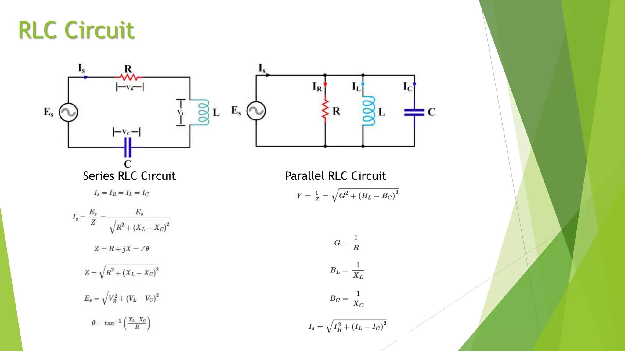
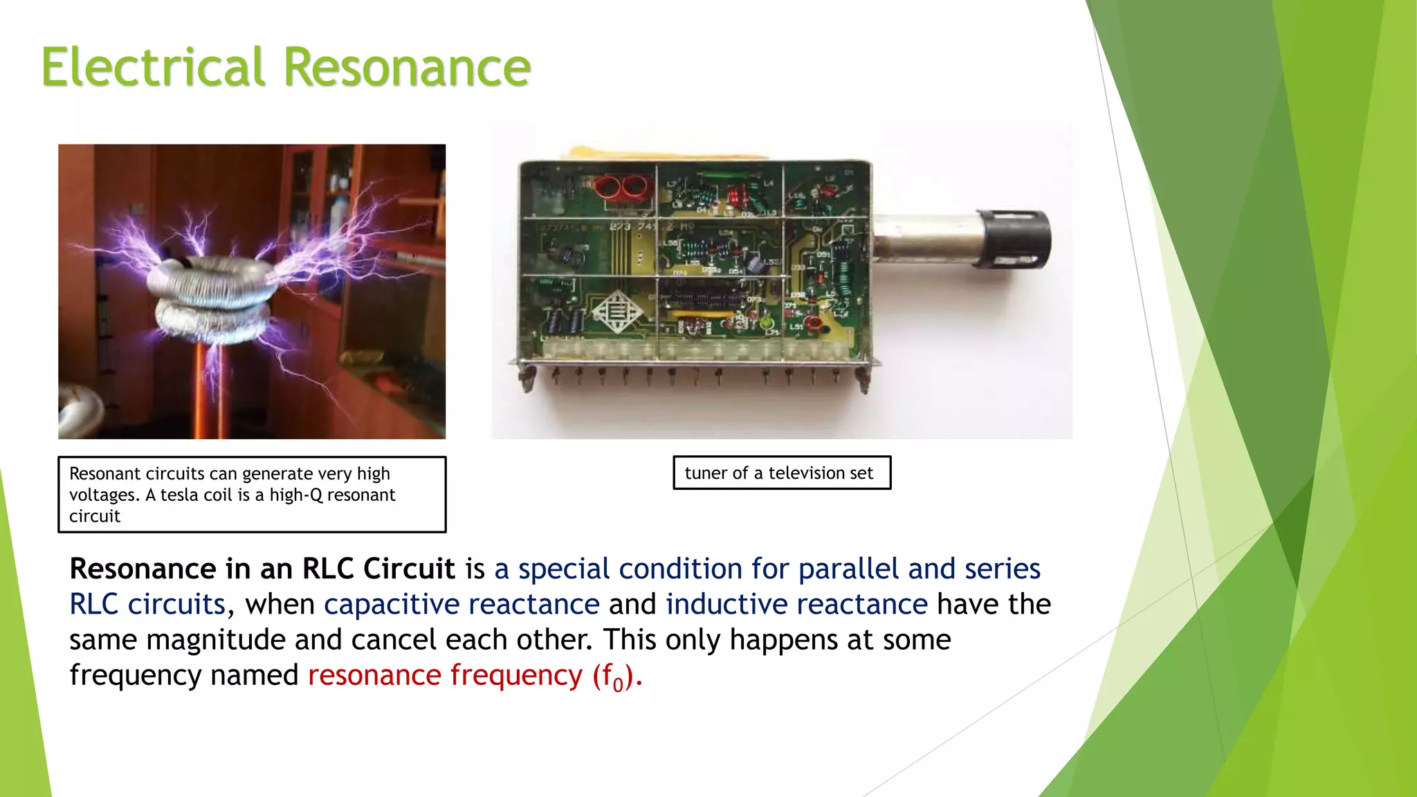
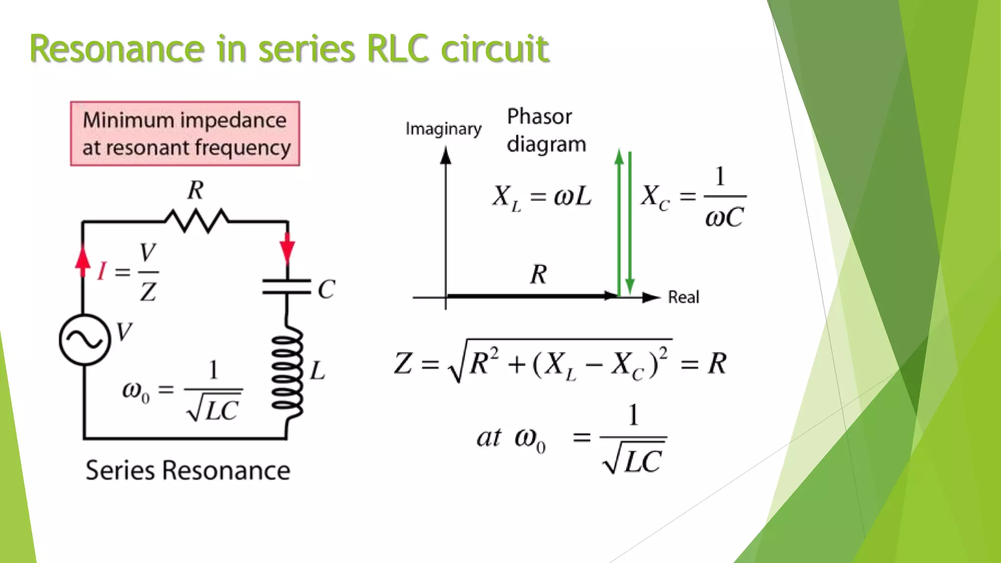
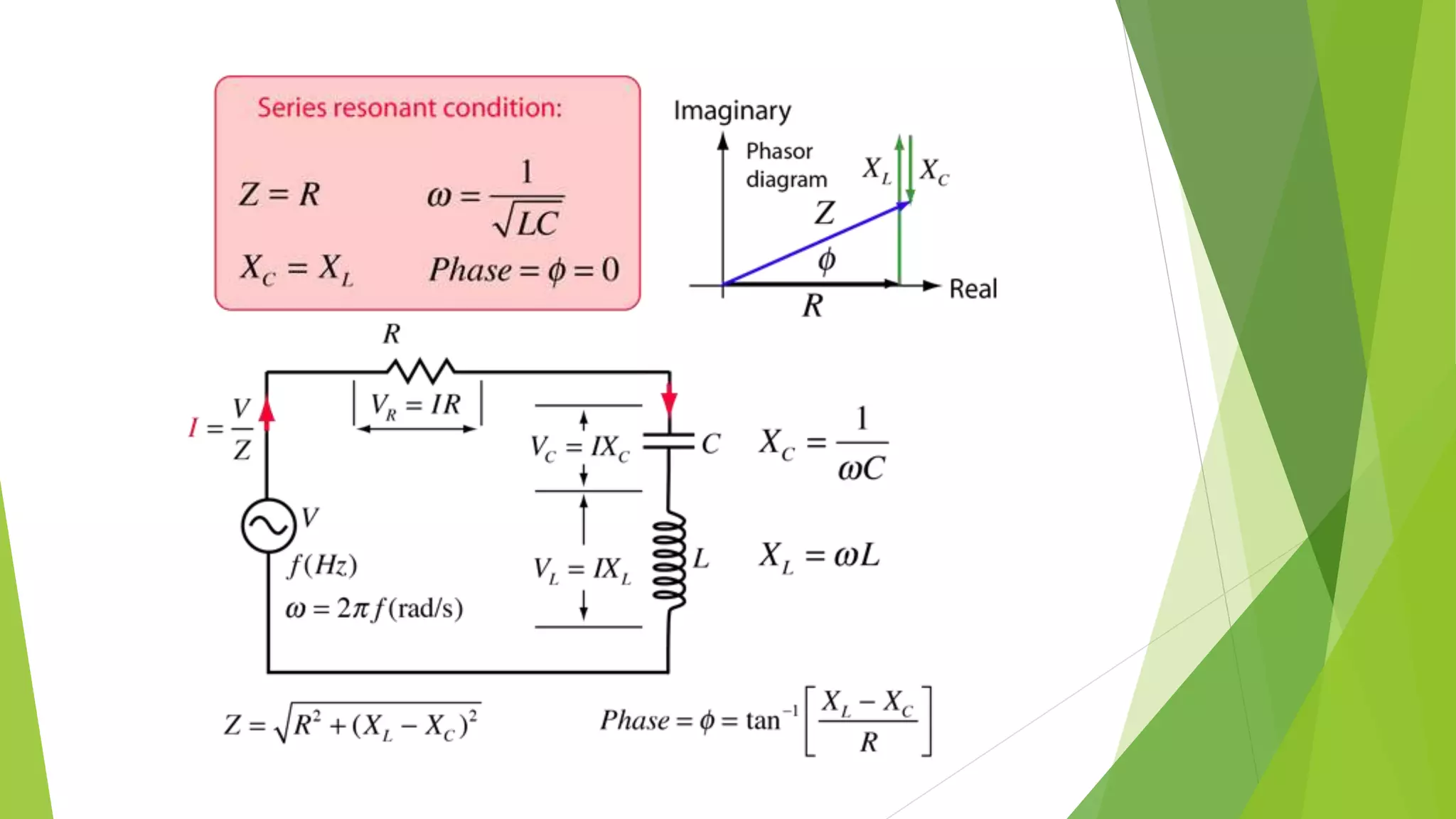
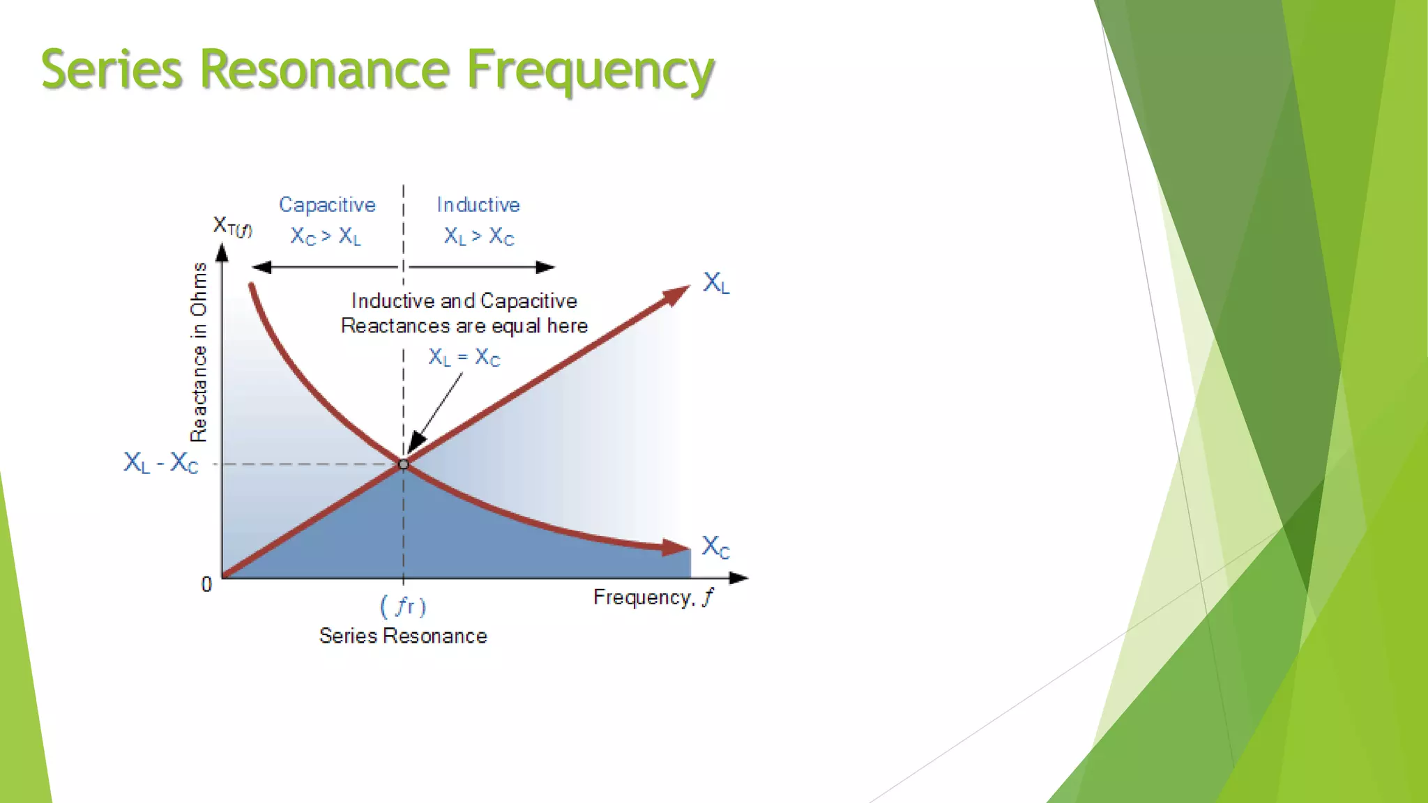
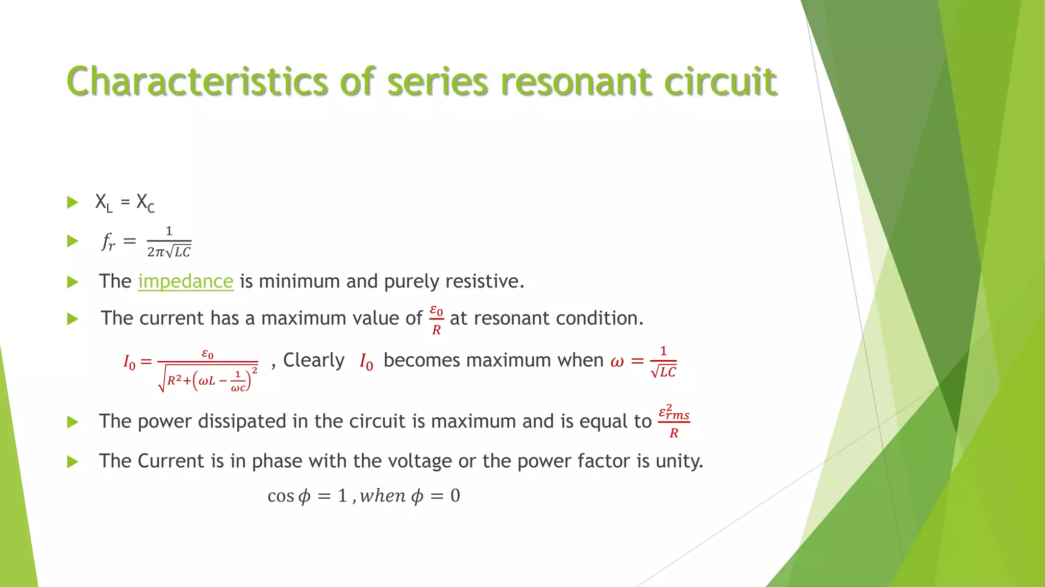
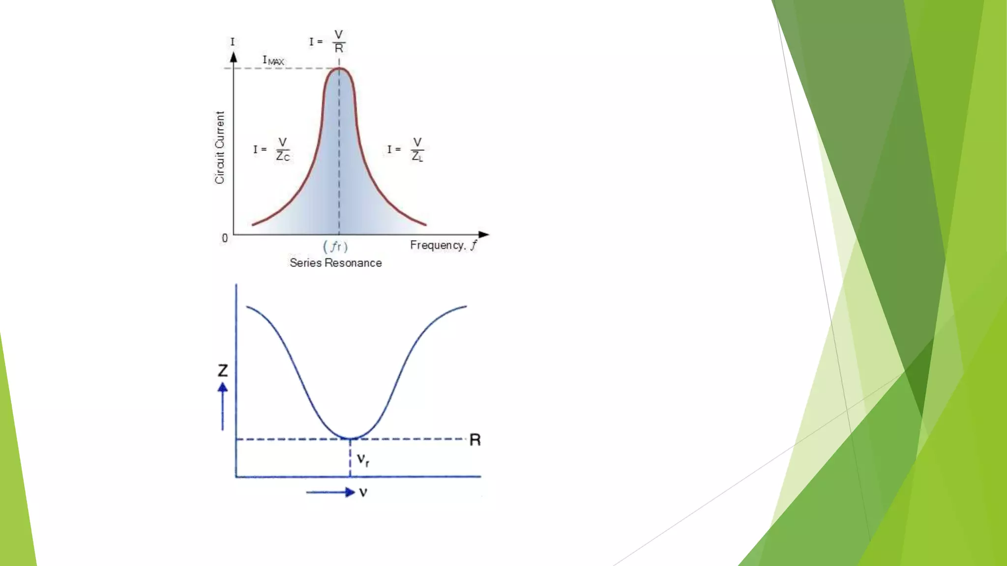
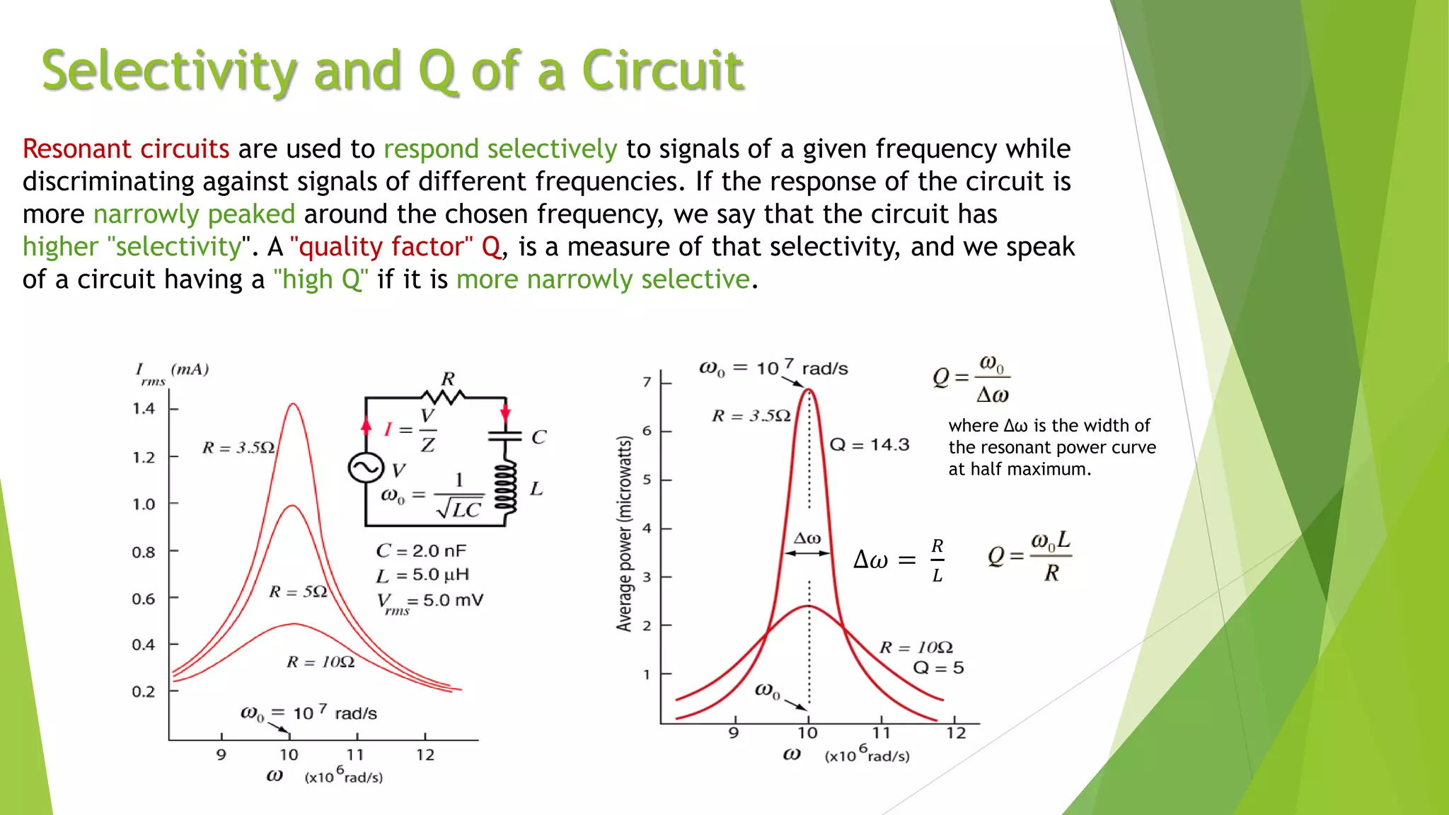
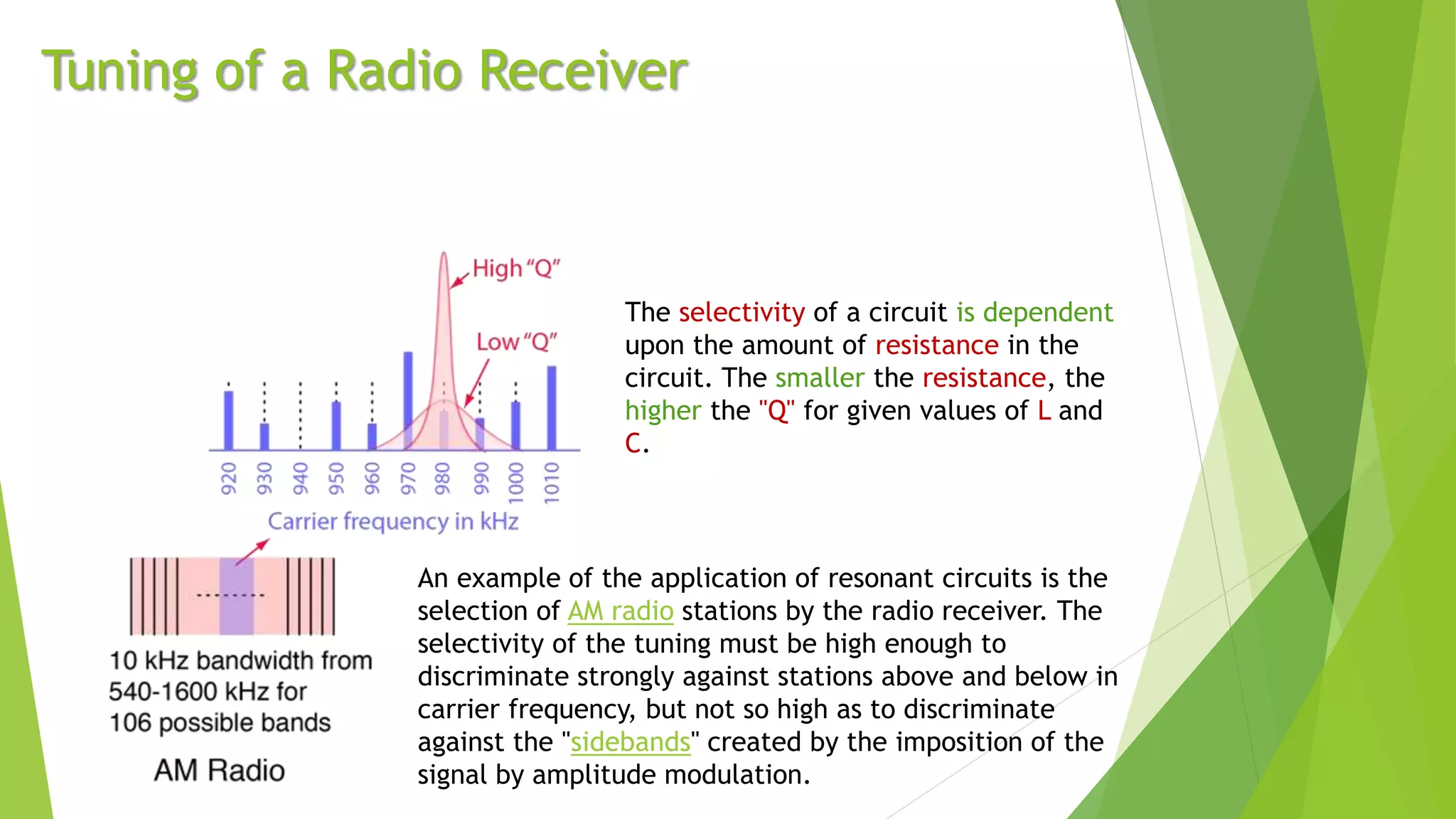
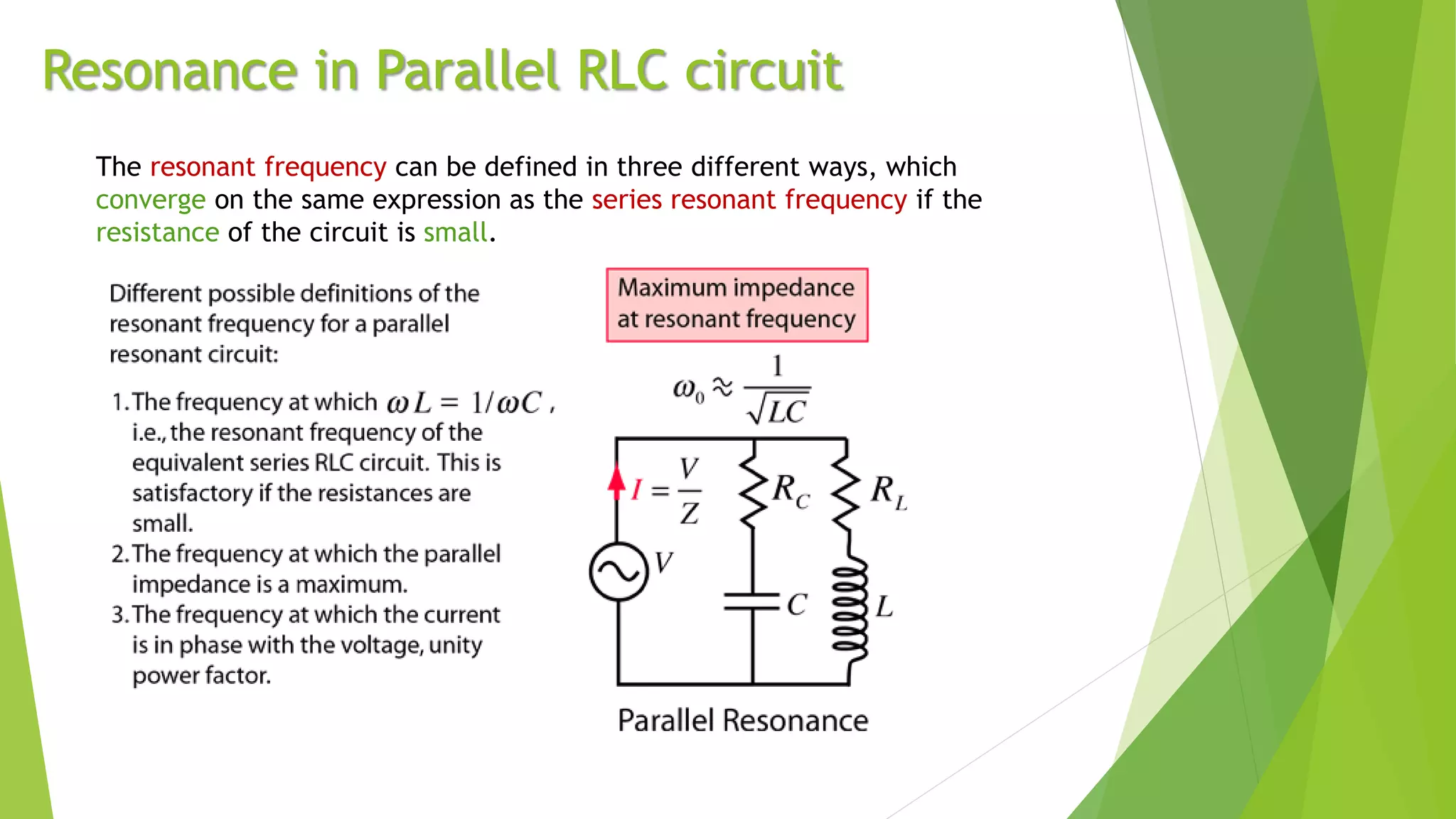
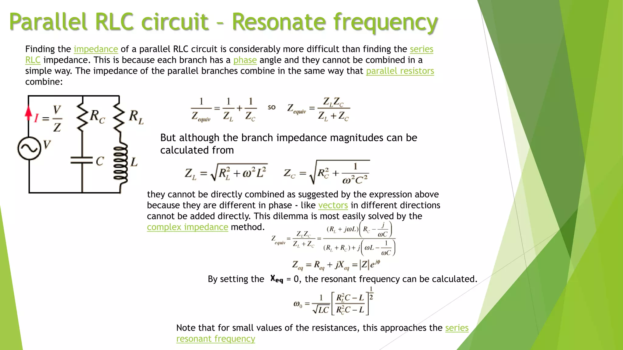
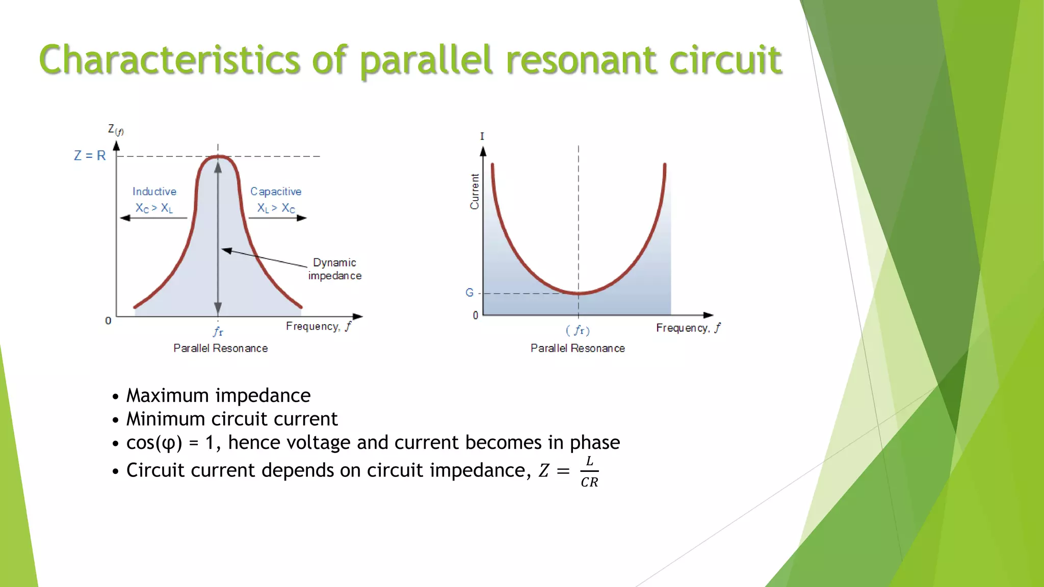
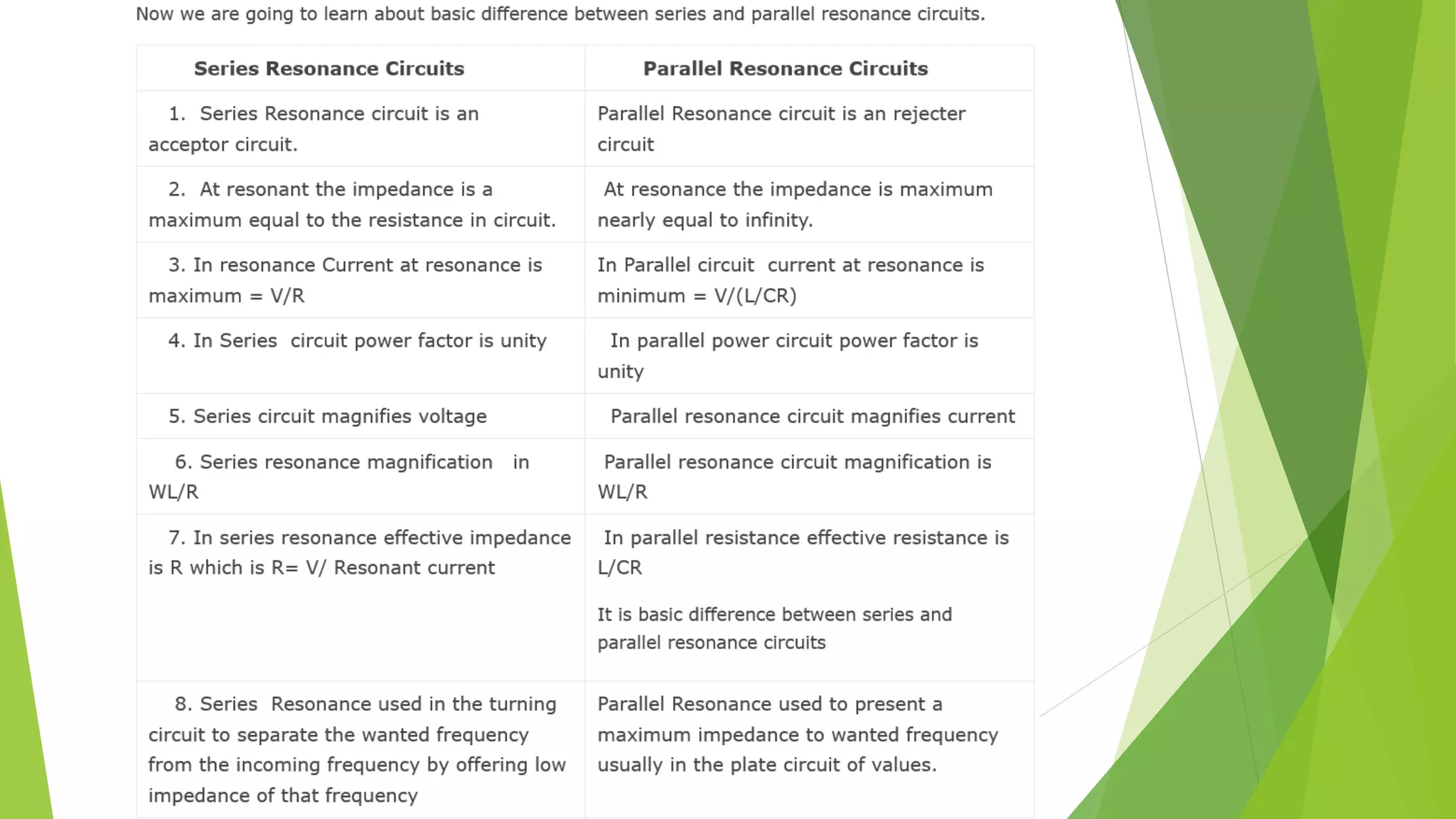
Resonance
Presentation by Rishab
Series RLC Circuit Parallel RLC Circuit
RLC Circuit
Resonance in an RLC Circuit is a special condition for parallel and series
RLC circuits, when capacitive reactance and inductive reactance have the
same magnitude and cancel each other. This only happens at some
frequency named resonance frequency (f0).
Electrical Resonance
Resonant circuits can generate very high
voltages. A tesla coil is a high-Q resonant
circuit
tuner of a television set
Resonance in series RLC circuit
Series Resonance Frequency
Characteristics of series resonant circuit
 XL = XC
 𝑓𝑟 =
1
2𝜋 𝐿𝐶
 The impedance is minimum and purely resistive.
 The current has a maximum value of
𝜀0
𝑅
at resonant condition.
𝐼0 =
𝜀0
𝑅2+ 𝜔𝐿 −
1
𝜔𝑐
2
, Clearly 𝐼0 becomes maximum when 𝜔 =
1
𝐿𝐶
 The power dissipated in the circuit is maximum and is equal to
𝜀𝑟𝑚𝑠
2
𝑅
 The Current is in phase with the voltage or the power factor is unity.
cos 𝜙 = 1 , 𝑤ℎ𝑒𝑛 𝜙 = 0
Selectivity and Q of a Circuit
Resonant circuits are used to respond selectively to signals of a given frequency while
discriminating against signals of different frequencies. If the response of the circuit is
more narrowly peaked around the chosen frequency, we say that the circuit has
higher "selectivity". A "quality factor" Q, is a measure of that selectivity, and we speak
of a circuit having a "high Q" if it is more narrowly selective.
Δ𝜔 =
𝑅
𝐿
where Δω is the width of
the resonant power curve
at half maximum.
Expression for Quality Factor - Q
Tuning of a Radio Receiver
An example of the application of resonant circuits is the
selection of AM radio stations by the radio receiver. The
selectivity of the tuning must be high enough to
discriminate strongly against stations above and below in
carrier frequency, but not so high as to discriminate
against the "sidebands" created by the imposition of the
signal by amplitude modulation.
The selectivity of a circuit is dependent
upon the amount of resistance in the
circuit. The smaller the resistance, the
higher the "Q" for given values of L and
C.
Resonance in Parallel RLC circuit
The resonant frequency can be defined in three different ways, which
converge on the same expression as the series resonant frequency if the
resistance of the circuit is small.
Parallel RLC circuit – Resonate frequency
Finding the impedance of a parallel RLC circuit is considerably more difficult than finding the series
RLC impedance. This is because each branch has a phase angle and they cannot be combined in a
simple way. The impedance of the parallel branches combine in the same way that parallel resistors
combine:
But although the branch impedance magnitudes can be
calculated from
they cannot be directly combined as suggested by the expression above
because they are different in phase - like vectors in different directions
cannot be added directly. This dilemma is most easily solved by the
complex impedance method.
By setting the = 0, the resonant frequency can be calculated.
Note that for small values of the resistances, this approaches the series
resonant frequency
Characteristics of parallel resonant circuit
• Maximum impedance
• Minimum circuit current
• cos(φ) = 1, hence voltage and current becomes in phase
• Circuit current depends on circuit impedance, 𝑍 =
𝐿
𝐶𝑅
References
 Halliday Resnick, Jearl Walker 9th edition, International Student Version,
Chapter 31 Electromagnetic Oscillations and Alternating current.
 New Simplified Physics by S.L. Arora
 hyperphysics.phy-astr.gsu.edu
 electronics-tutorials.ws
 rfwireless-world.com
 kullabs.com
 electrical4u.com
 theelectricalportal.com

Resonance.pptx

  • 1.
  • 2.
    Series RLC CircuitParallel RLC Circuit RLC Circuit
  • 3.
    Resonance in anRLC Circuit is a special condition for parallel and series RLC circuits, when capacitive reactance and inductive reactance have the same magnitude and cancel each other. This only happens at some frequency named resonance frequency (f0). Electrical Resonance Resonant circuits can generate very high voltages. A tesla coil is a high-Q resonant circuit tuner of a television set
  • 4.
  • 6.
  • 7.
    Characteristics of seriesresonant circuit  XL = XC  𝑓𝑟 = 1 2𝜋 𝐿𝐶  The impedance is minimum and purely resistive.  The current has a maximum value of 𝜀0 𝑅 at resonant condition. 𝐼0 = 𝜀0 𝑅2+ 𝜔𝐿 − 1 𝜔𝑐 2 , Clearly 𝐼0 becomes maximum when 𝜔 = 1 𝐿𝐶  The power dissipated in the circuit is maximum and is equal to 𝜀𝑟𝑚𝑠 2 𝑅  The Current is in phase with the voltage or the power factor is unity. cos 𝜙 = 1 , 𝑤ℎ𝑒𝑛 𝜙 = 0
  • 9.
    Selectivity and Qof a Circuit Resonant circuits are used to respond selectively to signals of a given frequency while discriminating against signals of different frequencies. If the response of the circuit is more narrowly peaked around the chosen frequency, we say that the circuit has higher "selectivity". A "quality factor" Q, is a measure of that selectivity, and we speak of a circuit having a "high Q" if it is more narrowly selective. Δ𝜔 = 𝑅 𝐿 where Δω is the width of the resonant power curve at half maximum.
  • 10.
  • 11.
    Tuning of aRadio Receiver An example of the application of resonant circuits is the selection of AM radio stations by the radio receiver. The selectivity of the tuning must be high enough to discriminate strongly against stations above and below in carrier frequency, but not so high as to discriminate against the "sidebands" created by the imposition of the signal by amplitude modulation. The selectivity of a circuit is dependent upon the amount of resistance in the circuit. The smaller the resistance, the higher the "Q" for given values of L and C.
  • 12.
    Resonance in ParallelRLC circuit The resonant frequency can be defined in three different ways, which converge on the same expression as the series resonant frequency if the resistance of the circuit is small.
  • 13.
    Parallel RLC circuit– Resonate frequency Finding the impedance of a parallel RLC circuit is considerably more difficult than finding the series RLC impedance. This is because each branch has a phase angle and they cannot be combined in a simple way. The impedance of the parallel branches combine in the same way that parallel resistors combine: But although the branch impedance magnitudes can be calculated from they cannot be directly combined as suggested by the expression above because they are different in phase - like vectors in different directions cannot be added directly. This dilemma is most easily solved by the complex impedance method. By setting the = 0, the resonant frequency can be calculated. Note that for small values of the resistances, this approaches the series resonant frequency
  • 14.
    Characteristics of parallelresonant circuit • Maximum impedance • Minimum circuit current • cos(φ) = 1, hence voltage and current becomes in phase • Circuit current depends on circuit impedance, 𝑍 = 𝐿 𝐶𝑅
  • 16.
    References  Halliday Resnick,Jearl Walker 9th edition, International Student Version, Chapter 31 Electromagnetic Oscillations and Alternating current.  New Simplified Physics by S.L. Arora  hyperphysics.phy-astr.gsu.edu  electronics-tutorials.ws  rfwireless-world.com  kullabs.com  electrical4u.com  theelectricalportal.com

Editor's Notes

  • #4 Resonant circuits can generate very high voltages. A tesla coil is a high-Q resonant circuit tuner of a television set.