This document provides information on simulating and analyzing farfield data from antennas in CST Studio Suite. It discusses defining broadband and single frequency farfield monitors and probes, optimizing farfield results, extracting co-polarization and cross-polarization data, calculating the phase center, exporting data to GRASP, simulating circularly polarized antennas, and combining simulation results. Checklists are provided for ensuring accurate farfield simulation results.
![www.cst.com
33
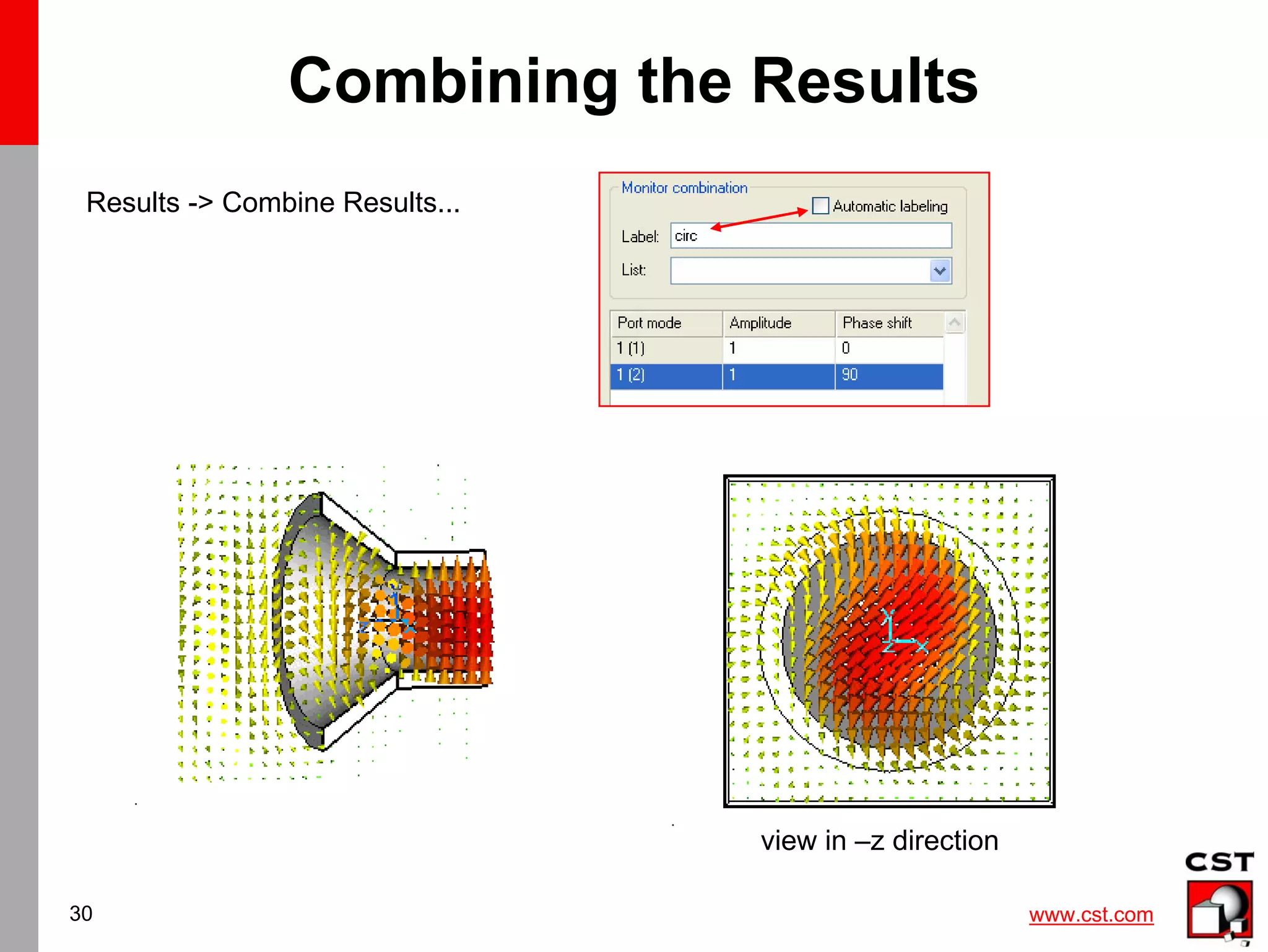
Result Template for Combined Monitor
1[1.0,0.0]+2[1.0,90],[80]
Note: In all farfield result templates
the Excitation string has
to be set manually !!
It is recommended to use
a shorter userdefined labelling
instead of the automatic
number- labelling.
„circ“
„circ“](https://image.slidesharecdn.com/cstantenna-cststudiosuite2006b-220819212101-362d1cc6/75/CST_ANTENNA-CST-STUDIO-SUITE-2006B-pdf-33-2048.jpg)
![www.cst.com
34
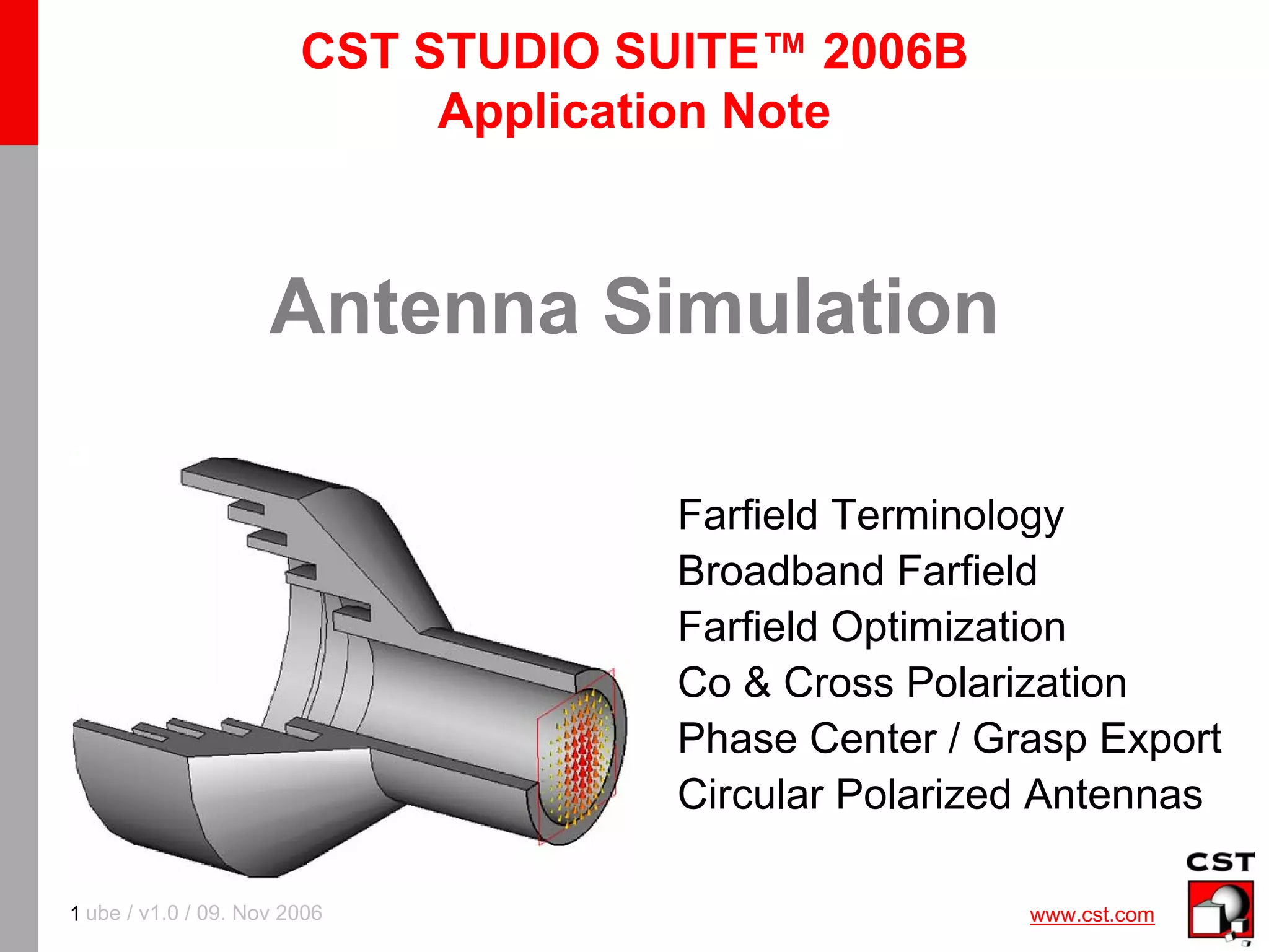
Summary
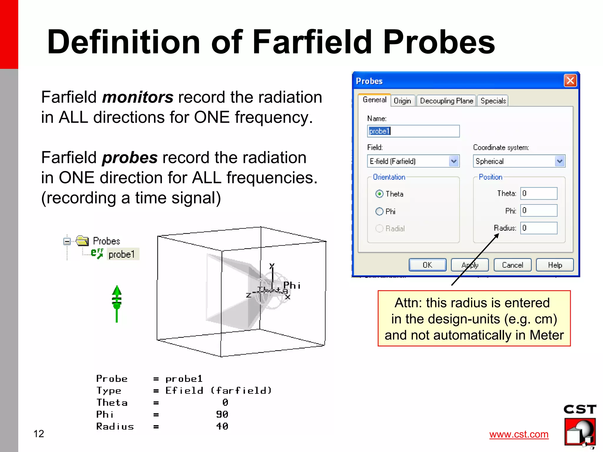
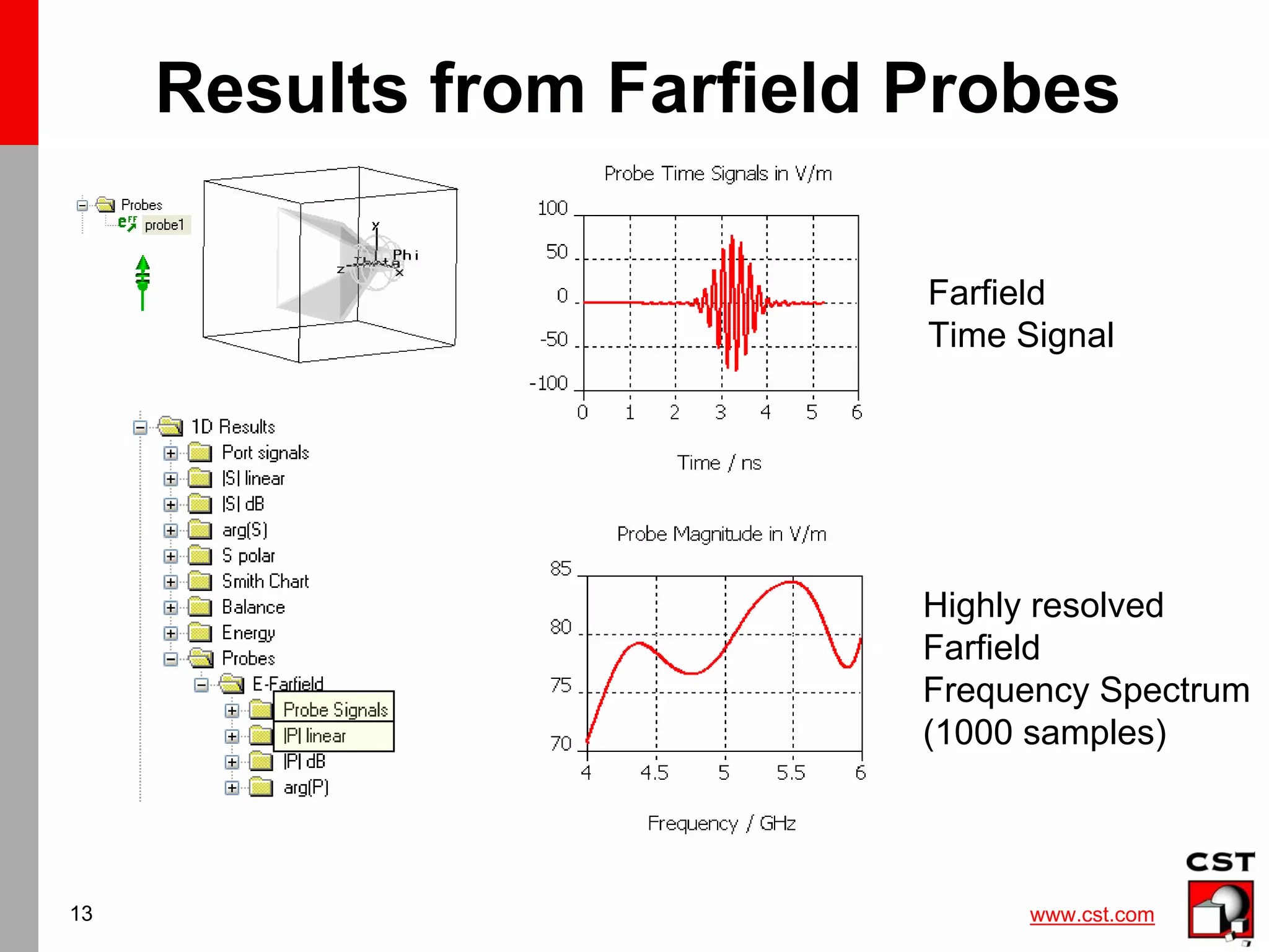
• Antenna Farfield can be recorded in time and
frequency domain (Probe / Monitor)
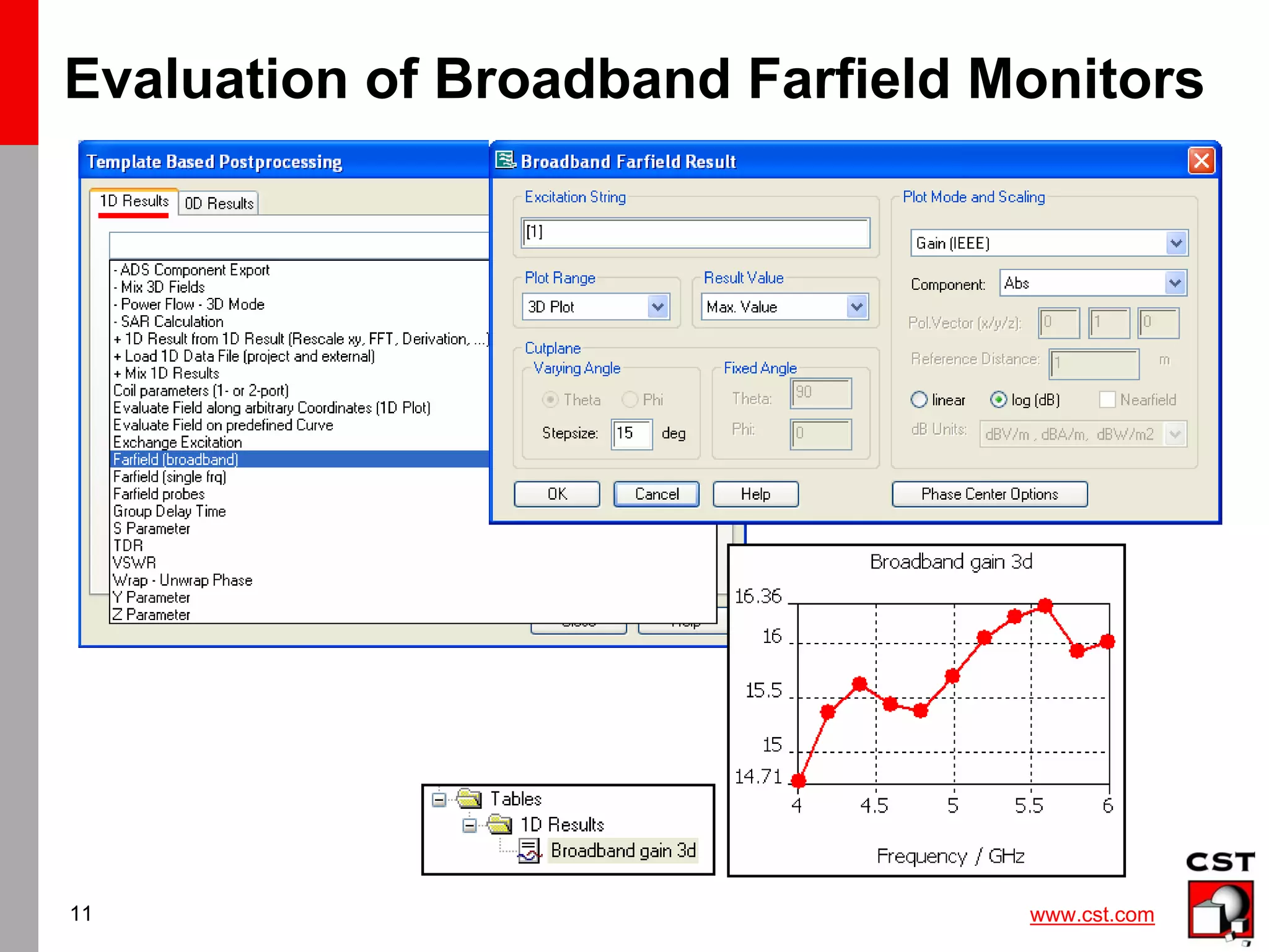
• Postprocessing templates automize result
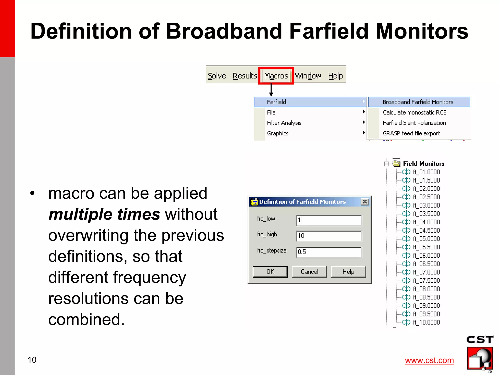
extraction (e.g. broadband farfield)
• checklist for accurate farfield:
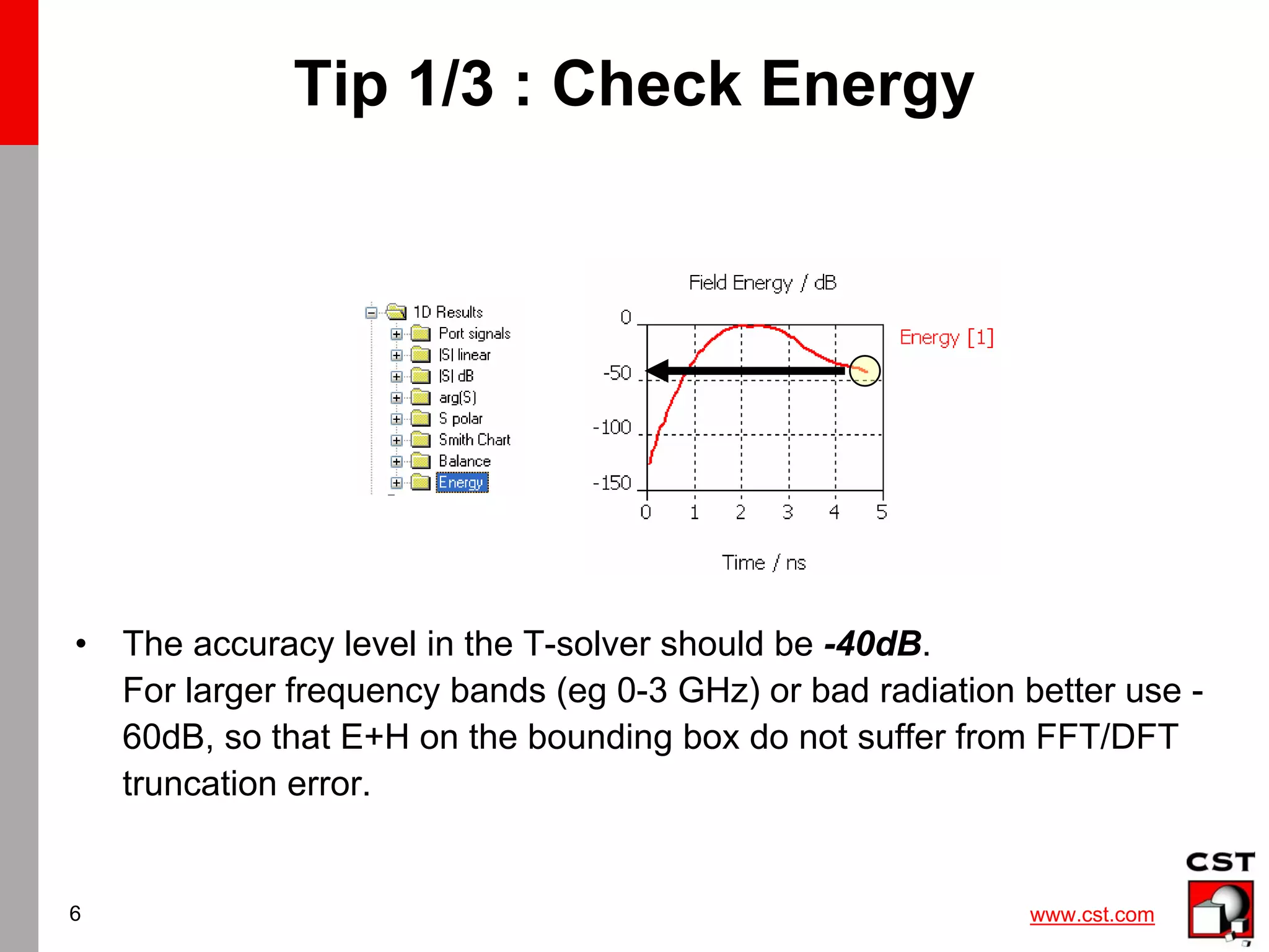
– energy decayed to -40dB [-60dB] ?
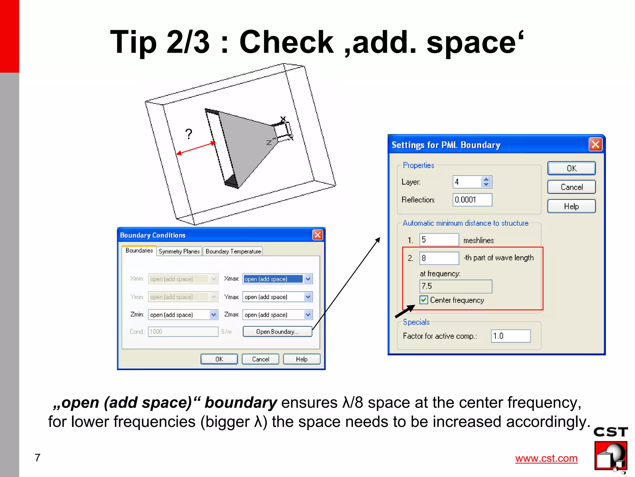
– enough surrounding space (λ/8) – open (add space)?
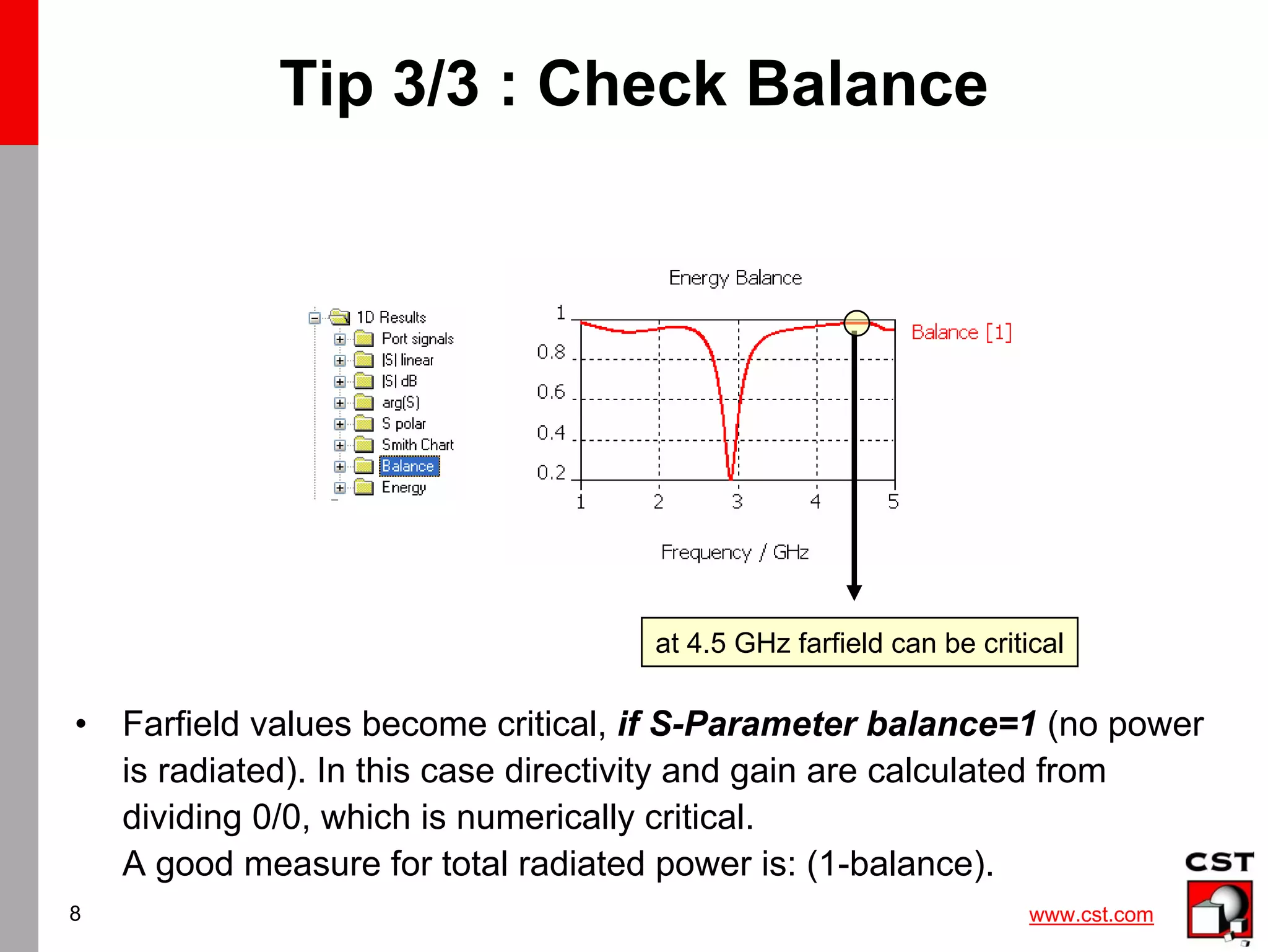
– Is antenna radiating at this frequency? (S-balance<1 ?)
• Advanced capabilities to extract:
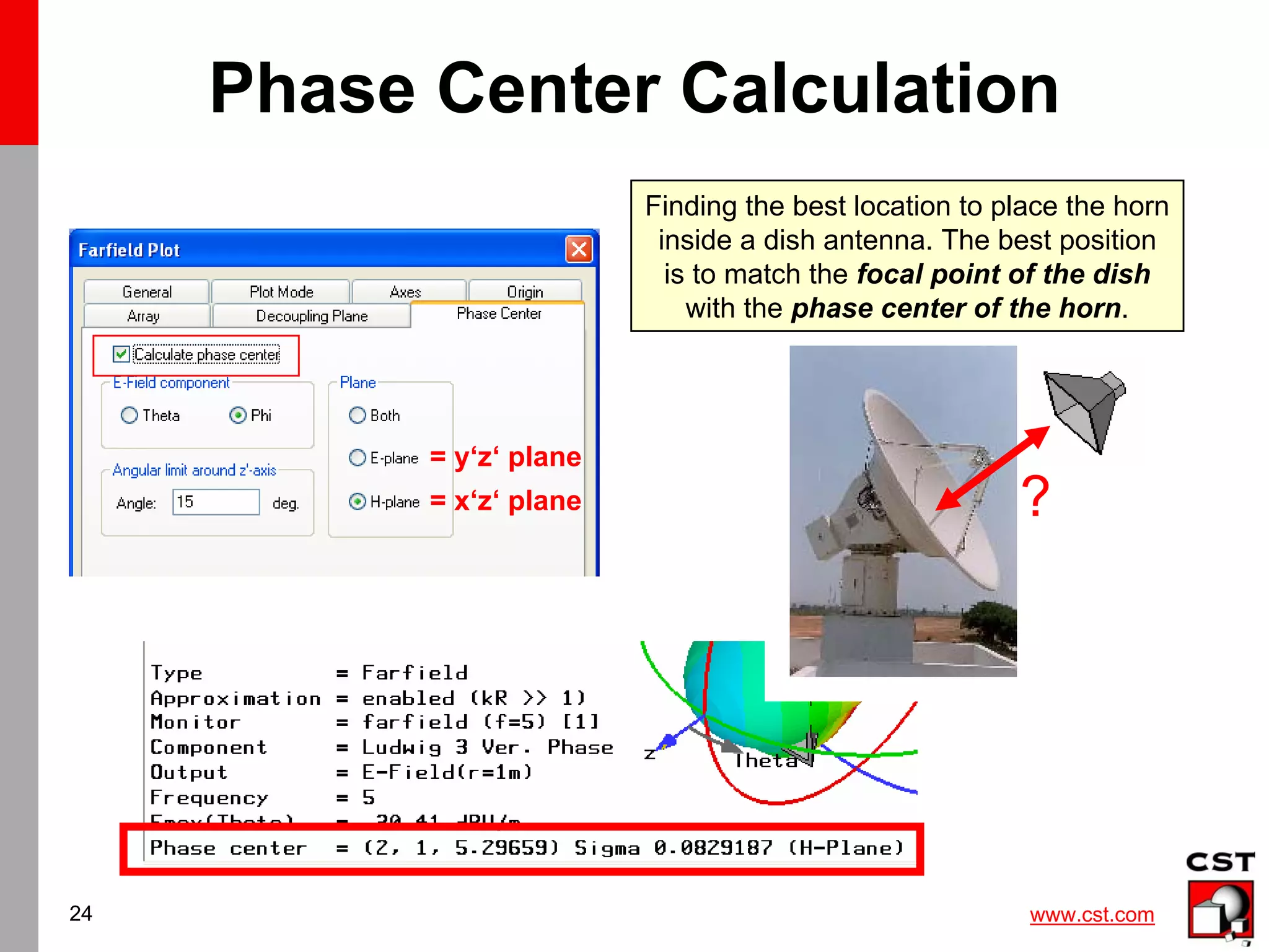
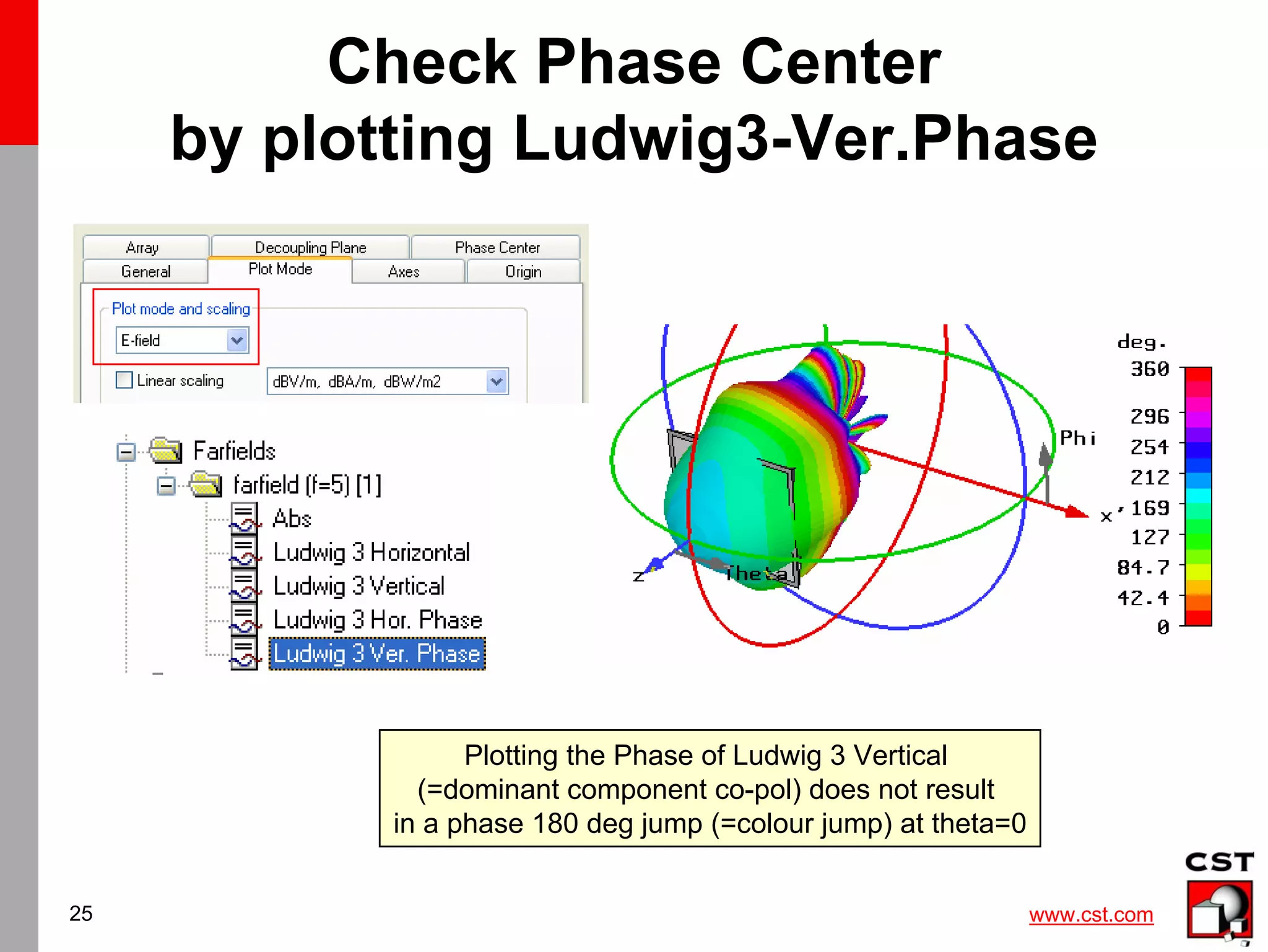
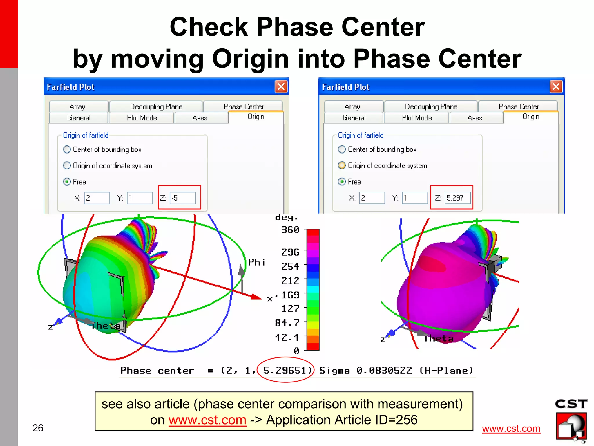
co+cross-pol / phase center / Grasp input data
RL pol / axial ratio](https://image.slidesharecdn.com/cstantenna-cststudiosuite2006b-220819212101-362d1cc6/75/CST_ANTENNA-CST-STUDIO-SUITE-2006B-pdf-34-2048.jpg)


![3_Antenna Array [Modlue 4] (1).pdf](https://cdn.slidesharecdn.com/ss_thumbnails/3antennaarraymodlue41-220419112111-thumbnail.jpg?width=640&height=640&fit=bounds)