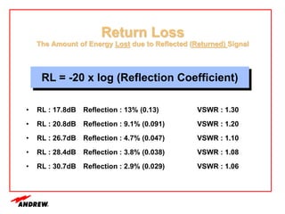
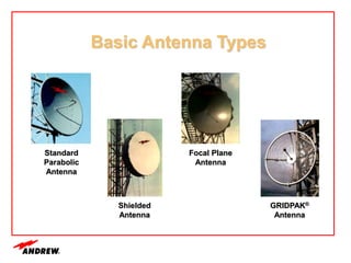
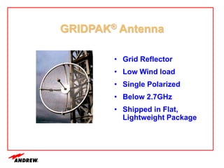
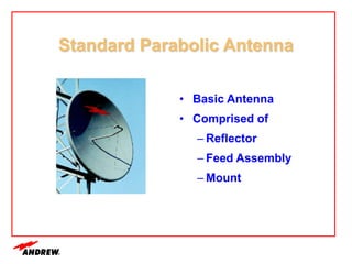
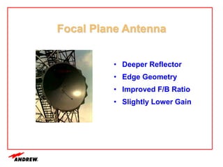
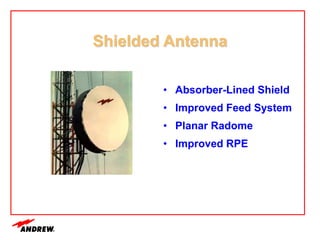
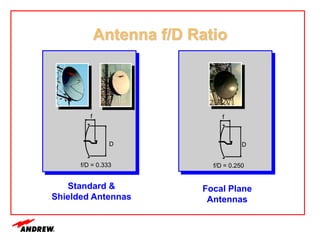
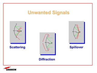
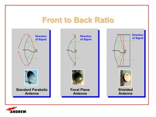
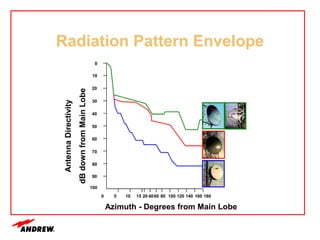
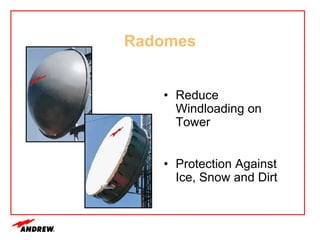
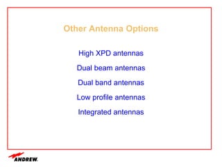
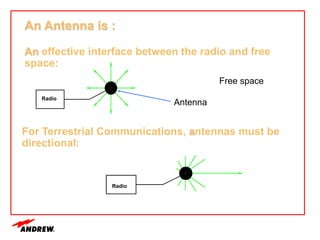
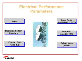
Terrestrial microwave antennas are used for point-to-point communication between two locations and require line of sight. Different types of antennas exist depending on location, usage, and frequency, and their key electrical performance parameters include gain, front-to-back ratio, radiation pattern, return loss, and interport isolation. Common types discussed are parabolic, shielded, GRIDPAK, and focal plane antennas.


![Ga (dBi) = 10 log10 h [ 4 p Aa / l2 ]
Where:
Ga = Antenna Directive Gain (Catalog spec)
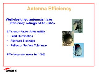
h = Aperture Efficiency (50-55%)
Aa = Antenna Aperture Area
l = Wavelength (speed of light / frequency)
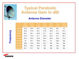
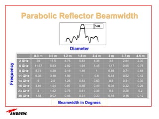
Parabolic Antenna
Directive Gain](https://image.slidesharecdn.com/unit2-230214105609-e0879a92/85/UNIT-2-ppt-5-320.jpg)