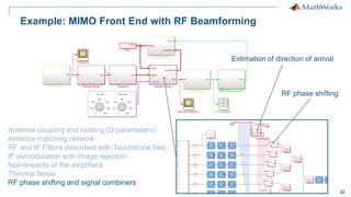
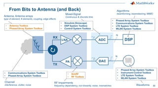
1
© 2016 The MathWorks, Inc.
Modeling & Simulating Antenna Arrays and
RF Beamforming Algorithms
Giorgia Zucchelli – Product Marketing MathWorks
giorgia.zucchelli@mathworks.nl
2
Agenda
 Introducing antenna design in MATLAB using full wave EM simulation
– Designing and analyzing custom antennas and antenna arrays
– Improving antenna design workflow efficiency through speed up and optimization methods
– Including edge and coupling effects for more realistic antenna array modeling
 Modelling the architecture of RF front ends
– Developing baseband and RF beamforming algorithms
– Integrating antenna arrays into complex systems
3
What Are the Challenges with Antenna and RF Design?
 Understanding the antenna requirements
– Individual antenna parameters: frequency, directivity, geometry, material, efficiency
– What antenna or antenna array do I use? Many types, very diverse, infinite configurations
– Electromagnetic solvers: correct analysis set up
 Exploring the RF architecture while considering different scenarios
– Evaluate the cost of off-the-shelf components: overdesign vs digital calibration and correction
– Design adaptive systems: multi-standard, multi-frequency, resilient to interferers
 Wireless system integration: does my system really work?
– How do I partition my system?
– Antenna + RF + digital signal processing + control logic
4
Introducing Antenna Design in MATLAB
Using Full Wave EM Simulation
5
Antenna Toolbox Demo
Design and analysis of one antenna element, in just 5 lines of MATLAB code
>> p = patchMicrostrip
>> p.Height = 0.01;
>> impedance(p, (500e6:10e6:2e9));
>> current(p, 1.7e9);
>> pattern(p, 1.7e9);
6
Antenna Toolbox
 Easy design
– Library of parameterized antenna elements
– Functionality for the design of antenna arrays
– No need for full CAD design
 Rapid simulation setup
– Method of Moments field solver for port, field, and surface analysis
– No need to be an EM expert
 Seamless integration
– Model the antenna together with signal processing algorithms
– Rapid iteration of different antenna scenarios for radar and
communication systems design
7
 Dipole antennas
– Dipole, Vee, Folded, Meander, Triangular bowtie, Rounded bowtie
 Monopole antennas
– Monopole, Top hat, Inverted-F, inverted-L, Helix
 Patch antennas
– Microstrip patch, PIFA
 Spirals
– Equiangular, Archimedean
 Loops
– Circular, rectangular
 Backing structures
– Reflector and cavity
 Other common antennas
– Yagi Uda, Slot, Vivaldi, Biquad, Horn
Antenna Library: Readily Available Geometries
8
What if my Antenna is not in the Library?
 Define your custom planar structure
– Define the antenna geometry using PDE Toolbox
– Define the mesh using MATLAB
delaunayTriangulation
– Use third party tools to generate a mesh structure
 Import 2D mesh with Antenna Toolbox
– Define the feeding point
– Analyse the antenna
 Integrate your custom antenna
– Add a backing structure
– Define a dielectric substrate
– Build an array with custom elements
9
What if my Antenna is Mounted on a Dielectric Substrate?
 Antenna are often mounted on substrates
 Dielectric properties:
 Dielectric properties affect resonance, bandwidth,
efficiency, pattern …
 Use the dielectric catalogue listing existing materials
 Define your own dielectric material
Dielectric Relative permittivity Loss Tangent
Air 1 0
Other >1 (typically <10) >0 (typically ~1e-3)
“metal” antenna
(ideal conductor)
Free space (isolation)
Dielectric substrate
10
Increasing the Efficiency of the Antenna Design Workflow
Modelling the dielectric substrate can slow down analysis time:
 Use antennas in free space for first-cut design
– Combine with optimization routines to rapidly find out a suitable starting point
 Use parallel computing to speed up design space exploration
Poor directivity Optimized pattern
11
Building your First Antenna Array
>> a = linearArray
>> a.Element = p;
>> a.ElementSpacing = 0.1;
>> a.NumElements = 4;
>> show(a);
>> patternElevation(a, 1.7e9,0);
12
What if I Need to Customize my Array?
 Build regular arrays where you can change the properties of
individual elements (rotation, size, tapering)
 Describe conformal (heterogeneous) arrays in terms of
element type and arbitrary position
>> arr = conformalArray;
>> d = dipole;
>> b = bowtieTriangular;
>> arr.Element = {d, b};
>> arr.ElementPosition(1,:) = [0 0 0];
>> arr.ElementPosition(2,:) = [0 0.5 0];
13
What if my Array is Really Large?
 Infinite Array Analysis
– Repeat unit cell infinitely
– Impedance and pattern become function of frequency and scan angle
– Ignore edge effects
– Captures mutual coupling
 Validate with full wave simulation on smaller arrays
Scan Impedance @10GHz
0deg Azimuth 45deg Azimuth 90deg Azimuth
Scan Impedance
0deg Azimuth
45deg Elevation
Power Pattern
14
What if I Need to Integrate my Antenna Array with Spatial
Processing Algorithms?
 You need access to the far field radiation pattern of each element of an antenna array
– The amplitude and phase of the signal of each individual element allow you to develop
spatial algorithms
 Phased Array System Toolbox provides algorithms and tools to design, simulate, and analyze
phased array signal processing systems
– Antenna array transmitters and receivers
– Beamforming
– Estimation of Direction of Arrival
15
Computing the Antenna Array Pattern for Phased Array Algorithms
 Phased Array System Toolbox computes the array pattern using the superposition of the pattern
of each individual element
– ULA, URA, UCA and conformal arrays use the same pattern for all elements
– Heterogeneous arrays have different patterns for different elements
...
% Import antenna element in Phased Array
>> myURA = phased.URA;
>> myURA.Element = dipole;
Antenna Toolbox element (isolated)
Phased Array System Toolbox antenna array
16
What if you Need to Take into Account …
 Coupling effects in between antenna elements?
 Edge effects?
Pattern multiplication of the isolated element is not sufficient!
Full wave
Isolated element
pattern superposition Comparison
17
Computing the Accurate Radiation Pattern of Antenna Arrays
 Antenna Toolbox arrays perform full wave EM analysis
– Isolated element vs embedded element vs full array
pattern(p, 10e9);
Isolated element
pattern(l, 10e9, ...
'ElementNumber',2);
Embedded element
pattern(l, 10e9);
Full wave
18
Modelling the Array Radiation Pattern in Practice
Are the antenna elements spaced far apart?
Mid
Compute the pattern for the
central and the edge (corner)
element embedded in the array
Compute the isolated
element pattern and apply
pattern superposition
What is the size of the array?
Small
Compute the pattern for
each element embedded
in the array
Heterogeneous array
Validate (when possible)
with full EM simulation
Homogenous
array
Large
Compute the pattern for the
central element with the
infinite array approach
19
Antenna Array, Impedance, and Coupling
 Adjacent structures affect the impedance of an antenna embedded with an array
– Resonant frequency
– Electrical coupling in between antenna elements
impedance(p, freq);
Isolated element
impedance(l, freq);
Active element
S=sparameters(l, freq);
Full array
20
Example: Antenna Array Design and Integration
Desired signal + interferer
Estimation of direction of arrival
Baseband
Beamforming
Modulation error rate
Control logic to determine the
beamforming angle
21
Example: Antenna Array Design and Integration
Full wave antenna array design
Antenna array model based on pattern
superposition of the isolated element
22
Example: Antenna Array Design and Integration
Antenna coupling and loading (S-parameters)
Antenna matching
Gain, IP3, NF of the RF receiver
23
Modelling the Architecture of RF Front Ends
24
RF System-Level Design
Do you need to?
 Design the architecture and define the specs of the RF components
 Integrate RF front ends with adaptive algorithms such as DPD, AGC, beamforming
 Test and debug the implementation of the transceiver before going in the lab
 Provide a model of the RF transceiver to your colleagues and customers
25
You Need RF System Simulators
 RF and analog behavioral models with sufficient expressivity
 Ability to integrate control, calibration and signal processing algorithms
 Fast simulation of baseband + RF systems
Radio Frequency
Signals
Small simulation
time-step
Long Simulation
Runs
~10psec
~5GHz
26
Trade Off Simulation Speed and Modeling Fidelity
Deal with RF complexity with:
 Models at high levels of abstraction
 Solvers that use larger time-step
Modeling fidelity
Simulation
speed
True
Pass-Band
Circuit
Envelope
Equivalent
Baseband
Carrier
Signal
bandwidth
freq
Spectrum
Carrier 1 freq
Spectrum
Carrier 2
DC
freq
Spectrum
27
Circuit Envelope – Where To Start?
RF Budget Analyzer App
 App available with RF Toolbox
 Implements power/noise/IP3 RF link budget analytical computations
 Better than similar custom-made spreadsheets – takes into account mismatches
 Generates models/testbenches for Circuit Envelope simulations
 Proves consistency between analytical and simulation results
 Implements a top-down design workflow
28
Add RF components Export to SimRF
Cascade Budget Analysis
Component specifications
RF Cascade
29
Export to SimRF
 Requires SimRF only
 Simple testbench to measure power and gain
 Tstop = 0  static analysis (harmonic balance)
 Input/output ports and RF configuration are setup correctly
 Copy and paste to include RF model in more complex set ups
30
Export to SimRF Testbench
 Requires SimRF and DSP System Toolbox
 Set-up to measure gain, noise and IP3 using time domain simulation
 If you have filtering elements, make sure that you use narrow-band simulation to get
accurate narrowband results (e.g. spot noise)
 Validate that the RF front end is behaving as expected
31
Example: MIMO RF Front End Design and Integration
Antenna coupling and loading (S-parameters)
Antenna matching network
RF and IF Filters described with Touchstone files
IF demodulation with image rejection
Non-linearity of the amplifiers
Thermal Noise
32
Example: MIMO Front End with RF Beamforming
Antenna coupling and loading (S-parameters)
Antenna matching network
RF and IF Filters described with Touchstone files
IF demodulation with image rejection
Non-linearity of the amplifiers
Thermal Noise
RF phase shifting and signal combiners
Estimation of direction of arrival
RF phase shifting
33
From Bits to Antenna (and Back)
DSP
LNA
PA
Antenna, Antenna arrays
type of element, # elements, coupling, edge effects
• Antenna Toolbox
• Phased Array System Toolbox
Channel
interference, clutter, noise
• Communications System Toolbox
• Phased Array System Toolbox
RF Impairments
frequency dependency, non-linearity, noise, mismatches
• SimRF
• RF Toolbox
Waveforms
• Phased Array System Toolbox
• Instrument Control Toolbox
• LTE System Toolbox
• WLAN System Toolbox
Algorithms
beamforming, beamsteering, MIMO
• Phased Array System Toolbox
• Communications System Toolbox
• LTE System Toolbox
• WLAN System Toolbox
• Simulink (Simscape)
• DSP System Toolbox
• Control System Toolbox
Mixed-Signal
Continuous & discrete time
DAC
TX
RX
ADC
N
N
34
Conclusion
 You don’t need to be a modeling expert to design antennas, antenna arrays and RF front ends
 Integrate your antenna array together with the RF front end and with digital signal processing
algorithms to model radar and communication systems
 Full system simulation allows exploring different scenarios before lab prototyping
 Share the executable specifications of your systems with colleagues, customers, and suppliers
35
Thanks for your attention
Questions?
giorgia.zucchelli@mathworks.nl

modeling-simulating-antenna-arrays-rf-beamforming-algorithms.pdf

  • 1.
    1 © 2016 TheMathWorks, Inc. Modeling & Simulating Antenna Arrays and RF Beamforming Algorithms Giorgia Zucchelli – Product Marketing MathWorks giorgia.zucchelli@mathworks.nl
  • 2.
    2 Agenda  Introducing antennadesign in MATLAB using full wave EM simulation – Designing and analyzing custom antennas and antenna arrays – Improving antenna design workflow efficiency through speed up and optimization methods – Including edge and coupling effects for more realistic antenna array modeling  Modelling the architecture of RF front ends – Developing baseband and RF beamforming algorithms – Integrating antenna arrays into complex systems
  • 3.
    3 What Are theChallenges with Antenna and RF Design?  Understanding the antenna requirements – Individual antenna parameters: frequency, directivity, geometry, material, efficiency – What antenna or antenna array do I use? Many types, very diverse, infinite configurations – Electromagnetic solvers: correct analysis set up  Exploring the RF architecture while considering different scenarios – Evaluate the cost of off-the-shelf components: overdesign vs digital calibration and correction – Design adaptive systems: multi-standard, multi-frequency, resilient to interferers  Wireless system integration: does my system really work? – How do I partition my system? – Antenna + RF + digital signal processing + control logic
  • 4.
    4 Introducing Antenna Designin MATLAB Using Full Wave EM Simulation
  • 5.
    5 Antenna Toolbox Demo Designand analysis of one antenna element, in just 5 lines of MATLAB code >> p = patchMicrostrip >> p.Height = 0.01; >> impedance(p, (500e6:10e6:2e9)); >> current(p, 1.7e9); >> pattern(p, 1.7e9);
  • 6.
    6 Antenna Toolbox  Easydesign – Library of parameterized antenna elements – Functionality for the design of antenna arrays – No need for full CAD design  Rapid simulation setup – Method of Moments field solver for port, field, and surface analysis – No need to be an EM expert  Seamless integration – Model the antenna together with signal processing algorithms – Rapid iteration of different antenna scenarios for radar and communication systems design
  • 7.
    7  Dipole antennas –Dipole, Vee, Folded, Meander, Triangular bowtie, Rounded bowtie  Monopole antennas – Monopole, Top hat, Inverted-F, inverted-L, Helix  Patch antennas – Microstrip patch, PIFA  Spirals – Equiangular, Archimedean  Loops – Circular, rectangular  Backing structures – Reflector and cavity  Other common antennas – Yagi Uda, Slot, Vivaldi, Biquad, Horn Antenna Library: Readily Available Geometries
  • 8.
    8 What if myAntenna is not in the Library?  Define your custom planar structure – Define the antenna geometry using PDE Toolbox – Define the mesh using MATLAB delaunayTriangulation – Use third party tools to generate a mesh structure  Import 2D mesh with Antenna Toolbox – Define the feeding point – Analyse the antenna  Integrate your custom antenna – Add a backing structure – Define a dielectric substrate – Build an array with custom elements
  • 9.
    9 What if myAntenna is Mounted on a Dielectric Substrate?  Antenna are often mounted on substrates  Dielectric properties:  Dielectric properties affect resonance, bandwidth, efficiency, pattern …  Use the dielectric catalogue listing existing materials  Define your own dielectric material Dielectric Relative permittivity Loss Tangent Air 1 0 Other >1 (typically <10) >0 (typically ~1e-3) “metal” antenna (ideal conductor) Free space (isolation) Dielectric substrate
  • 10.
    10 Increasing the Efficiencyof the Antenna Design Workflow Modelling the dielectric substrate can slow down analysis time:  Use antennas in free space for first-cut design – Combine with optimization routines to rapidly find out a suitable starting point  Use parallel computing to speed up design space exploration Poor directivity Optimized pattern
  • 11.
    11 Building your FirstAntenna Array >> a = linearArray >> a.Element = p; >> a.ElementSpacing = 0.1; >> a.NumElements = 4; >> show(a); >> patternElevation(a, 1.7e9,0);
  • 12.
    12 What if INeed to Customize my Array?  Build regular arrays where you can change the properties of individual elements (rotation, size, tapering)  Describe conformal (heterogeneous) arrays in terms of element type and arbitrary position >> arr = conformalArray; >> d = dipole; >> b = bowtieTriangular; >> arr.Element = {d, b}; >> arr.ElementPosition(1,:) = [0 0 0]; >> arr.ElementPosition(2,:) = [0 0.5 0];
  • 13.
    13 What if myArray is Really Large?  Infinite Array Analysis – Repeat unit cell infinitely – Impedance and pattern become function of frequency and scan angle – Ignore edge effects – Captures mutual coupling  Validate with full wave simulation on smaller arrays Scan Impedance @10GHz 0deg Azimuth 45deg Azimuth 90deg Azimuth Scan Impedance 0deg Azimuth 45deg Elevation Power Pattern
  • 14.
    14 What if INeed to Integrate my Antenna Array with Spatial Processing Algorithms?  You need access to the far field radiation pattern of each element of an antenna array – The amplitude and phase of the signal of each individual element allow you to develop spatial algorithms  Phased Array System Toolbox provides algorithms and tools to design, simulate, and analyze phased array signal processing systems – Antenna array transmitters and receivers – Beamforming – Estimation of Direction of Arrival
  • 15.
    15 Computing the AntennaArray Pattern for Phased Array Algorithms  Phased Array System Toolbox computes the array pattern using the superposition of the pattern of each individual element – ULA, URA, UCA and conformal arrays use the same pattern for all elements – Heterogeneous arrays have different patterns for different elements ... % Import antenna element in Phased Array >> myURA = phased.URA; >> myURA.Element = dipole; Antenna Toolbox element (isolated) Phased Array System Toolbox antenna array
  • 16.
    16 What if youNeed to Take into Account …  Coupling effects in between antenna elements?  Edge effects? Pattern multiplication of the isolated element is not sufficient! Full wave Isolated element pattern superposition Comparison
  • 17.
    17 Computing the AccurateRadiation Pattern of Antenna Arrays  Antenna Toolbox arrays perform full wave EM analysis – Isolated element vs embedded element vs full array pattern(p, 10e9); Isolated element pattern(l, 10e9, ... 'ElementNumber',2); Embedded element pattern(l, 10e9); Full wave
  • 18.
    18 Modelling the ArrayRadiation Pattern in Practice Are the antenna elements spaced far apart? Mid Compute the pattern for the central and the edge (corner) element embedded in the array Compute the isolated element pattern and apply pattern superposition What is the size of the array? Small Compute the pattern for each element embedded in the array Heterogeneous array Validate (when possible) with full EM simulation Homogenous array Large Compute the pattern for the central element with the infinite array approach
  • 19.
    19 Antenna Array, Impedance,and Coupling  Adjacent structures affect the impedance of an antenna embedded with an array – Resonant frequency – Electrical coupling in between antenna elements impedance(p, freq); Isolated element impedance(l, freq); Active element S=sparameters(l, freq); Full array
  • 20.
    20 Example: Antenna ArrayDesign and Integration Desired signal + interferer Estimation of direction of arrival Baseband Beamforming Modulation error rate Control logic to determine the beamforming angle
  • 21.
    21 Example: Antenna ArrayDesign and Integration Full wave antenna array design Antenna array model based on pattern superposition of the isolated element
  • 22.
    22 Example: Antenna ArrayDesign and Integration Antenna coupling and loading (S-parameters) Antenna matching Gain, IP3, NF of the RF receiver
  • 23.
  • 24.
    24 RF System-Level Design Doyou need to?  Design the architecture and define the specs of the RF components  Integrate RF front ends with adaptive algorithms such as DPD, AGC, beamforming  Test and debug the implementation of the transceiver before going in the lab  Provide a model of the RF transceiver to your colleagues and customers
  • 25.
    25 You Need RFSystem Simulators  RF and analog behavioral models with sufficient expressivity  Ability to integrate control, calibration and signal processing algorithms  Fast simulation of baseband + RF systems Radio Frequency Signals Small simulation time-step Long Simulation Runs ~10psec ~5GHz
  • 26.
    26 Trade Off SimulationSpeed and Modeling Fidelity Deal with RF complexity with:  Models at high levels of abstraction  Solvers that use larger time-step Modeling fidelity Simulation speed True Pass-Band Circuit Envelope Equivalent Baseband Carrier Signal bandwidth freq Spectrum Carrier 1 freq Spectrum Carrier 2 DC freq Spectrum
  • 27.
    27 Circuit Envelope –Where To Start? RF Budget Analyzer App  App available with RF Toolbox  Implements power/noise/IP3 RF link budget analytical computations  Better than similar custom-made spreadsheets – takes into account mismatches  Generates models/testbenches for Circuit Envelope simulations  Proves consistency between analytical and simulation results  Implements a top-down design workflow
  • 28.
    28 Add RF componentsExport to SimRF Cascade Budget Analysis Component specifications RF Cascade
  • 29.
    29 Export to SimRF Requires SimRF only  Simple testbench to measure power and gain  Tstop = 0  static analysis (harmonic balance)  Input/output ports and RF configuration are setup correctly  Copy and paste to include RF model in more complex set ups
  • 30.
    30 Export to SimRFTestbench  Requires SimRF and DSP System Toolbox  Set-up to measure gain, noise and IP3 using time domain simulation  If you have filtering elements, make sure that you use narrow-band simulation to get accurate narrowband results (e.g. spot noise)  Validate that the RF front end is behaving as expected
  • 31.
    31 Example: MIMO RFFront End Design and Integration Antenna coupling and loading (S-parameters) Antenna matching network RF and IF Filters described with Touchstone files IF demodulation with image rejection Non-linearity of the amplifiers Thermal Noise
  • 32.
    32 Example: MIMO FrontEnd with RF Beamforming Antenna coupling and loading (S-parameters) Antenna matching network RF and IF Filters described with Touchstone files IF demodulation with image rejection Non-linearity of the amplifiers Thermal Noise RF phase shifting and signal combiners Estimation of direction of arrival RF phase shifting
  • 33.
    33 From Bits toAntenna (and Back) DSP LNA PA Antenna, Antenna arrays type of element, # elements, coupling, edge effects • Antenna Toolbox • Phased Array System Toolbox Channel interference, clutter, noise • Communications System Toolbox • Phased Array System Toolbox RF Impairments frequency dependency, non-linearity, noise, mismatches • SimRF • RF Toolbox Waveforms • Phased Array System Toolbox • Instrument Control Toolbox • LTE System Toolbox • WLAN System Toolbox Algorithms beamforming, beamsteering, MIMO • Phased Array System Toolbox • Communications System Toolbox • LTE System Toolbox • WLAN System Toolbox • Simulink (Simscape) • DSP System Toolbox • Control System Toolbox Mixed-Signal Continuous & discrete time DAC TX RX ADC N N
  • 34.
    34 Conclusion  You don’tneed to be a modeling expert to design antennas, antenna arrays and RF front ends  Integrate your antenna array together with the RF front end and with digital signal processing algorithms to model radar and communication systems  Full system simulation allows exploring different scenarios before lab prototyping  Share the executable specifications of your systems with colleagues, customers, and suppliers
  • 35.
    35 Thanks for yourattention Questions? giorgia.zucchelli@mathworks.nl