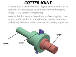
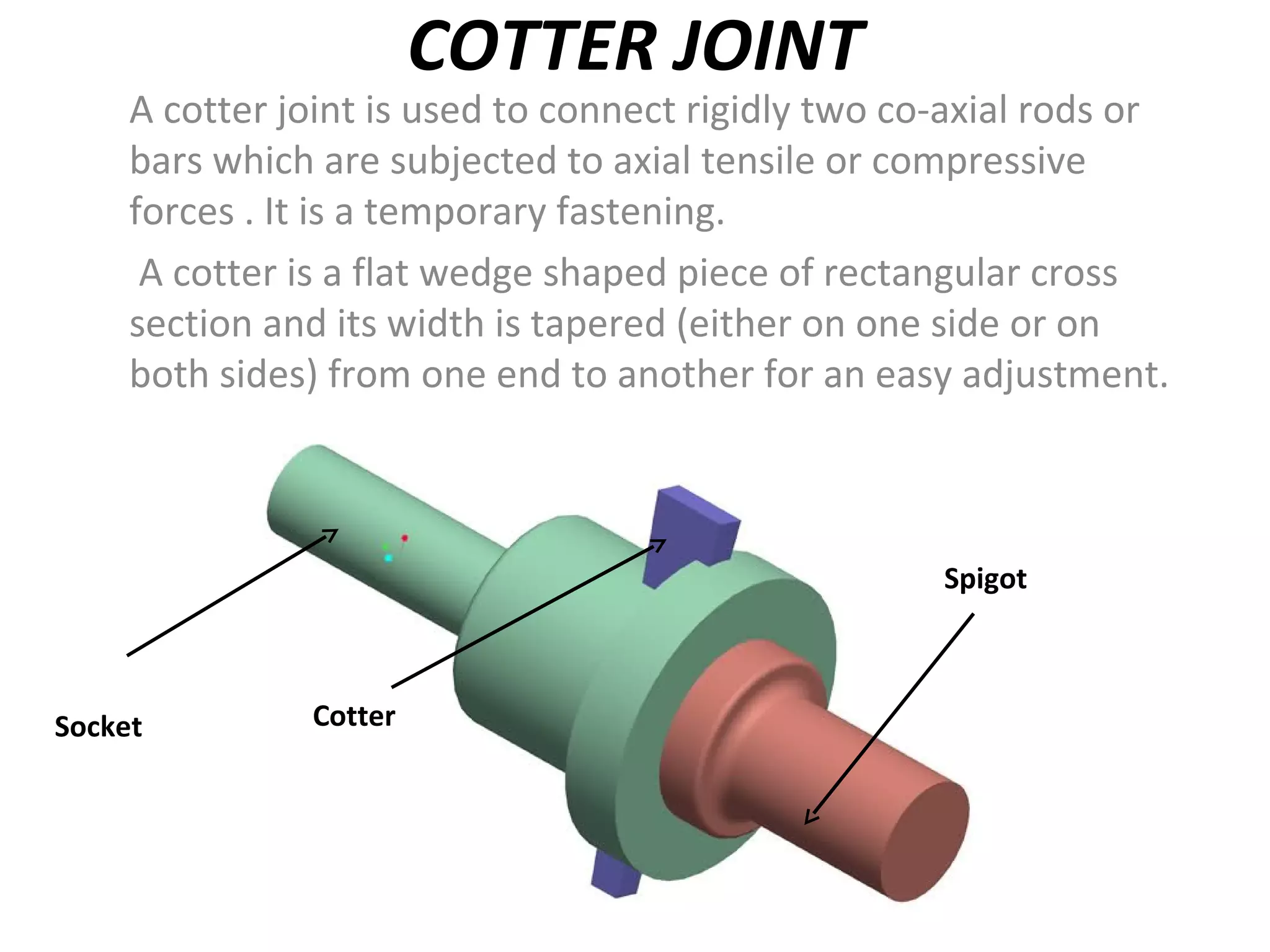
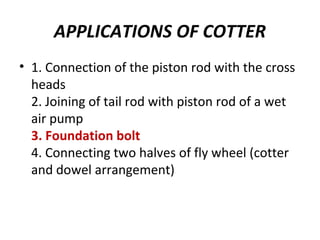
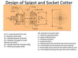
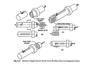
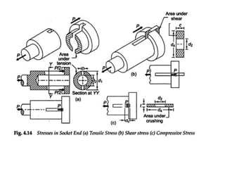
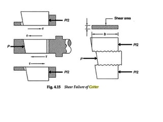
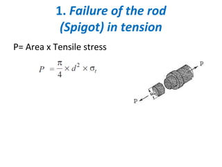
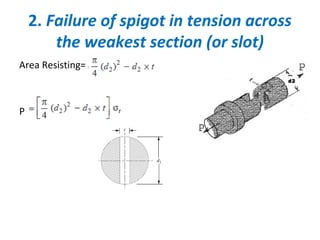
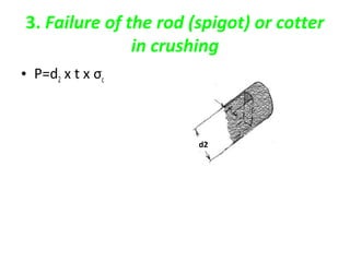
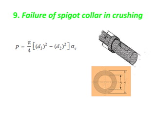
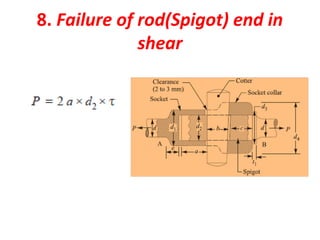
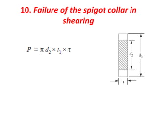
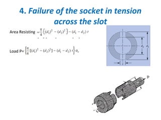
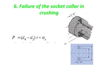
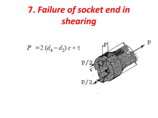
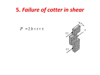
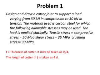
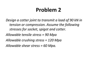
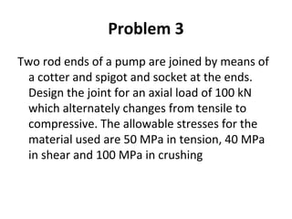
COTTER JOINT
A cotter joint is used to connect rigidly two co-axial rods or
bars which are subjected to axial tensile or compressive
forces . It is a temporary fastening.
A cotter is a flat wedge shaped piece of rectangular cross
section and its width is tapered (either on one side or on
both sides) from one end to another for an easy adjustment.
.
Socket Cotter
Spigot
APPLICATIONS OF COTTER
• 1. Connection of the piston rod with the cross
heads
2. Joining of tail rod with piston rod of a wet
air pump
3. Foundation bolt
4. Connecting two halves of fly wheel (cotter
and dowel arrangement)
Design of Spigot and Socket Cotter
Let P = Load carried by the rods,
d = Diameter of the rods,
d1 = Outside diameter of socket,
d2 = Diameter of spigot or inside
diameter of socket,
d3 = Outside diameter of spigot collar,
t1 = Thickness of spigot collar,
d4 = Diameter of socket collar,
c = Thickness of socket collar,
b = Mean width of cotter,
t = Thickness of cotter,
l = Length of cotter,
a = Distance from the end of the slot to the end of rod,
σt = Permissible tensile stress for the rods material,
τ = Permissible shear stress for the cotter material, and
σc = Permissible crushing stress for the cotter material.
1. Failure of the rod
(Spigot) in tension
P= Area x Tensile stress
2. Failure of spigot in tension across
the weakest section (or slot)
Area Resisting=
P
d2
3. Failure of the rod (spigot) or cotter
in crushing
• P=d2 x t x σc
d2
9. Failure of spigot collar in crushing
8. Failure of rod(Spigot) end in
shear
10. Failure of the spigot collar in
shearing
4. Failure of the socket in tension
across the slot
Area Resisting=
Load P=
.
6. Failure of the socket collar in
crushing
7. Failure of socket end in
shearing
5. Failure of cotter in shear
Problem 1
Design and draw a cotter joint to support a load
varying from 30 kN in compression to 30 kN in
tension. The material used is carbon steel for which
the following allowable stresses may be used. The
load is applied statically. Tensile stress = compressive
stress = 50 Mpa shear stress = 35 MPa crushing
stress= 90 MPa.
t = Thickness of cotter. It may be taken as d2/4.
The length of cotter ( l ) is taken as 4 d.
Problem 2
Design a cotter joint to transmit a load of 90 kN in
tension or compression. Assume the following
stresses for socket, spigot and cotter.
Allowable tensile stress = 90 Mpa
Allowable crushing stress = 120 Mpa
Allowable shear stress = 60 Mpa.
Problem 3
Two rod ends of a pump are joined by means of
a cotter and spigot and socket at the ends.
Design the joint for an axial load of 100 kN
which alternately changes from tensile to
compressive. The allowable stresses for the
material used are 50 MPa in tension, 40 MPa
in shear and 100 MPa in crushing

Cotter joint pptx

  • 1.
    COTTER JOINT A cotterjoint is used to connect rigidly two co-axial rods or bars which are subjected to axial tensile or compressive forces . It is a temporary fastening. A cotter is a flat wedge shaped piece of rectangular cross section and its width is tapered (either on one side or on both sides) from one end to another for an easy adjustment. . Socket Cotter Spigot
  • 2.
    APPLICATIONS OF COTTER •1. Connection of the piston rod with the cross heads 2. Joining of tail rod with piston rod of a wet air pump 3. Foundation bolt 4. Connecting two halves of fly wheel (cotter and dowel arrangement)
  • 3.
    Design of Spigotand Socket Cotter Let P = Load carried by the rods, d = Diameter of the rods, d1 = Outside diameter of socket, d2 = Diameter of spigot or inside diameter of socket, d3 = Outside diameter of spigot collar, t1 = Thickness of spigot collar, d4 = Diameter of socket collar, c = Thickness of socket collar, b = Mean width of cotter, t = Thickness of cotter, l = Length of cotter, a = Distance from the end of the slot to the end of rod, σt = Permissible tensile stress for the rods material, τ = Permissible shear stress for the cotter material, and σc = Permissible crushing stress for the cotter material.
  • 7.
    1. Failure ofthe rod (Spigot) in tension P= Area x Tensile stress
  • 8.
    2. Failure ofspigot in tension across the weakest section (or slot) Area Resisting= P d2
  • 9.
    3. Failure ofthe rod (spigot) or cotter in crushing • P=d2 x t x σc d2
  • 10.
    9. Failure ofspigot collar in crushing
  • 11.
    8. Failure ofrod(Spigot) end in shear
  • 12.
    10. Failure ofthe spigot collar in shearing
  • 13.
    4. Failure ofthe socket in tension across the slot Area Resisting= Load P= .
  • 14.
    6. Failure ofthe socket collar in crushing
  • 15.
    7. Failure ofsocket end in shearing
  • 16.
    5. Failure ofcotter in shear
  • 17.
    Problem 1 Design anddraw a cotter joint to support a load varying from 30 kN in compression to 30 kN in tension. The material used is carbon steel for which the following allowable stresses may be used. The load is applied statically. Tensile stress = compressive stress = 50 Mpa shear stress = 35 MPa crushing stress= 90 MPa. t = Thickness of cotter. It may be taken as d2/4. The length of cotter ( l ) is taken as 4 d.
  • 18.
    Problem 2 Design acotter joint to transmit a load of 90 kN in tension or compression. Assume the following stresses for socket, spigot and cotter. Allowable tensile stress = 90 Mpa Allowable crushing stress = 120 Mpa Allowable shear stress = 60 Mpa.
  • 19.
    Problem 3 Two rodends of a pump are joined by means of a cotter and spigot and socket at the ends. Design the joint for an axial load of 100 kN which alternately changes from tensile to compressive. The allowable stresses for the material used are 50 MPa in tension, 40 MPa in shear and 100 MPa in crushing