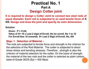
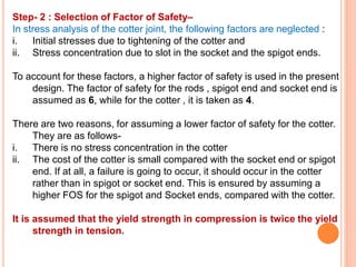
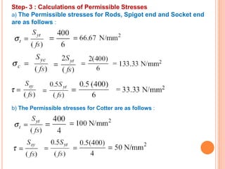
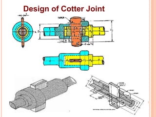
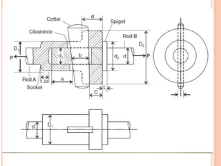
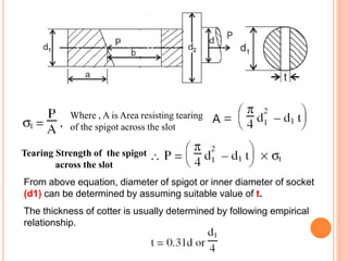
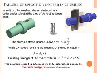
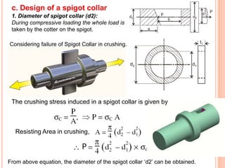
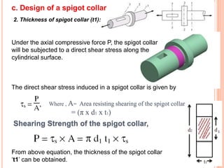
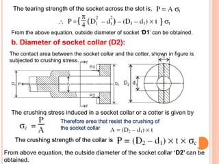
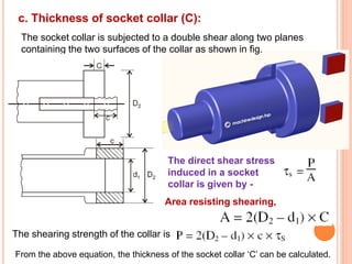
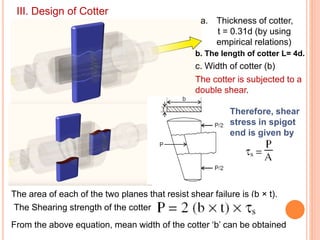
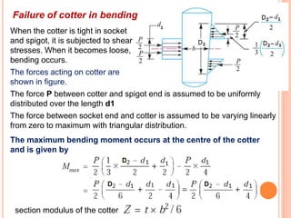
It is required to design a Cotter Joint to connect two steel rods of
equal diameter. Each rod is subjected to an axial tensile force of X
KN. Design and draw the joint and specify its main dimensions
Solution
Given : P = X kN,
Value of X= 10 x Last 2 digit of Enroll. No for enroll. No 1 to 10
For Enroll Nos 10 onwards X= Last 2 Digit of Enroll. No, KN
Step- 1 : Selection of Material –
The rods are subjected to tensile force and strength is the criterion for
the selection of the Rod Material. The cotter is subjected to direct
shear stress and bending stresses. Therefore , strength is also the
criterion of material selection for the cotter. On the basis of strength,
the material of the two rods and the cotter is selected as plain carbon
steel of Grade 30C8 (Syt = 400 Mpa)
Step- 2 : Selection of Factor of Safety–
In stress analysis of the cotter joint, the following factors are neglected :
i. Initial stresses due to tightening of the cotter and
ii. Stress concentration due to slot in the socket and the spigot ends.
To account for these factors, a higher factor of safety is used in the present
design. The factor of safety for the rods , spigot end and socket end is
assumed as 6, while for the cotter , it is taken as 4.
There are two reasons, for assuming a lower factor of safety for the cotter.
They are as follows-
i. There is no stress concentration in the cotter
ii. The cost of the cotter is small compared with the socket end or spigot
end. If at all, a failure is going to occur, it should occur in the cotter
rather than in spigot or socket end. This is ensured by assuming a
higher FOS for the spigot and Socket ends, compared with the cotter.
It is assumed that the yield strength in compression is twice the yield
strength in tension.
Step- 3 : Calculations of Permissible Stresses
a) The Permissible stresses for Rods, Spigot end and Socket end
are as follows :
b) The Permissible stresses for Cotter are as follows :
Design of Cotter Joint
I. Design of Spigot
a. Diameter of rod: Each rod of diameter ‘d’ is subjected to tensile for P
The tensile stress in the rod is given by
Area resisting tearing = (π/4) x d^2
From equation (a), diameter of the rod ‘d’ can be calculate.
SPIGOT BREAKING IN TENSION
ACROSS SLOT
b. Diameter of spigot (d1):
Since, the weakest section of the spigot
is that section which has a slot in it for
the cottar,
Where , A is Area resisting tearing
of the spigot across the slot
Tearing Strength of the spigot
across the slot
From above equation, diameter of spigot or inner diameter of socket
(d1) can be determined by assuming suitable value of t.
The thickness of cotter is usually determined by following empirical
relationship.
FAILURE OF SPIGOT OR COTTER IN CRUSHING
In addition, the crushing stress is induced in a
cotter and a spigot at the area of contact between
them.
The crushing stress induced is given by,
Where , A is Area resisting the crushing of the rod or cottar is
Crushing Strength of the rod or cottar is
This equation is used to determine the induced crushing stress, σc.
For safe design, σc induced < σc Permissible
c. Design of a spigot collar
1. Diameter of spigot collar (d2):
During compressive loading the whole load is
taken by the cotter on the spigot.
Considering failure of Spigot Collar in crushing.
The crushing stress induced in a spigot collar is given by
Resisting Area in crushing,
From above equation, the diameter of the spigot collar ‘d2’ can be obtained.
2. Thickness of spigot collar (t1):
Under the axial compressive force P, the spigot collar
will be subjected to a direct shear stress along the
cylindrical surface.
The direct shear stress induced in a spigot collar is given by
Where , A= Area resisting shearing of the spigot collar
= (π x d1 x t1)
Shearing Strength of the spigot collar,
From above equation, the thickness of the spigot collar
‘t1’ can be obtained.
c. Design of a spigot collar
d. Distance from end of slot to end of spigot
1) Shear failure:
The tail length (a) of the spigot end
much have sufficient length,
otherwise that might give way in
shearing due to the tensile load.
As the shearing takes place at two faces area under shearing
The direct shear stress induced in a spigot due to double shear is given by
So, the shearing strength of the collar is
From above equation, the distance ‘a’ can be calculated.
II. Design of Socket End
a. Outside diameter of socket (D1):
The outside diameter of the socket end is found out by considering the
tearing of the weakest section which is located where it reviews the
cotter.
The tensile stress induced in a socket cross-section, shown in figure is
given by
The tearing strength of the socket across the slot is,
From the above equation, outside diameter of socket ‘D1’ can be obtained.
b. Diameter of socket collar (D2):
The contact area between the socket collar and the cotter, shown in figure is
subjected to crushing stress.
The crushing stress induced in a socket collar or a cotter is given by
Therefore area that resist the crushing of
the socket collar
The crushing strength of the collar is
From above equation, the outside diameter of the socket collar ‘D2’ can be
obtained.
c. Thickness of socket collar (C):
The socket collar is subjected to a double shear along two planes
containing the two surfaces of the collar as shown in fig.
The direct shear stress
induced in a socket
collar is given by -
Area resisting shearing,
The shearing strength of the collar is
From the above equation, the thickness of the socket collar ‘C’ can be calculated.
III. Design of Cotter
a. Thickness of cotter,
t = 0.31d (by using
empirical relations)
c. Width of cotter (b)
The cotter is subjected to a
double shear.
The area of each of the two planes that resist shear failure is (b × t).
Therefore, shear
stress in spigot
end is given by
b. The length of cotter L= 4d.
The Shearing strength of the cotter
From the above equation, mean width of the cotter ‘b’ can be obtained
Failure of cotter in bending
When the cotter is tight in socket
and spigot, it is subjected to shear
stresses. When it becomes loose,
bending occurs.
The forces acting on cotter are
shown in figure.
The force P between cotter and spigot end is assumed to be uniformly
distributed over the length d1
The force between socket end and cotter is assumed to be varying linearly
from zero to maximum with triangular distribution.
The maximum bending moment occurs at the centre of the cotter
and is given by
section modulus of the cotter
Cotter
∴ Bending stress induced in the cotter,
This bending stress induced in the cotter should be less
than the allowable bending stress of the cotter.
 The taper in cotter should not exceed 1 in 24. In case the
greater taper is required, then a locking device must be provided.
The draw of cotter is generally taken as 2 to 3 mm.

Practical on cotter joint.pptx

  • 2.
    It is requiredto design a Cotter Joint to connect two steel rods of equal diameter. Each rod is subjected to an axial tensile force of X KN. Design and draw the joint and specify its main dimensions Solution Given : P = X kN, Value of X= 10 x Last 2 digit of Enroll. No for enroll. No 1 to 10 For Enroll Nos 10 onwards X= Last 2 Digit of Enroll. No, KN Step- 1 : Selection of Material – The rods are subjected to tensile force and strength is the criterion for the selection of the Rod Material. The cotter is subjected to direct shear stress and bending stresses. Therefore , strength is also the criterion of material selection for the cotter. On the basis of strength, the material of the two rods and the cotter is selected as plain carbon steel of Grade 30C8 (Syt = 400 Mpa)
  • 3.
    Step- 2 :Selection of Factor of Safety– In stress analysis of the cotter joint, the following factors are neglected : i. Initial stresses due to tightening of the cotter and ii. Stress concentration due to slot in the socket and the spigot ends. To account for these factors, a higher factor of safety is used in the present design. The factor of safety for the rods , spigot end and socket end is assumed as 6, while for the cotter , it is taken as 4. There are two reasons, for assuming a lower factor of safety for the cotter. They are as follows- i. There is no stress concentration in the cotter ii. The cost of the cotter is small compared with the socket end or spigot end. If at all, a failure is going to occur, it should occur in the cotter rather than in spigot or socket end. This is ensured by assuming a higher FOS for the spigot and Socket ends, compared with the cotter. It is assumed that the yield strength in compression is twice the yield strength in tension.
  • 4.
    Step- 3 :Calculations of Permissible Stresses a) The Permissible stresses for Rods, Spigot end and Socket end are as follows : b) The Permissible stresses for Cotter are as follows :
  • 5.
  • 7.
    I. Design ofSpigot a. Diameter of rod: Each rod of diameter ‘d’ is subjected to tensile for P The tensile stress in the rod is given by Area resisting tearing = (π/4) x d^2 From equation (a), diameter of the rod ‘d’ can be calculate.
  • 8.
    SPIGOT BREAKING INTENSION ACROSS SLOT b. Diameter of spigot (d1): Since, the weakest section of the spigot is that section which has a slot in it for the cottar,
  • 9.
    Where , Ais Area resisting tearing of the spigot across the slot Tearing Strength of the spigot across the slot From above equation, diameter of spigot or inner diameter of socket (d1) can be determined by assuming suitable value of t. The thickness of cotter is usually determined by following empirical relationship.
  • 10.
    FAILURE OF SPIGOTOR COTTER IN CRUSHING In addition, the crushing stress is induced in a cotter and a spigot at the area of contact between them. The crushing stress induced is given by, Where , A is Area resisting the crushing of the rod or cottar is Crushing Strength of the rod or cottar is This equation is used to determine the induced crushing stress, σc. For safe design, σc induced < σc Permissible
  • 11.
    c. Design ofa spigot collar 1. Diameter of spigot collar (d2): During compressive loading the whole load is taken by the cotter on the spigot. Considering failure of Spigot Collar in crushing. The crushing stress induced in a spigot collar is given by Resisting Area in crushing, From above equation, the diameter of the spigot collar ‘d2’ can be obtained.
  • 12.
    2. Thickness ofspigot collar (t1): Under the axial compressive force P, the spigot collar will be subjected to a direct shear stress along the cylindrical surface. The direct shear stress induced in a spigot collar is given by Where , A= Area resisting shearing of the spigot collar = (π x d1 x t1) Shearing Strength of the spigot collar, From above equation, the thickness of the spigot collar ‘t1’ can be obtained. c. Design of a spigot collar
  • 13.
    d. Distance fromend of slot to end of spigot 1) Shear failure: The tail length (a) of the spigot end much have sufficient length, otherwise that might give way in shearing due to the tensile load.
  • 14.
    As the shearingtakes place at two faces area under shearing The direct shear stress induced in a spigot due to double shear is given by So, the shearing strength of the collar is From above equation, the distance ‘a’ can be calculated.
  • 15.
    II. Design ofSocket End
  • 16.
    a. Outside diameterof socket (D1): The outside diameter of the socket end is found out by considering the tearing of the weakest section which is located where it reviews the cotter. The tensile stress induced in a socket cross-section, shown in figure is given by
  • 17.
    The tearing strengthof the socket across the slot is, From the above equation, outside diameter of socket ‘D1’ can be obtained. b. Diameter of socket collar (D2): The contact area between the socket collar and the cotter, shown in figure is subjected to crushing stress. The crushing stress induced in a socket collar or a cotter is given by Therefore area that resist the crushing of the socket collar The crushing strength of the collar is From above equation, the outside diameter of the socket collar ‘D2’ can be obtained.
  • 18.
    c. Thickness ofsocket collar (C): The socket collar is subjected to a double shear along two planes containing the two surfaces of the collar as shown in fig. The direct shear stress induced in a socket collar is given by - Area resisting shearing, The shearing strength of the collar is From the above equation, the thickness of the socket collar ‘C’ can be calculated.
  • 19.
    III. Design ofCotter a. Thickness of cotter, t = 0.31d (by using empirical relations) c. Width of cotter (b) The cotter is subjected to a double shear. The area of each of the two planes that resist shear failure is (b × t). Therefore, shear stress in spigot end is given by b. The length of cotter L= 4d. The Shearing strength of the cotter From the above equation, mean width of the cotter ‘b’ can be obtained
  • 20.
    Failure of cotterin bending When the cotter is tight in socket and spigot, it is subjected to shear stresses. When it becomes loose, bending occurs. The forces acting on cotter are shown in figure. The force P between cotter and spigot end is assumed to be uniformly distributed over the length d1 The force between socket end and cotter is assumed to be varying linearly from zero to maximum with triangular distribution. The maximum bending moment occurs at the centre of the cotter and is given by section modulus of the cotter
  • 21.
    Cotter ∴ Bending stressinduced in the cotter, This bending stress induced in the cotter should be less than the allowable bending stress of the cotter.  The taper in cotter should not exceed 1 in 24. In case the greater taper is required, then a locking device must be provided. The draw of cotter is generally taken as 2 to 3 mm.

Editor's Notes