Definitions, Nomenclature,
Classifications, Comparisonbetween
keys and cotters, Design of Socket
and spigot cotter joint, Sleeve type
Cotter joint, Cotter with Gib, Knuckle
Joint, Suspension link, Pin joint,
Adjustable joint, Turn-buckle.
UNIT-III
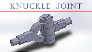
Cotter Joint
and Knuckle
Joints
2.
WEDGE
A wedge isa triangular
shaped tool made of
wood or iron, that
tapers to a thin edge
and is used for splitting
wood and rocks (chisel),
raising heavy load
(inclined plane) or for
tightening by being
driven into something.
3.
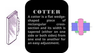
COTTER
A cotter isa flat wedge-
shaped piece of
rectangular cross-
section and its width is
tapered (either on one
side or both sides) from
one end to another for
an easy adjustment.
4.
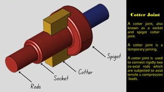
Cotter Joint
A cotterjoint, also
known as a socket
and spigot cotter
joint.
A cotter joint is a
temporary joining.
A cotter joint is used
to connect rigidly two
co-axial rods which
are subjected to axial
tensile & compression
loads.
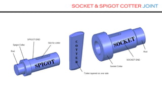
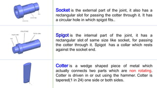
Socket is theexternal part of the joint, it also has a
rectangular slot for passing the cotter through it. It has
a circular hole in which spigot fits..
Spigot is the internal part of the joint, it has a
rectangular slot of same size like socket, for passing
the cotter through it. Spigot has a collar which rests
against the socket end.
Cotter is a wedge shaped piece of metal which
actually connects two parts which are non rotating.
Cotter is driven in or out using the hammer. Cotter is
tapered(1 in 24) one side or both sides.
8.
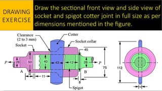
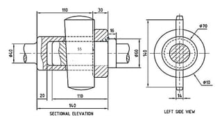
Draw the sectionalfront view and side view of
socket and spigot cotter joint in full size as per
dimensions mentioned in the figure.
DRAWING
EXERCISE
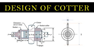
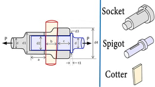
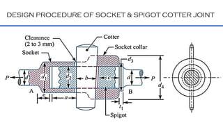
DESIGN PROCEDURE OFSOCKET & SPIGOT COTTER JOINT
P = Load on the rods [pull or push]
d = Diameter of the rod
d1 = Outer diameter of socket
d2 = Diameter of spigot/ Internal dia. of socket
d3 = Diameter of spigot collar
d4 = Diameter of socket collar
t1 = Thickness of spigot collar
a = Distance from end of slot to end of spigot
c = Thickness of socket collar
b, t & l = Mean width, thickness & length of cotter
13.
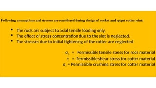
Following assumptions andstresses are considered during design of socket and spigot cotter joint:
The rods are subject to axial tensile loading only.
The effect of stress concentration due to the slot is neglected.
The stresses due to initial tightening of the cotter are neglected
σt = Permissible tensile stress for rods material
τ = Permissible shear stress for cotter material
σc = Permissible crushing stress for cotter material
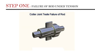
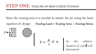
STEP ONE :FAILURE OF ROD UNDER TENSION
Since the tearing area is a circular in nature. So, by using the basic
equation of design Tearing Load = Tearing Area x Tearing Stress
P =
π
4
d2 σt
by this relation,
diameter of rod d will
determined
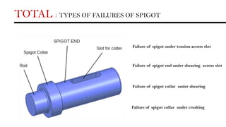
Failure of spigotunder tension across slot
Failure of spigot end under shearing across slot
Failure of spigot collar under shearing
Failure of spigot collar under crushing
TOTAL : TYPES OF FAILURES OF SPIGOT
19.
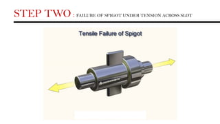
STEP TWO :FAILURE OF SPIGOT UNDER TENSION ACROSS SLOT
20.
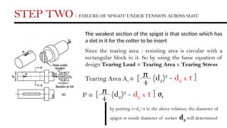
STEP TWO :FAILURE OF SPIGOT UNDER TENSION ACROSS SLOT
The weakest section of the spigot is that section which has
a slot in it for the cotter to be insert
Since the tearing area / resisting area is circular with a
rectangular block in it. So by using the basic equation of
design Tearing Load = Tearing Area x Tearing Stress
Tearing Area At =
π
4
(d2)2
- d2 x t
[
[
P = π
4
(d2)2
- d2 x t
[
[
σt
by putting t=d2/4 in the above relation, the diameter of
spigot or inside diameter of socket d2 will determined
21.
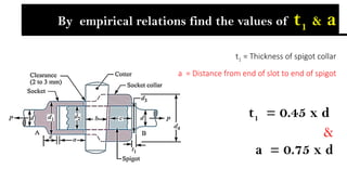
t1 = 0.45x d
&
a = 0.75 x d
By empirical relations find the values of t1 & a
t1 = Thickness of spigot collar
a = Distance from end of slot to end of spigot
22.
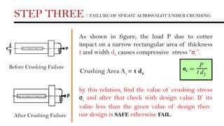
STEP THREE :FAILURE OF SPIGOT ACROSS SLOT UNDER CRUSHING
Before Crushing Failure
After Crushing Failure
As shown in figure, the load P due to cotter
impact on a narrow rectangular area of thickness
t and width d2 causes compressive stress “σc”.
by this relation, find the value of crushing stress
σc and after that check with design value. If its
value less than the given value of design then
our design is SAFE otherwise FAIL.
Crushing Area Ac = t d2
23.
STEP FOUR :FAILURE OF SPIGOT END UNDER SHEARING ACROSS SLOT
The figure is shows the shear failure of
spigot end is in double shear [i.e. two
shear planes]
Ac = 2 (a d2) P = 2 a d2
Find the value of shearing stress by
this relation and check it to safe
design.
24.
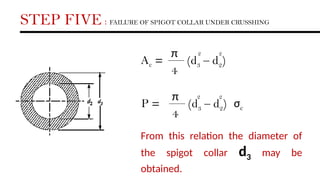
STEP FIVE :FAILURE OF SPIGOT COLLAR UNDER CRUSSHING
Ac =
π
4
(d3 – d2)
2 2
P =
π
4
(d3 – d2)
2 2
σc
From this relation the diameter of
the spigot collar d3 may be
obtained.
25.
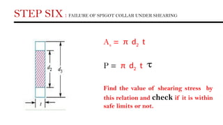
As = πd2 t
P = π d2 t
Find the value of shearing stress by
this relation and check if it is within
safe limits or not.
STEP SIX : FAILURE OF SPIGOT COLLAR UNDER SHEARING
26.
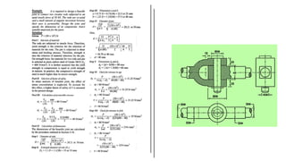
DESIGN OF SOCKET
Failureof socket under
tension across slot
Failure of socket end [collar]
under shearing across slot
Failure of socket collar
under crushing
X1
X1
27.
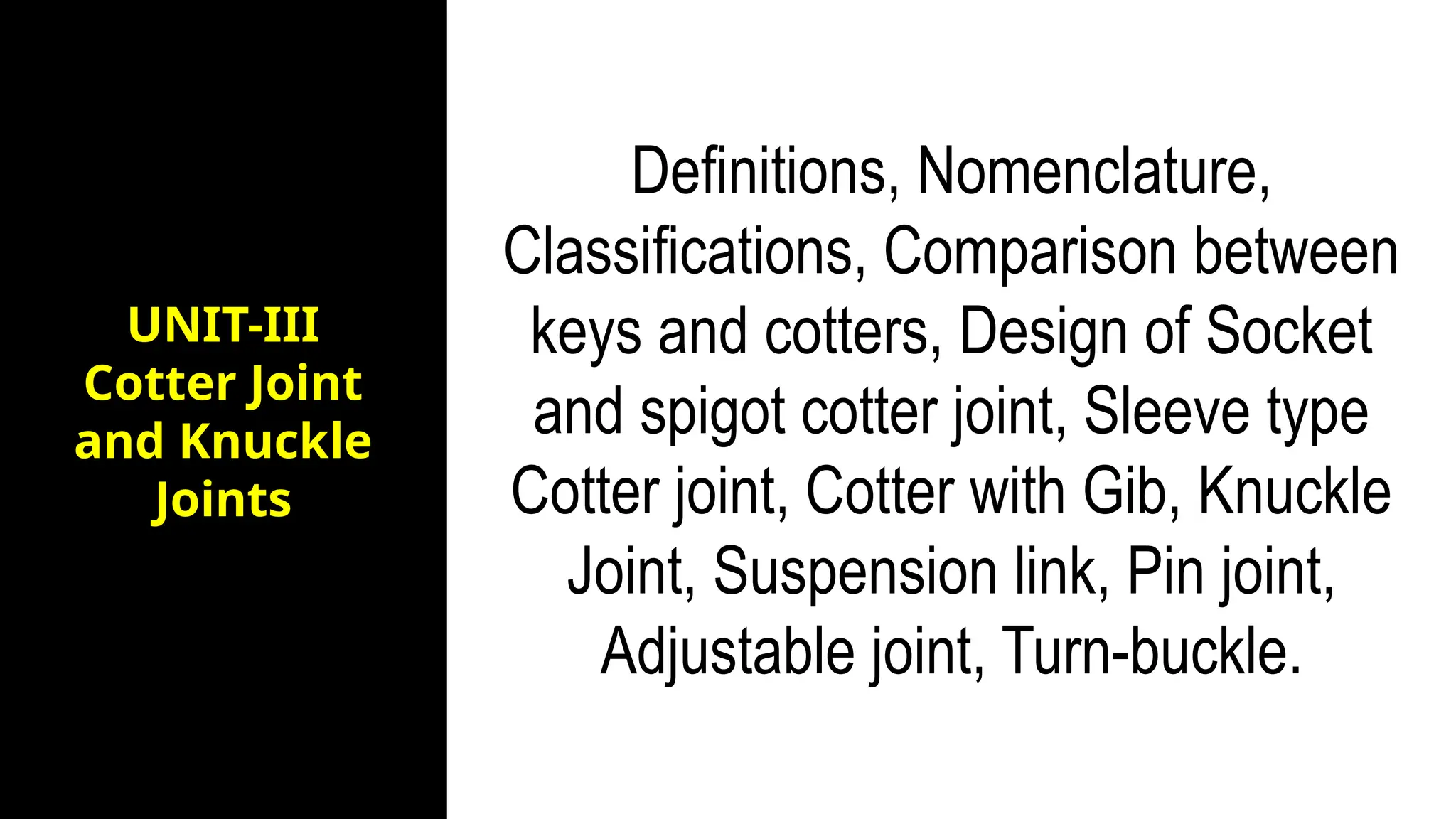
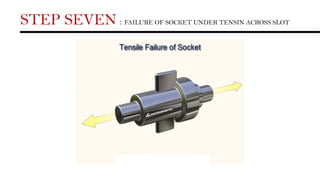
STEP SEVEN :FAILURE OF SOCKET UNDER TENSIN ACROSS SLOT
28.
STEP SEVEN :FAILURE OF SOCKET UNDER TENSIN ACROSS SLOT
The socket may also fail under
tension into two parts as shown in
figure. Since the plane of failure is
perpendicular to direction of load.
by this relation, the diameter of
socket collar d1 will determined.
At = { [(d1)2
- (d2)2
] - (d1 - d2)t}
π
4
P = { [(d1)2
- (d2)2
] - (d1 - d2) t}σt
π
4
29.
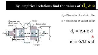
d4 = Diameterof socket collar
c = Thickness of socket collar
d4 = 2.4 x d
&
c = 0.75 x d
By empirical relations find the values of d4 & c
30.
d4 d2
Area undercrushing
t
Ac = [d4 – d2] t
P = [d4 – d2] t σc
By this relation, the induced crushing
stress may be checked (i.e. it must be
less than given design value)
STEP EIGHT : FAILURE OF SOCKET COLLAR UNDER CRUSHING
31.
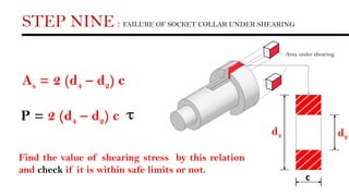
STEP NINE :FAILURE OF SOCKET COLLAR UNDER SHEARING
As = 2 (d4 – d2) c
Area under shearing
d2
d4
c
P = 2 (d4 – d2) c
Find the value of shearing stress by this relation
and check if it is within safe limits or not.
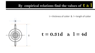
t = 0.31d& l = 4d
t = thickness of cotter & l = length of cotter
l
t
By empirical relations find the values of t & l
34.
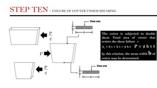
STEP TEN :FAILURE OF COTTER UNDER SHEARING
P
2
P
2
P
The cotter is subjected to double
shear. Total area of cotter that
resists the shear failure =
As = b t + b t = 2 b t P = 2 b t τ
by this relation, the mean width b of
cotter may be determined.
35.
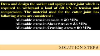
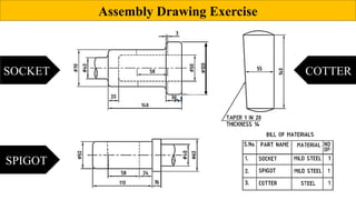
Draw and designthe socket and spigot cotter joint which is
required to withstand a load of 30 kN in tension and
compression. The material used for the cotter joint has
following stress are considered :
Allowable stress in tension = 50 MPa
Allowable stress in Shear Stress = 35 MPa
Allowable stress in Crushing stress= 90 MPa
SOLUTION STEPS
37.
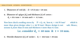
1. Diameters ofrod (d) : d = 27.6 mm ≈ 28 mm
2. Diameter of spigot (d2) and thickness (t) of cotter :
d2 = 33.4 mm ≈ 34 mm and t = 8.5 mm .
Now here check crushing stress by P = d2 t σc here σc = 103 N/mm2
which is
more than given design value i. e. 90 N/mm2
. Hence design is not safe. Hence,
assume d2 more than 34 mm and thickness t more than 8.5 mm
i.e. consider d2 = 40 mm & t = 10 mm.
3. Outside diameter (d1) of socket : d1 = 49.9 mm ≈ 50 mm
S O L U T I O N S T E P S C O N T I N U E
38.
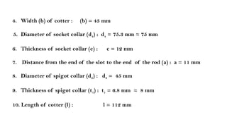
4. Width (b)of cotter : (b) = 43 mm
5. Diameter of socket collar (d4) : d4 = 75.3 mm ≈ 75 mm
6. Thickness of socket collar (c) : c = 12 mm
7. Distance from the end of the slot to the end of the rod (a) : a = 11 mm
8. Diameter of spigot collar (d3) : d3 = 45 mm
9. Thickness of spigot collar (t1) : t1 = 6.8 mm ≈ 8 mm
10. Length of cotter (l) : l = 112 mm
R O D1 F I E X D P O S I T I O N
R O D 2 F I R S T P O S I T I O N
R
O
D
2
F
I
N
A
L
P
O
S
I
T
I
O
N
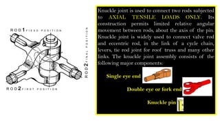
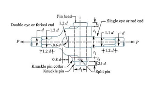
Knuckle joint is used to connect two rods subjected
to AXIAL TENSILE LOADS ONLY. Its
construction permits limited relative angular
movement between rods, about the axis of the pin.
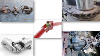
Knuckle joint is widely used to connect valve rod
and eccentric rod, in the link of a cycle chain,
levers, tie rod joint for roof truss and many other
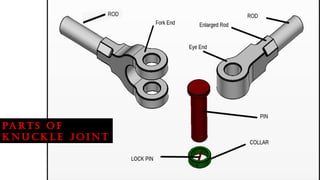
links. The knuckle joint assembly consists of the
following major components:
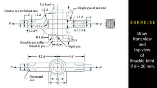
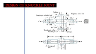
Single eye end
Double eye or fork end
Knuckle pin
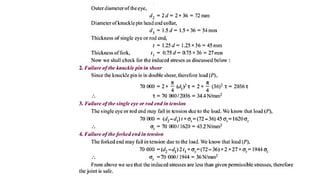
Design OF KNUCKLEJOINT
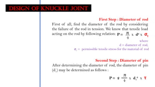
First Step : Diameter of rod
First of all, find the diameter of the rod by considering
the failure of the rod in tension. We know that tensile load
acting on the rod by following relation: P = x d2
x σt
π
4
where
d = diameter of rod,
σt = permissible tensile stress for the material of rod
Second Step : Diameter of pin
After determining the diameter of rod, the diameter of pin
(d1) may be determined as follows :
P = 2 x d1
2
x τ
π
4
46.
Design OF KNUCKLEJOINT
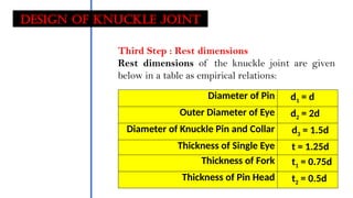
Third Step : Rest dimensions
Rest dimensions of the knuckle joint are given
below in a table as empirical relations:
Diameter of Pin d1 = d
Outer Diameter of Eye d2 = 2d
Diameter of Knuckle Pin and Collar d3 = 1.5d
Thickness of Single Eye t = 1.25d
Thickness of Fork t1 = 0.75d
Thickness of Pin Head t2 = 0.5d
47.
Design OF KNUCKLEJOINT
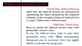
Fourth Step : Induced Stresses
After that, the induced stresses are calculated by
substituting the values obtained by the empirical
relations, in the strength relation of load and area
i.e. load = failure area x induced stress
Fifth Step : Check Point
Here we checks the induced stresses value with
permissible stresses value.
In case the induced stress value is more than
permissible stress value then corresponding
dimensions may be increased. After that again
check it and make the design safe.
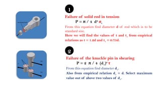
Failure of solidrod in tension
P = π / 4 d2
σt
From this equation find diameter d of rod which is to be
standard size.
Here we will find the values of t and t1 from empirical
relations as t = 1.2d and t1 = 0.75d.
1
Failure of the knuckle pin in shearing
P = 2 π / 4 (d1)2
τ
From this equation find diameter d1.
Also from empirical relation d1 = d. Select maximum
value out of above two values of d1.
2
50.
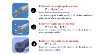
Failure of singleeye in shearing
P = 2 x (d2 – d1) t τ
From this equation check the value of τ should be less
than permissible value.
Failure of the single eye in crushing
P = d1 t σc
From this equation check the value of σc should be less
than permissible value.
5
4
Failure of the single eye in tension
P = (d2 – d1) t σt
From this equation find diameter d2.
Also from empirical relation d2 = 2d. Select maximum
value out of above two values of d2
3
51.
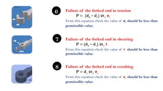
Failure of theforked end in shearing
P = (d2 – d1) 2t1 τ
From this equation check the value of τ should be less than
permissible value.
Failure of the forked end in crushing
P = d1 2t1 σc
From this equation check the value of σc should be less than
permissible value.
8
7
Failure of the forked end in tension
P = (d2 – d1) 2t1 σt
From this equation check the value of σt should be less than
permissible value.
6
52.
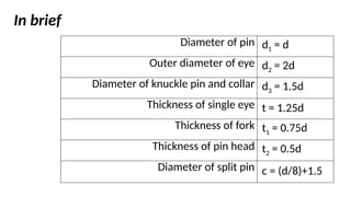
Diameter of pind1 = d
Outer diameter of eye d2 = 2d
Diameter of knuckle pin and collar d3 = 1.5d
Thickness of single eye t = 1.25d
Thickness of fork t1 = 0.75d
Thickness of pin head t2 = 0.5d
Diameter of split pin c = (d/8)+1.5
In brief
53.
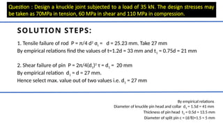
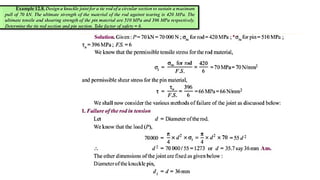
Question : Designa knuckle joint subjected to a load of 35 kN. The design stresses may
be taken as 70MPa in tension, 60 MPa in shear and 110 MPa in compression.
SOLUTION STEPS:
1. Tensile failure of rod P = π/4 d2
σt = d = 25.23 mm. Take 27 mm
By empirical relations find the values of t=1.2d = 33 mm and t1 = 0.75d = 21 mm
2. Shear failure of pin P = 2π/4(d1)2
τ = d1 = 20 mm
By empirical relation d1 = d = 27 mm.
Hence select max. value out of two values i.e. d1 = 27 mm
By empirical relations
Diameter of knuckle pin head and collar d3 = 1.5d = 41 mm
Thickness of pin head t2 = 0.5d = 13.5 mm
Diameter of split pin c = (d/8)+1.5 = 5 mm
54.
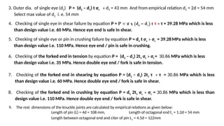
3. Outer dia.of single eye (d2) P = (d2 – d1) t σt » d2 = 43 mm And from empirical relation d2 = 2d = 54 mm
Select max value of d2 i. e. 54 mm
4. Checking of single eye in shear failure by equation P = P = 2 x (d2 – d1) t τ » τ = 39.28 MPa which is less
than design value i.e. 60 MPa. Hence eye end is safe in shear.
5. Checking of single eye or pin in crushing failure by equation P = d1 t σc » σc = 39.28MPa which is less
than design value i.e. 110 MPa. Hence eye end / pin is safe in crushing.
6. Checking of the forked end in tension by equation P = (d2 – d1) 2t1 σt » σt = 30.86 MPa which is less
than design value i.e. 35 MPa. Hence double eye end / fork is safe in tension.
7. Checking of the forked end in shearing by equation P = (d2 – d1) 2t1 τ » τ = 30.86 MPa which is less
than design value i.e. 60 MPa. Hence double eye end / fork is safe in shear.
8. Checking of the forked end in crushing by equation P = d1 2t1 σc » σc = 30.86 MPa which is less than
design value i.e. 110 MPa. Hence double eye end / fork is safe in shear.
9. The rest dimensions of the knuckle joints are calculated by empirical relations as given below:
Length of pin (L) = 4d = 108 mm, Length of octagonal end l1 = 1.2d = 54 mm
Length between octagonal end and citer of pin L1 = 4.5d = 122mm


![DESIGN PROCEDURE OF SOCKET & SPIGOT COTTER JOINT
P = Load on the rods [pull or push]
d = Diameter of the rod
d1 = Outer diameter of socket
d2 = Diameter of spigot/ Internal dia. of socket
d3 = Diameter of spigot collar
d4 = Diameter of socket collar
t1 = Thickness of spigot collar
a = Distance from end of slot to end of spigot
c = Thickness of socket collar
b, t & l = Mean width, thickness & length of cotter](https://image.slidesharecdn.com/cotterandknucklejoints-250429090941-10fc9892/85/COTTER-and-KNUCKleeeeeeeeeeeeeeeeeee-pptx-12-320.jpg)


![STEP FOUR : FAILURE OF SPIGOT END UNDER SHEARING ACROSS SLOT
The figure is shows the shear failure of
spigot end is in double shear [i.e. two
shear planes]
Ac = 2 (a d2) P = 2 a d2
Find the value of shearing stress by
this relation and check it to safe
design.](https://image.slidesharecdn.com/cotterandknucklejoints-250429090941-10fc9892/85/COTTER-and-KNUCKleeeeeeeeeeeeeeeeeee-pptx-23-320.jpg)
![DESIGN OF SOCKET
Failure of socket under
tension across slot
Failure of socket end [collar]
under shearing across slot
Failure of socket collar
under crushing
X1
X1](https://image.slidesharecdn.com/cotterandknucklejoints-250429090941-10fc9892/85/COTTER-and-KNUCKleeeeeeeeeeeeeeeeeee-pptx-26-320.jpg)
![STEP SEVEN : FAILURE OF SOCKET UNDER TENSIN ACROSS SLOT
The socket may also fail under
tension into two parts as shown in
figure. Since the plane of failure is
perpendicular to direction of load.
by this relation, the diameter of
socket collar d1 will determined.
At = { [(d1)2
- (d2)2
] - (d1 - d2)t}
π
4
P = { [(d1)2
- (d2)2
] - (d1 - d2) t}σt
π
4](https://image.slidesharecdn.com/cotterandknucklejoints-250429090941-10fc9892/85/COTTER-and-KNUCKleeeeeeeeeeeeeeeeeee-pptx-28-320.jpg)
![d4 d2
Area under crushing
t
Ac = [d4 – d2] t
P = [d4 – d2] t σc
By this relation, the induced crushing
stress may be checked (i.e. it must be
less than given design value)
STEP EIGHT : FAILURE OF SOCKET COLLAR UNDER CRUSHING](https://image.slidesharecdn.com/cotterandknucklejoints-250429090941-10fc9892/85/COTTER-and-KNUCKleeeeeeeeeeeeeeeeeee-pptx-30-320.jpg)