Downloaded 107 times
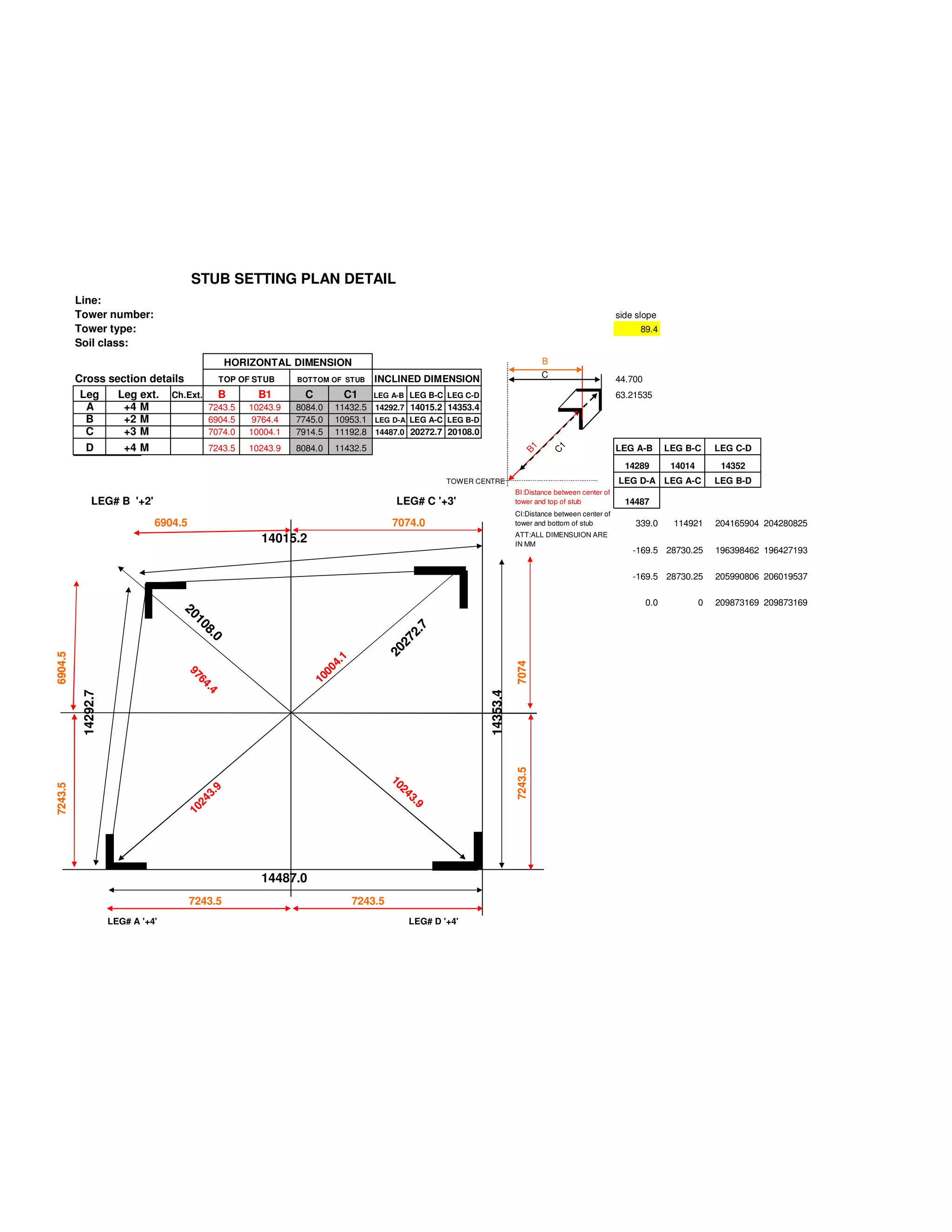

This document provides details of a stub setting plan for a transmission tower, including: - Horizontal and inclined dimensions for the tops and bottoms of each of the four tower legs (A, B, C, D) - Lengths of each leg segment between connection points - Distances from the tower center to the top and bottom of each stub - Notes that all dimensions are in millimeters


![Amp 250w mono[1]](https://cdn.slidesharecdn.com/ss_thumbnails/amp250wmono1-121227125036-phpapp01-thumbnail.jpg?width=640&height=640&fit=bounds)


![Vibe Coding vs. Spec-Driven Development [Free Meetup]](https://cdn.slidesharecdn.com/ss_thumbnails/vibecodingvsspecdrivendevelopment-251209105622-43f455e7-thumbnail.jpg?width=640&height=640&fit=bounds)


