Download to read offline
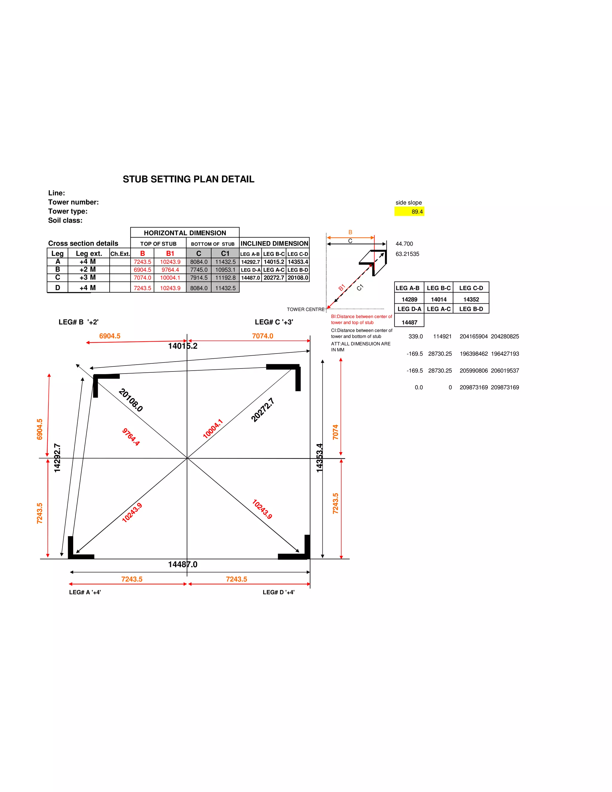

This document contains details of a stub setting plan for a transmission tower, including: 1) Horizontal and inclined dimensions for the tops and bottoms of each of the four tower legs (A, B, C, D) which are set at different heights (+4m, +2m, +3m, +4m). 2) Dimensions for the lengths of each leg (A-B, B-C, C-D, D-A, A-C, B-D) and their angles. 3) Notes indicating all dimensions are in millimeters and other geometric details like the distance from the tower center to the top and bottom of each stub.


