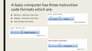
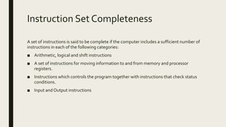
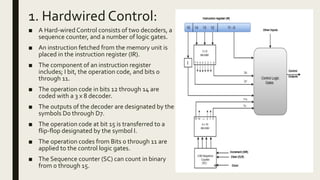
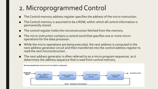
2. An instruction comprises of groups
called fields.These fields include:
■ The Operation code (Opcode) field which specifies the operation to be performed.
■ The Address field which contains the location of the operand, i.e., register or memory
location.
■ The Mode field which specifies how the operand will be located.
3. A basic computer has three instruction
code formats which are:
■ Memory - reference instruction
■ Register - reference instruction
■ Input-Output instruction
4. Instruction Set Completeness
A set of instructions is said to be complete if the computer includes a sufficient number of
instructions in each of the following categories:
■ Arithmetic, logical and shift instructions
■ A set of instructions for moving information to and from memory and processor
registers.
■ Instructions which controls the program together with instructions that check status
conditions.
■ Input and Output instructions
5. Design of Control Unit
The Control Unit is classified into two major categories:
■ Hardwired Control
■ Microprogrammed Control
6. 1. Hardwired Control:
■ A Hard-wired Control consists of two decoders, a
sequence counter, and a number of logic gates.
■ An instruction fetched from the memory unit is
placed in the instruction register (IR).
■ The component of an instruction register
includes; I bit, the operation code, and bits 0
through 11.
■ The operation code in bits 12 through 14 are
coded with a 3 x 8 decoder.
■ The outputs of the decoder are designated by the
symbols D0 through D7.
■ The operation code at bit 15 is transferred to a
flip-flop designated by the symbol I.
■ The operation codes from Bits 0 through 11 are
applied to the control logic gates.
■ The Sequence counter (SC) can count in binary
from 0 through 15.
7. 2. Microprogrammed Control
■ The Control memory address register specifies the address of the micro-instruction.
■ The Control memory is assumed to be a ROM, within which all control information is
permanently stored.
■ The control register holds the microinstruction fetched from the memory.
■ The micro-instruction contains a control word that specifies one or more micro-
operations for the data processor.
■ While the micro-operations are being executed, the next address is computed in the
next address generator circuit and then transferred into the control address register to
read the next microinstruction.
■ The next address generator is often referred to as a micro-program sequencer, as it
determines the address sequence that is read from control memory.
Editor's Notes
Computer instructions are a set of machine language instructions that a particular processor understands and executes. A computer performs tasks on the basis of the instruction provided.
In Memory-reference instruction, 12 bits of memory is used to specify an address and one bit to specify the addressing mode ‘I’.
The Register-reference instructions are represented by the Opcode 111 with a 0 in the leftmost bit (bit 15) of the instruction.
A Register-reference instruction specifies an operation on or a test of the AC (Accumulator) register.
Just like the Register-reference instruction, an Input-Output instruction does not need a reference to memory and is recognized by the operation code 111 with a 1 in the leftmost bit of the instruction. The remaining 12 bits are used to specify the type of the input-output operation or test performed.
The Microprogrammed Control organization is implemented by using the programming approach.
In Microprogrammed Control, the micro-operations are performed by executing a program consisting of micro-instructions.
The following image shows the block diagram of a Microprogrammed Control organization.