Computer Communication Networks-Network Layer
•
0 likes•107 views

VTU 6 SEM EC (15/17EC64)

Recommended
More Related Content
What's hot
What's hot (20)
Similar to Computer Communication Networks-Network Layer
Similar to Computer Communication Networks-Network Layer (20)
More from Krishna Nanda
More from Krishna Nanda (15)
Recently uploaded
Recently uploaded (20)
Computer Communication Networks-Network Layer
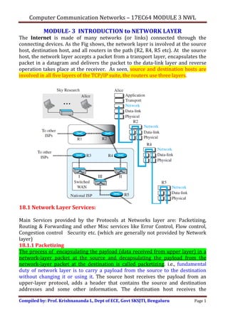
- 1. Computer Communication Networks – 17EC64 MODULE 3 NWL Compiled by: Prof. Krishnananda L, Dept of ECE, Govt SKSJTI, Bengaluru Page 1 MODULE- 3 INTRODUCTION to NETWORK LAYER The Internet is made of many networks (or links) connected through the connecting devices. As the Fig shows, the network layer is involved at the source host, destination host, and all routers in the path (R2, R4, R5 etc). At the source host, the network layer accepts a packet from a transport layer, encapsulates the packet in a datagram and delivers the packet to the data-link layer and reverse operation takes place at the receiver. As seen, source and destination hosts are involved in all five layers of the TCP/IP suite, the routers use three layers. 18.1 Network Layer Services: Main Services provided by the Protocols at Networks layer are: Packetizing, Routing & Forwarding and other Misc services like Error Control, Flow control, Congestion control Security etc. (which are generally not provided by Network layer) 18.1.1 Packetizing The process of encapsulating the payload (data received from upper layer) in a network-layer packet at the source and decapsulating the payload from the network-layer packet at the destination is called packetizing. i.e., fundamental duty of network layer is to carry a payload from the source to the destination without changing it or using it. The source host receives the payload from an upper-layer protocol, adds a header that contains the source and destination addresses and some other information. The destination host receives the
- 2. Computer Communication Networks – 17EC64 MODULE 3 NWL Compiled by: Prof. Krishnananda L, Dept of ECE, Govt SKSJTI, Bengaluru Page 2 network-layer packet from its data-link layer, decapsulates the packet, and delivers the payload to the corresponding upper-layer protocol. If the packet is fragmented at the source or at routers along the path, the network layer at destination waits until all fragments arrive, reassembles them, and delivers to the upper-layer protocol. If a packet is fragmented, the header needs to be copied to all fragments. 18.1.2 Routing and Forwarding 1) Routing The network layer is responsible for routing the packet from its source to the destination. A physical network is a combination of networks (LANs and WANs) and routers that connect them. This means that there is more than one route from the source to the destination. Finding the best path (using certain algorithms) for the packet to reach the destination is called Routing. So, routing is applying some strategies and running some routing protocols to create the decision-making tables for each router. 2) Forwarding Forwarding can be defined as the action applied by each router when a packet arrives at one of its interfaces. The decision-making table is called the forwarding table or the routing table. When a router receives a packet from one of its attached networks, it needs to forward the packet to another attached network (in unicast routing) or to some attached networks (in multicast routing). To make this decision, the router uses some information in the packet header (the destination address or a label), to find the corresponding output interface number in the forwarding table. Fig. shows the idea of the forwarding process in a router. 18.1.3 Other Services: Error Control Not Provided by Network Layer. Packet in the network layer may be fragmented at each router, which makes error checking at this layer inefficient. However, a checksum field is added to the datagram to control
- 3. Computer Communication Networks – 17EC64 MODULE 3 NWL Compiled by: Prof. Krishnananda L, Dept of ECE, Govt SKSJTI, Bengaluru Page 3 any corruption in the header, but not in the whole datagram. The Internet uses an auxiliary protocol, ICMP, that provides some kind of error control Flow Control Flow control regulates the amount of data a source can send without overwhelming the receiver. Not provided by Network layer. Provided by both DLL and Transport Layer Congestion Control Congestion in the network layer is a situation in which too many datagrams are present in an area of the Internet. i.e., the number of datagrams sent by source is beyond the capacity of the network or routers. So some mechanism for controlling congestion is needed, However, not implemented in Network layer, but in Transport layer. Quality of Service (QoS) Implemented & supported by upper layers, not in network layer. Security Not supported directly by the network layer in the Internet. However, a special provision called IPSec is made in the Internet. 18.2 PACKET SWITCHING A router, in fact, is a switch that creates a connection between an input port and an output port (or a set of output ports). The source sends the packets one by one; the destination waits for all packets belonging to the same message to arrive. The connecting devices in a packet-switched network need to decide how to route the packets to the final destination. Packet-switched networks use two different approaches to route the packets: the datagram approach and the virtual circuit approach. 18.2.1 Datagram Approach: Connectionless Service The network layer in the Internet was designed to provide a connectionless service i.e, the protocol treats each packet independently; there is no relationship between packets belonging to the same message. The packets in a message may or may not travel the same path to their destination. Figure 18.3 shows the idea. A packet belonging to a message may be followed by a packet belonging to the same message or to a different message. A packet may be followed by a packet coming from the same or from a different source. Each packet has source and destination addresses. The router routes the packet based only on the destination address. The source address may be used to send an error message to the source if the packet is discarded. As seen in Fig., packets from the same source to the same destination may travel different paths and may arrive out-of-order at the destination. So,
- 4. Computer Communication Networks – 17EC64 MODULE 3 NWL Compiled by: Prof. Krishnananda L, Dept of ECE, Govt SKSJTI, Bengaluru Page 4 the network layer at the destination has to rearrange the packets before delivering to the Transport layer. Another issue with Connectionless approach is more chances of packets getting lost, corrupted, duplicated, delayed or undelivered. Figure 18.4 shows the forwarding process in a router. We have used symbolic addresses such as A and B.
- 5. Computer Communication Networks – 17EC64 MODULE 3 NWL Compiled by: Prof. Krishnananda L, Dept of ECE, Govt SKSJTI, Bengaluru Page 5 18.2.2 Virtual-Circuit Approach: Connection-Oriented Service In a connection-oriented service (also called virtual-circuit approach), there is a relationship between all packets belonging to a message. Before all datagrams in a message can be sent, a virtual connection should be set up to define the path. After connection setup, all the datagrams from a source to a destination follow the same path. In CO service, a packet, along with the source and destination addresses, also contains a flow label called a virtual circuit identifier (VCI) that defines the virtual path the packet should follow. Each packet is forwarded based on the label (VCI) in the packet. We assume that the packet has a label when it reaches the router. Figure 18.6 shows the idea. In this case, the forwarding decision is based on the value of the label or VCI.
- 6. Computer Communication Networks – 17EC64 MODULE 3 NWL Compiled by: Prof. Krishnananda L, Dept of ECE, Govt SKSJTI, Bengaluru Page 6 To create a connection-oriented service, a three-phase process is used: setup, data transfer, and teardown. a) Connection Setup Phase In the setup phase, a router creates an entry for a virtual circuit. For ex. suppose source A needs to create a virtual circuit to destination B. Two auxiliary packets are exchanged between the sender and the receiver: the request packet and the acknowledgment packet. Request packet A request packet is sent from the source to the destination having both the addresses. Figure 18.7 shows the process. The Steps are: 1. Source A sends a request packet to router R1. 2. Router R1 receives the request packet. It knows that a packet going from A to B goes out through port 3. The router creates an entry in its table for this virtual circuit. The router assigns the incoming port (1) and chooses an available incoming label (14) and the outgoing port (3). It does not know the outgoing label at this time. The router then forwards the packet through port 3 to router R3. 3. Router R3 receives the setup request packet. The same events happen here as at router R1; three columns of the table are filled: in this case, incoming port (1), incoming label (66), and outgoing port (3).
- 7. Computer Communication Networks – 17EC64 MODULE 3 NWL Compiled by: Prof. Krishnananda L, Dept of ECE, Govt SKSJTI, Bengaluru Page 7 4. Router R4 receives the setup request packet. Again, three columns are completed: incoming port (1), incoming label (22), and outgoing port (4). 5. Destination B receives the setup packet, and if it is ready to receive packets from A, it assigns a label to the incoming packets that come from A, in this case 77, as shown in Fig 18.8. This label lets the destination know that the packets come from A, and not from other sources. Acknowledgment Packet A special packet, called the acknowledgment packet, completes the entries in the switching tables. Fig 18.8 shows the process. 1. The destination sends an ACK to router R4. The ACK carries the global source and destination addresses and label 77, chosen by the destination as the incoming label for packets from A. Router R4 uses this label to complete the outgoing label column for this entry. Note that, 77 is the incoming label for destination B, but the outgoing label for router R4. 2. Router R4 sends an ACK to router R3 that contains its incoming label (22) in the table. Router R3 uses this as the outgoing label (22). 3. Router R3 sends an ACK to router R1 that contains its incoming label (66) in the table. Router R1 uses this as the outgoing label (66) in the table. 4. Finally router R1 sends an ACK to source A that contains its incoming label (14) in the table, chosen in the setup phase. 5. The source uses this as the outgoing label for the data packets to be sent to destination B.
- 8. Computer Communication Networks – 17EC64 MODULE 3 NWL Compiled by: Prof. Krishnananda L, Dept of ECE, Govt SKSJTI, Bengaluru Page 8 b) Data-Transfer Phase After all routers have created their forwarding table for a specific virtual circuit, the network-layer packets belonging to one message can be sent one after another. In Fig 18.9 shows the flow of a single packet. The source uses the label 14, which it has received from router R1 in the setup phase. Router R1 forwards the packet to router R3, but changes the label to 66. Router R3 forwards the packet to router R4, but changes the label to 22. Finally, router R4 delivers the packet to its final destination with the label 77. All the packets in the message follow the same sequence of labels, and all packets from a source arrive in order at the destination. Since the path is already set up and all packets follow the same path, less chances of packets being lost or corrupted. c) Teardown Phase In the teardown phase, source A, after sending all packets to B, sends a special packet called a teardown packet. Destination B responds with a confirmation packet. All routers delete the corresponding entries from their tables. 18.3 NETWORK LAYER PERFORMANCE The upper-layer protocols that use the service of the network layer expect to receive an ideal service, but the network layer is not perfect. The performance of a network can be measured in terms of delay, throughput, Congestion and packet loss.
- 9. Computer Communication Networks – 17EC64 MODULE 3 NWL Compiled by: Prof. Krishnananda L, Dept of ECE, Govt SKSJTI, Bengaluru Page 9 18.3.1 Delay a) Transmission Delay A sender needs to put the bits on the line one by one. If the first bit of the packet is put on the lineat time t1 and the last bit is put on the line at time t2, transmission delay of the packet is (t2 − t1). In general, Delaytr = (Packet length) / (Transmission rate) b) Propagation Delay Propagation delay is the time it takes for a bit to travel from point A to point B in the transmission media. Delaypg = (Distance) / (Propagation speed) 3) Processing Delay The processing delay is the time required for a router or a destination host to receive a packet from its input port, remove the header, perform an error detection procedure, and deliver the packet to the output port or the upper layer. Delaypr = Time required to process a packet in a router or destination 4) Queuing Delay Queuing delay can normally happen in a router. A router has an input queue connected to each of its input ports to store packets waiting to be processed; the router also has an output queue connected to each of its output ports to store packets waiting to be transmitted Delayqu = The time a packet waits in input and output queues in a router 5) Total Delay Assuming equal delays for the sender, routers, and receiver, the total delay (source-to-destination delay) a packet encounters in a network with ‘n’ routers and ‘n+1’ links is Total delay = (n + 1) (Delaytr + Delaypg + Delaypr) + (n) (Delayqu) 18.3.2 Throughput Throughput at any point in a network is defined as the number of bits passing through the point in a second, i.e., the transmission rate of data at that point. A packet may pass through several links (networks), each with a different transmission rate. In general, a path with ‘n’ links in series, the throughput is Throughput = minimum {TR1, TR2, . . . TRn}. i.e., maximum throughput is limited by the minimum capacity link (this is called bottleneck) 18.3.3 Packet Loss Packets lost during transmission affects the performance of network. When a router receives a packet while processing another packet, it needs to be stored in the input buffer with a limited size. When buffer is full, the next arriving packet needs to be dropped. As a consequence, this packet needs to be resent, which in turn may create overflow and cause more packet loss.
- 10. Computer Communication Networks – 17EC64 MODULE 3 NWL Compiled by: Prof. Krishnananda L, Dept of ECE, Govt SKSJTI, Bengaluru Page 10 18.3.4 Congestion in the network Congestion is a situation where the number of datagrams present is beyond the capacity of the network or routers. In this situation, some routers may drop some of the datagrams. If the congestion continues, system collapses and no datagrams are delivered. Congestion at the network layer is related to two issues: throughput and delay. When the load is much less than the capacity of the network, the delay is at a minimum. When the load reaches the network capacity, the delay increases sharply and delay becomes infinite when the load is greater than the capacity. When the load is below the capacity of the network, the throughput increases proportionally with the load. When the load exceeds the capacity, the queues become full and the routers have to discard some packets. So, the throughput reduces sharply. 18.3.5 Congestion Control Congestion control refers to techniques and mechanisms that can either prevent congestion before it happens or remove congestion after it has happened. In general, we have two broad categories: open-loop congestion control (prevention) and closed-loop congestion control (removal). However, Network layer provides no specific mechanisms for congestion control. It is implemented by the upper layers.
- 11. Computer Communication Networks – 17EC64 MODULE 3 NWL Compiled by: Prof. Krishnananda L, Dept of ECE, Govt SKSJTI, Bengaluru Page 11 18.4 IPv4 ADDRESSES: The Internet Protocol version 4 (IPv4) is the delivery mechanism used by the TCP/IP protocol suite, in the Network Layer.
- 12. Computer Communication Networks – 17EC64 MODULE 3 NWL Compiled by: Prof. Krishnananda L, Dept of ECE, Govt SKSJTI, Bengaluru Page 12 The identifier used in the IP layer of the TCP/IP protocol suite to identify the connection of each device to the Internet is called the Internet address or IP address or Logical address. An IPv4 address is a 32-bit address that uniquely and universally defines the connection of a host or a router to the Internet. The IP address is the address of the connection, not the host or the router; if the device is moved to another network, the IP address may be changed. If a device has two connections to the Internet, via two networks, it has two IPv4 addresses. 18.4.1 Address Space An address space is the total number of addresses used by the protocol. IPv4 uses 32-bit addresses, so the address space is 232 or 4,294,967,296. 1) Notation There are three common notations to show an IPv4 address: binary notation dotted-decimal notation (base 256), and hexadecimal notation. In binary notation, an IPv4 address is displayed as 32 bits. Each octet is referred to as a byte. To make the IPv4 address more compact and easier to read, it is usually written in decimal form with a decimal point (dot) separating the bytes. This format is referred to as dotted-decimal notation. Since, each byte is 8 bits, each number in the dotted-decimal notation is between 0 and 255. Answers:
- 13. Computer Communication Networks – 17EC64 MODULE 3 NWL Compiled by: Prof. Krishnananda L, Dept of ECE, Govt SKSJTI, Bengaluru Page 13 Answers: 2) Hierarchy in Addressing In any communication network, the addressing system is hierarchical. A 32-bit IPv4 address is also hierarchical, but divided only into two parts (2-level hierarchy). The first part called the prefix, defines the network; the second part of the address, called the suffix, defines the node (connection of a device to the Internet). Fig. 18.17 shows the prefix and suffix of a 32-bit IPv4 address. The prefix length is ‘n’ bits and the suffix length is (32 −n) bits. A prefix can be fixed length or variable length. A fixed-length prefix address scheme is referred to as classful addressing. A scheme which uses variable-length network prefix is referred to as classless addressing. 18.4.2 Classful Addressing When the Internet started, an IPv4 address was designed with three fixed-length prefixes. (n = 8, n = 16, and n = 24). The complete address space was divided into five classes (class A, B, C, D, and E), as shown in Figure 18.18. This scheme is referred to as classful addressing. Classful addressing is not being used now. In class A, the network length is 8 bits, but since the first bit (0) defines the class, we have only 7 bits as the network id. i.e., there are only 27 =128 networks in the world that can have a class A address.
- 14. Computer Communication Networks – 17EC64 MODULE 3 NWL Compiled by: Prof. Krishnananda L, Dept of ECE, Govt SKSJTI, Bengaluru Page 14 In class B, the network length is 16 bits, but since the first two bits (10)2 define the class, we have only 14 bits as the network id. i.e., there are only 214 =16,384 networks in the world that can have a class B address. In class C, the network length is 24 bits, but since first 3 bits (110)2 define the class, we have only 21 bits as the network id. i.e., there are 221 =2,097,152 networks in the world that can have a class C address. All addresses that start with 1110 in binary are Class D (not divided into prefix and suffix). It is used for multicast addresses. All addresses that start with 1111 in binary belong to class E. Reserved. Given an address, we can easily find the class of the address and, since the prefix length for each class is fixed, we can find the prefix length immediately.
- 15. Computer Communication Networks – 17EC64 MODULE 3 NWL Compiled by: Prof. Krishnananda L, Dept of ECE, Govt SKSJTI, Bengaluru Page 15 Address Depletion Problem The reason that classful addressing has become obsolete is address depletion. Addresses were not distributed properly. Different classes offer different number of IP addresses. Available addresses were used up rapidly, so no more addresses available for others. For ex, Class A can be assigned to only 128 organizations, but each organization needs to have 224 = 16,777,216 nodes (computers in a single network). So, most of the addresses in this class were wasted (unused). Many Class B addresses were also unused. The number of addresses that can be used in each network in Class C is just 256, which is too small for many organizations. Class E addresses were never used, wasting the whole class. SOLUTION: Subnetting and Supernetting In subnetting, a class A or class B block is divided into several subnets. This is a 3- level hierarchy. For ex, if a network in class A is divided into 16 subnets, each subnet has a prefix of nsub =12. If all of the addresses in a network are not used, subnetting allows the addresses to be divided among several organizations. Network ID Subnet ID Node While subnetting was devised to divide a large block into smaller ones, supernetting was devised to combine several small class C blocks into a larger block to be used by organizations that need more than the 256 addresses. However, both these approaches didn’t really solve the address depletion prob. 8 bits 4 bits 20 bits bits PREFIX
- 16. Computer Communication Networks – 17EC64 MODULE 3 NWL Compiled by: Prof. Krishnananda L, Dept of ECE, Govt SKSJTI, Bengaluru Page 16 18.4.3 Classless Addressing Before moving to IPv6, another solution to the address depletion problem of Classful addressing was devised, known as Classless Addressing. i.e, we use the same address space but change the distribution of addresses to provide a fair share to each organization using IPv4 addresses only. In classless addressing, the whole address space is divided into variable length blocks. i.e., the prefix length in classless addressing is variable. The prefix defines the block (network); the suffix defines the node (device). We can have a block of variable size like 20, 21, 22, . . . , 232 addresses. However, the number of addresses in a block needs to be a power of 2. The size of the network is inversely proportional to the prefix length. A small prefix means a larger network; a large prefix means small network. Just to compare, a Class A address can be taken as a Classless address with prefix length 8, Class B address as a Classless address with prefix length 16 etc. i.e., Classful addressing is a special case of classless addressing. a) Prefix Length: Slash Notation Since prefix length is variable, we need to separately give the length of the prefix. The prefix length, n, is added to the IP address, separated by a slash. The notation is informally referred to as slash notation and formally as classless interdomain routing or CIDR. An address in classless addressing can then be represented as shown in Figure 18.20. Note: An address in classless addressing does not define the block or network to which the address belongs; we need to give the prefix length also. Note 1: With the growth of the Internet, a larger address space is needed as a long-term solution. It requires the length of IP addresses be increased & the format of the IP packets to be changed. This long term solution is IPv6 which has 128-bit IP address instead of 32-bit address as in IPv4. (We don’t discuss about IPv6 in our subject)
- 17. Computer Communication Networks – 17EC64 MODULE 3 NWL Compiled by: Prof. Krishnananda L, Dept of ECE, Govt SKSJTI, Bengaluru Page 17 b) Extracting Information from an Address Given any address in the block, we would like to know the first address in the block, the last address and the size of the block. (prefix length is ‘n’) 1. The number of addresses in the block i.e., size of the block is N = 232-n 2. To find the first address, we keep the n leftmost bits and set the (32 − n) rightmost bits all to 0s. 3. To find the last address, we keep the n leftmost bits and set the (32 − n) rightmost bits all to 1s. Example 1. A block of addresses is granted to a small organization. We know that one of the addresses is 205.16.37.39/28. Compute the first address, last address and the block size/ address range (total number of addresses allocated) Solution: The binary representation of the given address 205.16.37.39/28 is 11001101 00010000 00100101 00100111 i) If we set 32−28 i.e., 4 rightmost bits to 0, we get the first address 11001101 00010000 00100101 0010000 or 205.16.37.32. ii) If we set 32 − 28 rightmost bits to 1, we get the last address 11001101 00010000 00100101 00101111 or 205.16.37.47 iii) The value of n is 28. So, the number of addresses = 232-28 = 24 = 16.
- 18. Computer Communication Networks – 17EC64 MODULE 3 NWL Compiled by: Prof. Krishnananda L, Dept of ECE, Govt SKSJTI, Bengaluru Page 18 Example 2. A block of addresses is given to an organization and one of the address is given as 167.199.170.82/27. Find the First address, last address and the total number of addresses in the block. Solution: Given Address: 167.199.170.82 = 10100111 11000111 10101010 01010010 First address: 167.199.170.64 = 10100111 11000111 10101010 01000000 Last address: 167.199.170.95 = 10100111 11000111 10101010 01011111 The number of addresses in the network is 232 − n = 232 – 27 =25 = 32 addresses c) Address Mask The address mask is a 32-bit number in which the n leftmost bits are set to 1s and the rest of the bits (32 − n) are set to 0s. Using the three bit-wise operations NOT, AND, and OR, we can find: 1. The number of addresses in the block N = NOT (mask) + 1. (i.e., complement the mask, interpret as a decimal number, and adda1 to it) 2. The first address in the block = (Any address in the block) AND (mask). (The first address can be found by ANDing the given address with the mask) 3. The last address in the block = (Any address in the block) OR [(NOT (mask)]. (The last address can be found by ORing the given address with the complement of the mask) Example 3. Repeat Example 1 using the Address mask Solution: The binary representation of the given address 205.16.37.39/28 is 11001101 00010000 00100101 00100111 /28 is the mask. So, mask as a 32-bit binary number is 11111111 11111111 11111111 11110000 i) The first address can be found by ANDing the given address with the mask 11001101 00010000 00100101 00100111 (given address) AND 11111111 11111111 11111111 11110000 (mask) ----------------------------------------------------------- 11001101 00010000 00100101 00100000 = 205.16.37.32 (Ans)
- 19. Computer Communication Networks – 17EC64 MODULE 3 NWL Compiled by: Prof. Krishnananda L, Dept of ECE, Govt SKSJTI, Bengaluru Page 19 ii) The last address can be found by ORing the given address with the complement of the mask Mask: 11111111 11111111 11111111 11110000 Complement of the mask: 00000000 00000000 00000000 00001111 NOT ( mask) OR 11001101 00010000 00100101 00100111 (given address) ----------------------------------------------------------- 11001101 00010000 00100101 00101111 = 205.16.37.47 (Ans) iii) The number of addresses in the block (size of the block) = NOT (mask) + 1 NOT (mask) = 00000000 00000000 00000000 00001111 = 15 decimal So, size of the block = 15 +1 =16 (Ans) Example 4. Repeat Example 2 using the Address mask d) Network Address The above examples show that, given any address, we can find all information about the block. The first address, the network address is used in routing a packet to its destination network. Let us assume that an internet is made of m networks and a router with m interfaces. Figure 18.22 shows the idea. After the network address has been found, the router consults its forwarding table to find the corresponding interface from which the packet should be sent out. Each network is identified by its network address.
- 20. Computer Communication Networks – 17EC64 MODULE 3 NWL Compiled by: Prof. Krishnananda L, Dept of ECE, Govt SKSJTI, Bengaluru Page 20 e) Block Allocation The next issue in classless addressing is block allocation. How are the blocks allocated? For proper operation of CIDR, following conditions should to be met. 1. The number of requested addresses, N has to be a power of 2. Since N = 232 − n or n = 32 − log2N. If N is not a power of 2, we cannot have an integer value for n. 2. The requested block needs to be allocated contiguously. 3. The first address needs to be divisible by the number of addresses in the block. The reason is that the first address needs to be the prefix followed by (32 − n) number of 0s. The decimal value of the first address is then Subnetting As seen earlier, more levels of hierarchy can be created using subnetting. An organization (or an ISP) may divide the range into several subranges and assign each subrange to a subnetwork (or subnet). A subnetwork can be further divided into several sub-subnetworks, and so on. f) Designing Subnets Assume the total number of addresses granted to the organization is N, the prefix length is n, the assigned number of addresses to each subnetwork is Nsub, and the prefix length for each subnetwork is nsub. Steps to be followed for design of subnets: 1. The number of addresses in each subnetwork should be a power of 2. 2. The prefix length for each subnetwork should be found using the formula: 3. The starting address in each subnetwork should be divisible by the number of addresses in that subnetwork. For this, we first assign addresses to larger subnetworks. Example 5 An organization is granted a block of addresses with the beginning address 14.24.74.0/24. The organization needs to have 3 subblocks of addresses to use in its three subnets: one subblock of 10 addresses, one subblock of 60 addresses, and one subblock of 120 addresses. Design the subblocks. How many addresses are still available after allocation? Note 2: An ISP is an organization that provides Internet access and services (like Email etc) for individuals, small businesses, and midsize organizations. Internet Corporation for Assigned Names and Numbers (ICANN) grants a large block of addresses to ISP and ISP subdivides the addresses (in groups of 1, 2, 4, 8, 16, 32 and so on), giving a range of addresses to a household or a small business.
- 21. Computer Communication Networks – 17EC64 MODULE 3 NWL Compiled by: Prof. Krishnananda L, Dept of ECE, Govt SKSJTI, Bengaluru Page 21 Solution There are a total of X = 232 – 24 = 28 = 256 addresses allocated by ISP. The first address is 14.24.74.0/24; the last address is 14.24.74.255/24. We assign addresses to subblocks, starting with the largest subblock a. Largest subblock requires 120 addresses (not a power of 2). We allocate 128 addresses. The subnet mask for this subnet is: n1 = 32 − log2128 = 25. The first address in this block is 14.24.74.0/25; the last address is 14.24.74.127/25. b. The second largest subblock requires 60 addresses (not a power of 2). So, we allocate 64 addresses. The subnet mask for this subnet is: n2 = 32 − log264 = 26. The first address in this block is 14.24.74.128/26; the last address is 14.24.74.191/26. c. The smallest subblock requires 10 addresses (not a power of 2). We allocate 16 addresses. The subnet mask for this subnet is: n3 = 32 − log216 = 28. The first address in this block is 14.24.74.192/28; the last address is 14.24.74.207/28. d. Total addresses used is Y = 128 + 64 +16 = 208 Total addresses unused & available Z = X-Y =256-208 = 48 Example 6 An ISP is granted a block of addresses starting with 190.100.0.0/16. The ISP needs to distribute these addresses to three groups of customers as follows: a. The first group has 64 customers; each needs 256 addresses. b. The second group has 128 customers; each needs 128 addresses. c. The third group has 128 customers; each needs 64 addresses. Design the subblocks and find out how many addresses are still available after these allocations
- 22. Computer Communication Networks – 17EC64 MODULE 3 NWL Compiled by: Prof. Krishnananda L, Dept of ECE, Govt SKSJTI, Bengaluru Page 22 Solution Group 1 For this group, each customer needs 256 addresses. So, 8 (log2 256) bits are needed to define each host. The prefix length is: 32 − 8 = 24. The addresses are: Group 2 For this group, each customer needs 128 addresses. So, 7 (log2 128) bits are needed to define each host. The prefix length is:32 − 7 = 25. The addresses are: Group 3 For this group, each customer needs 64 addresses. So, 6 (log2 64) bits are needed to define each host. The prefix length is:32 − 6 = 26. The addresses are: Number of granted addresses to the ISP X = 232-16 = 216 = 65,536 Number of allocated addresses by the ISP Y = (16384+16384+8192)= 40,960 Number of available addresses after usage Z = X-Y = 24,576
- 23. Computer Communication Networks – 17EC64 MODULE 3 NWL Compiled by: Prof. Krishnananda L, Dept of ECE, Govt SKSJTI, Bengaluru Page 23 g) Address Aggregation One of the advantages of the CIDR strategy is address aggregation (sometimes called address summarization or route summarization). When blocks of addresses are combined to create a larger block, routing can be done based on the prefix of the larger block. Figure 18.24 shows how four small blocks of addresses are assigned to four organizations by an ISP. The ISP combines these four blocks into one single block and advertises the larger block to the rest of the world. Any packet destined for this larger block should be sent to this ISP. It is the responsibility of the ISP to forward the packet to the appropriate organization. h) Special Addresses There are five special cases of IP addresses: this-host address, limited-broadcast address, loopback address, private addresses, and multicast addresses. i) This-host Address The only address in the block 0.0.0.0/32 is called the this-host address. It is used whenever a host needs to send an IP datagram but it does not know its own address to use as the source address. Used in DHCP. ii) Limited-broadcast Address The only address in the block 255.255.255.255/32 is called the limited- broadcast address. It is used whenever a router or a host needs to send a datagram to all devices in a network. The packet having this address cannot travel outside the network.
- 24. Computer Communication Networks – 17EC64 MODULE 3 NWL Compiled by: Prof. Krishnananda L, Dept of ECE, Govt SKSJTI, Bengaluru Page 24 iii) Loopback Address The block 127.0.0.0/8 is called the loopback address. A packet with one of the addresses in this block as the destination address never leaves the host; it will remain in the host. For ex, we can write a client and a server program in which one of the addresses in the block is used as the server address. We can test the programs using the same host to see if they work before running them on different computers. iv) Private Addresses Four blocks are assigned as private IP addresses: 10.0.0.0/8, i.e., 10.0.0.0 to 10.255.255.255 (224 addresses) 172.16.0.0/12 i.e., 172.16.0.0. to 172.31.255.255 (220 addresses) 192.168.0.0/16, i.e., 192.168.0.0 to 192.168. 255.255 (216 addresses) 169.254.0.0/16. i.e., 169.254. 0.0 to 169.254.255.255 (216 addresses) These addresses are used inside the organization itself (Reuse allowed). Also used in NAT. v) Multicast Addresses The block 224.0.0.0/4 is reserved for multicast addresses. (Q: Find the first address, last address and the size of the block)
- 25. Computer Communication Networks – 17EC64 MODULE 3 NWL Compiled by: Prof. Krishnananda L, Dept of ECE, Govt SKSJTI, Bengaluru Page 25 Introduction to DHCP • Every computer connected to the Internet has to have an IP address • There are two ways a computer can be assigned a IP address i.e., it could be done using 1. Static IP ( A small organization can get a block of addresses from ISP and network administration can manually assign addresses to individual hosts or routers) 2. Dynamic IP (address assignment can be done automatically using DHCP) 18.4.4 Dynamic Host Configuration Protocol (DHCP) It is a protocol for assigning dynamic IP address to a device on the network; a device can have a different IP address every time it connects to the Internet. DHCP is a Application layer program (using Client-server paradigm) that helps TCP/IP at Network Layer. Its basically a “plug-and-play” protocol. DHCP provides a mechanism for assigning permanent IP addresses or temporary (on-demand) IP address to hosts, thus effectively managing the available addresses. Each computer will run a DHCP client to ask for an IP address. The DHCP server responds with a IP address. DHCP servers can be run on routers or servers. Fig 1: Illustration of IP address configuration
- 26. Computer Communication Networks – 17EC64 MODULE 3 NWL Compiled by: Prof. Krishnananda L, Dept of ECE, Govt SKSJTI, Bengaluru Page 26 1) DHCP Message Format DHCP is client-server protocol in which the client sends a request message and the server returns a response message. The general format of DHCP message is as shown in Fig. 18.25. The 64-byte option field has a dual purpose- either additional information or some specific vendor information. The server uses a number, called a magic cookie, with the value of 99.130.83.99. The client looks for this magic cookie. If present, the next 60 bytes are options. An option is composed of three fields: a 1-byte tag field, a 1- byte length field, and a variable-length value field. If the tag field is 53, the value field defines one of the 8 message types shown in Fig.
- 27. Computer Communication Networks – 17EC64 MODULE 3 NWL Compiled by: Prof. Krishnananda L, Dept of ECE, Govt SKSJTI, Bengaluru Page 27 2) DHCP Operation Described in Fig. 18.27 i. The joining host creates a DHCPDISCOVER message in which the transaction ID field is set to a random number. This message is encapsulated in a UDP datagram with the source port set to 68 and the destination port set to 67. The UDP datagram is encapsulated in an IP datagram with source address set to 0.0.0.0 (“this host”) and the destination address set to 255.255.255.255 (broadcast address). ii. The DHCP server/s responds with a DHCPOFFER message in which your address field includes the IP address for the joining host and the server address field includes the IP address of the server. It also includes the lease time for which the host can keep the IP address. This message is encapsulated in user datagram with the port numbers reversed. The user datagram in turn is encapsulated in a IP datagram with the server address as the source IP address, but the destination address is a broadcast address. iii. The joining host receives one or more offers and selects the best of them. The joining host then sends a DHCPREQUEST message to a server that has given the best offer. The message is encapsulated in a user datagram with port numbers as the first message. The user datagram is encapsulated in an IP datagram with the source address set to the new client address, but the destination address still is set to the broadcast address to let the other servers know that their offer was not accepted. iv. Finally, the selected server responds with a DHCPACK message to the client if the offered IP address is valid. If the server cannot keep its offer, the server sends DHCPNACK message and the client needs to repeat the process. The message is also broadcast to let other services know that the request is accepted or rejected
- 28. Computer Communication Networks – 17EC64 MODULE 3 NWL Compiled by: Prof. Krishnananda L, Dept of ECE, Govt SKSJTI, Bengaluru Page 28 Fig.18.27 DHCP Operation 3) DHCP as a State Machine To provide dynamic address allocation, the DHCP client acts as a state machine. Figure 18.28 shows the transition diagram with the main states. When the DHCP client first starts, it is in the INIT state (initializing state). The client broadcasts a discover message. When it receives an offer, the client goes to the SELECTING state. While it is there, it may receive more offers. After it selects an offer, it sends a request message and goes to the REQUESTING state. If an ACK arrives while the client is in this state, it goes to the BOUND state and uses the IP address. When the lease is 50 percent expired, the client tries to renew it by moving to the RENEWING state. If the server renews the lease, the client moves to the BOUND state again.
- 29. Computer Communication Networks – 17EC64 MODULE 3 NWL Compiled by: Prof. Krishnananda L, Dept of ECE, Govt SKSJTI, Bengaluru Page 29 If the lease is not renewed and the lease time is 75 percent expired, the client moves to the REBINDING state. If the server agrees with the lease (ACK message arrives), the client moves to the BOUND state and continues using the IP address; otherwise, the client moves to the INIT state and requests another IP address. The client can use the IP address only when it is in the BOUND, RENEWING, or REBINDING state. The client uses three timers: renewal timer (set to 50 percent of the lease time), rebinding timer (set to 75 percent of the lease time), and expiration timer (set to the lease time). 18.4.5 Network Address Translation/Resolution (NAT) Consider a situation where ISP has already allocated a block of IP addresses. If the company needs more addresses later, its not possible to allocate since the next contiguous block would have been given to some other organization. However, Not all computers in the organization need access to the Internet at the same time. So, some addresses from the “private” block can be used for internal communication and few others given by ISP can be used for (external) universal communication. A technology that can provide the mapping between the private and universal address is Network Address Translation(NAT). NAT allows to
- 30. Computer Communication Networks – 17EC64 MODULE 3 NWL Compiled by: Prof. Krishnananda L, Dept of ECE, Govt SKSJTI, Bengaluru Page 30 use a set of private address for internal communication and a set of Internet address with the rest of the world. (Private IP and Public IP) The organization must have only one connection to the global I8nternet through a NAT_ capable router that runs NAT software. Fig 18.29 shows a simple implementation of NAT As shown in Fig. the router that connects the network to the Internet, uses one private address and one global address. The private network is invisible to the outside world. The rest of the Internet sees only the NAT router with global address 200.24.5.8 1) Address Translation All of the outgoing packets go through the NAT router, which replaces the source address in the packet with the global NAT address. All incoming packets coming from the Internet pass through NAT router, which replaces destination address in the packet (NAT router global address) with the appropriate private address. Fig 18.30 shows example of address translation. Fig.18.30 NAT schematic
- 31. Computer Communication Networks – 17EC64 MODULE 3 NWL Compiled by: Prof. Krishnananda L, Dept of ECE, Govt SKSJTI, Bengaluru Page 31 Translation Table When a packet from the Internet arrives, the NAT router has to deliver the packet to the correct node using one of the many private addresses of the site. So, NAT router keeps a Translation table. There are three ways to do this. a) Using One IP address In its simplest form, a translation table has only two columns: private address and the external address. When router translates the source address of the outgoing packet, it makes note of the destination address. When the response comes back from the destination, the router uses the source address of the packet (as external address) to find private address of the packet This is shown in Fig:18.31. In this strategy, communication must always be initiated by the private network i.e., customer site using client program such as HTTP, TELNET or FTP to access the corresponding server program. Fig.18.31 NAT using Single IP address b) Using Pool of IP address The use of only one global address by the NAT router allows only one host (from the private network) to access a given external host. To remove this restriction, the NAT router can use a pool of global addresses. For ex, the NAT router can use four global address (200.24.5.8, 200.24.5.9, 200.24.5.10 ,200.24.5.11). So, four private network hosts can communicate with the same external host at the same time.
- 32. Computer Communication Networks – 17EC64 MODULE 3 NWL Compiled by: Prof. Krishnananda L, Dept of ECE, Govt SKSJTI, Bengaluru Page 32 Drawbacks: No private-network host can access two external server programs (e.g., HTTP and TELNET) at the same time. Also, two private-network hosts cannot access the same external server program (e.g., HTTP or TELNET) at the same time. c) Using both IP Addresses and Port Addresses To allow a many-to-many relationship between private-network hosts and external server programs, we need more information in the transition table. For ex, suppose two hosts inside a private network with IP addresses 172.18.3.1 and 172.18.3.2 need to access the HTTP server on external host 25.8.3.2. Now if we design a 5-column translation table source and destination Port address, the problem gets resolved. Shown in Table 18.1. Table 1: Five _column translation table Note: When the response from HTTP comes back, the combination of source address (25.8.3.2) and destination port address (1401) defines the private network host to which the response should be directed. Another condition is that the ephemeral port addresses (1400 and 1401) must be unique.
- 33. Computer Communication Networks – 17EC64 MODULE 3 NWL Compiled by: Prof. Krishnananda L, Dept of ECE, Govt SKSJTI, Bengaluru Page 33 18.5 FORWARDING OF IP PACKETS Forwarding means to place the packet in the route to its destination. The Internet is made up of interconnection of several networks. So, forwarding means to deliver the packet to the next hop. When IP is used as a connectionless protocol, forwarding is based on the destination address of the IP datagram; when the IP is used as a connection- oriented protocol, forwarding is based on the label attached to an IP datagram. 18.5.1 FORWARING BASED ON DESTINATION ADDRESS Forwarding requires a host or a router to have a forwarding table to find the next hop to deliver the packet. In classless addressing, forwarding requires one row of information for each block involved. The information consists of: the network address, the mask (/n), the interface number and the IP address of the next router. Fig 18.32 shows a simple forwarding module and forwarding table for a router with three interfaces. • The job of the forwarding module is to search the table, row by row. In each row, the n leftmost bits of the destination address (prefix) are kept as it is and the rest of the bits (suffix) are set to 0s. • If the resulting address (i.e., the network address) matches with the address in the first column, the information in the next two columns is extracted; otherwise search is continued. • The last row has a default value in the first column that indicates all destination addresses which did not match with all other rows of the table. Example 18.2: Make a forwarding table for router R1 using the configuration in Fig18.33. Configuration for Example 18.2:
- 34. Computer Communication Networks – 17EC64 MODULE 3 NWL Compiled by: Prof. Krishnananda L, Dept of ECE, Govt SKSJTI, Bengaluru Page 34 Solution: In Table 18.2, the network address/mask is given in binary form. Operation: When a packet arrives whose leftmost 26 bits in the destination address match the bits in the first row, the packet is sent out from interface m2. When a packet arrives whose leftmost 25 bits in the address match the bits in the second row, the packet is sent out from interface m0, and so on. The longer prefix means a smaller range of addresses (small network); the shorter prefix means a larger range of addresses (big network). Example 18.3: Show the forwarding process if a packet arrives at R1 in Figure 18.33 with the destination address 180.70.65.140.
- 35. Computer Communication Networks – 17EC64 MODULE 3 NWL Compiled by: Prof. Krishnananda L, Dept of ECE, Govt SKSJTI, Bengaluru Page 35 Solution: The router performs the following steps: The first mask (/26) is ANDed with the destination address. The result is 180.70.65.128, which does not match the corresponding network address. Destn address in binary: 10110100 01000110 01000001 10001100 =180.70.65.140 Mask(/26): 11111111 11111111 11111111 11000000 Result of ANDing : 10110100 01000110 01000001 10000000 =180.70.65.128 The second mask (/25) is applied to the destination address. The result is 180.70.65.128, which matches the corresponding network address. The next-hop address and the interface number m0 are extracted for forwarding the packet. 1) Address Aggregation: When we use classful addressing, there is only one entry in the forwarding table for each site outside the organization. When we use classless addressing, the number of forwarding table entries will increase (as in Table 18.1). The increased size of the table results in increase in search time. One solution to this problem (i.e, reducing search time) is Address Aggregation.
- 36. Computer Communication Networks – 17EC64 MODULE 3 NWL Compiled by: Prof. Krishnananda L, Dept of ECE, Govt SKSJTI, Bengaluru Page 36 R1 is connected to networks of four organizations that each use 64 addresses. R2 is somewhere far away from R1. R1 has a larger forwarding table and R2 has a very small forwarding table. For R2, any packet with destination 140.24.7.0 to 140.24.7.255 is sent out from interface m0 regardless of the number of organizations connected to R1. This is called address aggregation because the blocks of addresses for four organizations are aggregated into one larger block 2) Longest Mask (prefix) Matching One of the issue is: if one of the organizations is not geographically close to the other three (i.e.,connected to the same Router), can we still assign the address and forward the packets? Also, in classless addressing, there is no network information in the destination address. The question is: can we still deliver the packet to the correct network? This is possible since routing in classless addressing uses another concept called Longest Mask Matching. The principle states that the forwarding table is sorted from the longest mask to the shortest mask. For ex, if we have masks /28, /26, /25 etc, then /28 should be the first entry (row) in the forwarding table. Example to illustrate/justify Longest mask matching: Consider a scenario as in Fig.18.35, where organization 4 could not be connected to Router R1 (i.e., its separated from other three)
- 37. Computer Communication Networks – 17EC64 MODULE 3 NWL Compiled by: Prof. Krishnananda L, Dept of ECE, Govt SKSJTI, Bengaluru Page 37 Suppose a packet arrives at router R2 for organization 4 with destination address 140.24.7.200. The first mask at router R2 is applied, which gives the network address 140.24.7.192. The packet is routed correctly from interface m1 and reaches organization 4. Address in Binary: 10001100 00011000 00000111 11001000 =140.24.7.200 Mask (/26): 11111111 11111111 11111111 11000000 Result of AND: 10001100 00011000 00000111 11000000 =140.24.7.192 If the forwarding table was stored with the shortest prefix first i.e. /24 (instead of longest prefix), then we get: Address in Binary: 10001100 00011000 00000111 11001000 =140.24.7.200 Mask (/24): 11111111 11111111 11111111 00000000 Result of AND: 10001100 00011000 00000111 00000000 =140.24.7.0 The network address computed is 140.24.7.0. Now, Router R2 forwards the incoming packet (with destination address 140.24.7.200) to Router R1 instead of organization 4. This leads to incorrect routing. So, we must store longest prefix first in the forwarding table. To summarize : When a router gets a packet with the destination address, it has to check the mask. For each entry, it needs to apply the mask to find the destination network address. It then needs to check the network addresses in the table until it finds the match. The router then extracts the next-hop address and the interface number. So, if table size is large, the search and compute time increases. Forwarding based on destination address is illustrated in Fig. 18.37 Note: Two solutions to reduce the size of forwarding tables are: Hierarchical Routing and Geographical Routing.
- 38. Computer Communication Networks – 17EC64 MODULE 3 NWL Compiled by: Prof. Krishnananda L, Dept of ECE, Govt SKSJTI, Bengaluru Page 38 18.5.2. Forwarding Based on Label In a connectionless network (datagram approach), a router forwards packet based on the destination address in the header of the packet. In a connection-oriented network (virtual-circuit approach), forwarding is based on Label (VCI) attached to the packet instead of destination address. In a connection-oriented protocol routing is replaced by switching. A switch forwards a packet based on the label attached to the packet. Routing is normally based on searching the contents of a table. Switching can be done by accessing a table using an index. i.e., Routing involves Searching, Switching involves accessing. Example Fig.18.38 shows a simple example of using a label to access a switching table. Since the labels are used as the index to the table, access time is reduced compared to the approach in Fig.18.37 Fig 18.38: Forwarding based on label 1) Multi-Protocol Label Switching (MPLS) IETF approved a standard that is called Multi-Protocol Label Switching. The conventional routers in the Internet can be replaced by MPLS routers, which can behave like a router and a switch. When behaving like a router, MPLS can forward the packet based on the destination address, when behaving like a switch, it can forward a packet based on the label.
- 39. Computer Communication Networks – 17EC64 MODULE 3 NWL Compiled by: Prof. Krishnananda L, Dept of ECE, Govt SKSJTI, Bengaluru Page 39 However, original IPv4 datagram header did not a field to include “label” of the packet. So, complete IPv4 packet is encapsulated in an MPLS packet and MPLS header is added. The MPLS header is actually a stack of sub headers that is used for multilevel hierarchical switching. Fig 18.40 shows the format of an MPLS header in which each sub header is 32 bits (4 bytes) long. The fields are: Label - This 20-bit field defines the label that is used to index the forwarding table in the router. Exp - This 3-bit field is reserved for experimental purposes. S - This is 1-bit stack field. When it is 1, it means that the header is the last one in the stack. TTL – (Time-to-Live) This 8-bit field is similar to the TTL field in the IP datagram. Each visited router decrements the value of this field. When it reaches zero, the packet is discarded to prevent looping. A stack of labels in MPLS allows hierarchical switching. For ex, a packet with two labels can use the top label to forward the packet through switches outside an organization. The bottom label can be used to route the packet inside the organization to reach the destination subnet