

Recommended
More Related Content
What's hot
What's hot (20)
Similar to Computer Communication Networks-Wireless LAN
Similar to Computer Communication Networks-Wireless LAN (20)
More from Krishna Nanda
More from Krishna Nanda (16)
Recently uploaded
Recently uploaded (20)
Computer Communication Networks-Wireless LAN
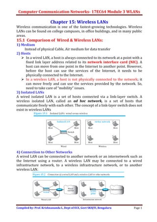
- 1. Computer Communication Networks- 17EC64 Module 3 WLANs Compiled by: Prof. Krishnananda L, Dept of ECE, Govt SKSJTI, Bengaluru Page 1 Chapter 15: Wireless LANs Wireless communication is one of the fastest-growing technologies. Wireless LANs can be found on college campuses, in office buildings, and in many public areas. 15.1 Comparison of Wired & Wireless LANs: 1) Medium Instead of physical Cable, Air medium for data transfer 2) Hosts In a wired LAN, a host is always connected to its network at a point with a fixed link layer address related to its network interface card (NIC). A host can move from one point in the Internet to another point. However, before the host can use the services of the Internet, it needs to be physically connected to the Internet. In a wireless LAN, a host is not physically connected to the network; it can move freely and can use the services provided by the network. So, need to take care of “mobility” issues. 3) Isolated LANs A wired isolated LAN is a set of hosts connected via a link-layer switch. A wireless isolated LAN, called an ad hoc network, is a set of hosts that communicate freely with each other. The concept of a link-layer switch does not exist in wireless LANs 4) Connection to Other Networks A wired LAN can be connected to another network or an internetwork such as the Internet using a router. A wireless LAN may be connected to a wired infrastructure network, to a wireless infrastructure network, or to another wireless LAN.
- 2. Computer Communication Networks- 17EC64 Module 3 WLANs Compiled by: Prof. Krishnananda L, Dept of ECE, Govt SKSJTI, Bengaluru Page 2 When wireless LAN is connected to a wired infrastructure network, the wireless LAN is referred to as an infrastructure network, and the connection to the wired infrastructure (such as the Internet), is done via a device called an Access Point (AP). 5) Migrating from Wired to Wireless Environment: A Wired/Wireless LAN operates only in the bottom two layers of the TCP/IP protocol suite. i.e., if we have a wired LAN connected to the Internet, to move from the wired to wireless environment, we need to change the NICs and replace the link-layer switch with an AP. Now, the link-layer addresses will change, but the network-layer addresses (IP addresses) will remain the same. 15.2 Characteristics of Wireless LANs Attenuation The strength of electromagnetic signals decreases rapidly because the signal disperses in all directions. More severe with battery operated devices. Interference A receiver may receive signals not only from the intended sender, but also from other senders if they are using the same frequency band. Multipath Propagation A receiver may receive more than one signal from the same sender because electromagnetic waves can be reflected back from obstacles. The result is that the receiver receives some signals at different phases (because they travel different paths). Error Errors and error detection are more serious issues in a wireless network than in a wired network. Figure of merit here is SNR (Signal-to-Noise Ratio). If SNR is high, it means that the signal is stronger than the noise, so we may be able to convert the signal to actual data. Another parameter is BER (Bit Error Rate) which is dependent on the channel. A Noisy channel has more BER. For ex, if BER is 10-6, it means 1 bit in 106 bits is in error during txn. So, BER of 10-9 is better than 10-3 . 15.1.3 Access Control In Wired LANs, access method is CSMA/CD. The CSMA/CD algorithm does not work in wireless LANs for the following reasons: 1. To detect a collision, a host needs to send and receive at the same time. Wireless hosts do not have enough power to send and receive at the same time. 2. The hidden station problem prevents collision detection 3. The distance between stations can be large. Signal fading could prevent a station at one end from hearing a collision at the other end. To overcome the above problems, Carrier Sense Multiple Access with Collision Avoidance (CSMA/CA) was designed for wireless LANs.
- 3. Computer Communication Networks- 17EC64 Module 3 WLANs Compiled by: Prof. Krishnananda L, Dept of ECE, Govt SKSJTI, Bengaluru Page 3 Hidden Station Problem: Here, a station may not be aware of another station’s transmission due to some obstacles or range problems; collision may occur but not be detected. Station B has a transmission range shown by the left oval. Station C has a transmission range shown by the right oval. But, stations B and C cannot hear each other, since they are not inside the radio range of each other. Let Station A be in the range of both B and C. Assume that station B is sending data to station A. During that time, station C also has data to send to station A. However, station C is out of B’s range and transmissions from B cannot reach C. Therefore, C thinks the medium is free and sends its data to A, which results in a collision at A. Solution: Handshaking using RTS-CTS signals RTS message from B reaches A, but not C. However, because both B and C are within the range of A, the CTS message (which contains the duration of data transmission from B to A), reaches C. So, Station C knows that some other (hidden) station is using the channel and refrains from transmitting until that duration (called Network Allocation Vector-NAV) is over. 15.2 IEEE Standard for Wireless LANs IEEE has defined the specifications for a wireless LAN, called IEEE 802.11, which covers the physical and data-link layers. Wireless LAN is sometimes referred to as Wi-Fi (Wireless Fidelity).
- 4. Computer Communication Networks- 17EC64 Module 3 WLANs Compiled by: Prof. Krishnananda L, Dept of ECE, Govt SKSJTI, Bengaluru Page 4 15.2.1 Architecture The standard defines two kinds of services: the basic service set (BSS) and the extended service set (ESS). 1) Basic Service Set (BSS): IEEE 802.11 defines the basic service set (BSS) as the building blocks of a wireless LAN. A basic service set is made of stationary or mobile wireless stations and an optional central base station, known as the access point (AP). (Figure 15.4 from book). The BSS without an AP is a stand-alone network and cannot send data to other BSSs. It is called an ad hoc architecture. A BSS with an AP is sometimes referred to as an infrastructure BSS. 2) Extended Service Set (ESS): An extended service set (ESS) is made up of two or more BSSs with APs. The BSSs are connected through a Distribution System (DS), which is a wired or a wireless network. The distribution system connects the APs in the BSSs. When BSSs are connected, the stations within reach of one another can communicate without the use of an AP. Aps are stationary (not moving). Note that a mobile station can belong to more than one BSS at the same time.
- 5. Computer Communication Networks- 17EC64 Module 3 WLANs Compiled by: Prof. Krishnananda L, Dept of ECE, Govt SKSJTI, Bengaluru Page 5 Station Types: IEEE 802.11 defines three types of stations based on their mobility in a wireless LAN: no-transition, BSS-transition, and ESS-transition mobility. A station with no-transition mobility is either stationary (not moving) or moving only inside a BSS. A station with BSS-transition mobility can move from one BSS to another, but the movement is confined inside one ESS. A station with ESS- transition mobility can move from one ESS to another. 15.2.2 MAC Sublayer IEEE 802.11 defines two MAC sublayers: the distributed coordination function (DCF) and point coordination function (PCF). Figure 15.6 shows the relationship between the two MAC sublayers, the LLC sublayer, and the physical layer. 1) Distributed Coordination Function (DCF) DCF is the default implemented in all types of WLAN. i.e., all stations must implement DCF using CSMA/CA access method. (Fig.15.6 from book) DCF Operation: Frame Exchange Fig 15.7 shows the exchange of data and control frames in time.
- 6. Computer Communication Networks- 17EC64 Module 3 WLANs Compiled by: Prof. Krishnananda L, Dept of ECE, Govt SKSJTI, Bengaluru Page 6 1. Before sending a frame, the source station senses the medium by checking the energy level at the carrier frequency. a. The station uses a persistence strategy with backoff until the channel is idle. b. After the channel is found to be idle, the station waits for a period of time called the distributed interframe space (DIFS); then the station sends a control frame called the request to send (RTS). 2. After receiving the RTS and waiting a period of time called the short interframe space (SIFS), the destination station sends a control frame, called the clear to send (CTS), to the source station. This control frame indicates that the destination station is ready to receive data. 3. The source station sends data after waiting an amount of time equal to SIFS. 4. The destination station, after waiting an amount of time equal to SIFS, sends an ACK to show that the frame has been received. Network Allocation Vector (NAV) How do other stations defer sending their data if one station gets access? i.e., how is the collision avoidance aspect considered? This leads to the concept of NAV. When a station sends an RTS frame, it includes the duration of time that it needs to occupy the channel. When destination sends CTS (to all the neighbours of the destination), other stations that are affected by this transmission create a timer called a network allocation vector (NAV) that shows how much time must pass before these stations are allowed to check the channel for idleness. Each time a station accesses the system and sends an RTS frame, other stations start their NAV. In other words, each station, before sensing the physical medium to see if it is idle, first checks its NAV to see if it has expired. 2) Point Coordination Function (PCF) The PCF is an optional access method implemented in an infrastructure network (not in an ad hoc network). It is implemented on top of the DCF and is used mostly for time-sensitive transmission. PCF has a centralized, contention-free polling access method. The AP performs polling for stations that are capable of being polled. The stations are polled one after another, sending any data they have to the AP. To give priority to PCF over DCF, another interframe space, PIFS, has been defined. PIFS (PCF IFS) is shorter than DIFS. This means that if, at the same time, a station wants to use only DCF and an AP wants to use PCF, the AP has priority.
- 7. Computer Communication Networks- 17EC64 Module 3 WLANs Compiled by: Prof. Krishnananda L, Dept of ECE, Govt SKSJTI, Bengaluru Page 7 Due to the priority of PCF over DCF, stations that only use DCF may not gain access to the medium. To prevent this, a repetition interval has been designed to cover both contention-free PCF and contention-based DCF traffic. The repetition interval starts with a special control frame, called a beacon frame. When the stations hear the beacon frame, they start their NAV for the duration of the contention-free period of the repetition interval. Figure 15.8 shows an example of a repetition interval. During the repetition interval, the PC (point controller) can send a poll frame, receive data, send an ACK, receive an ACK, or do any combination of these (802.11 uses piggybacking). At the end of the contention-free period, the PC sends a CF end (contention-free end) frame to allow the contention-based stations to use the medium. 15.3 IEEE 802.11 Frame Format The wireless environment is very noisy, frames may be corrupted which needs retransmission. So, fragmentation (dividing large frame into smaller ones) is necessary. 15.3.1 Frame format The MAC layer frame consists of nine fields, as shown in Fig.
- 8. Computer Communication Networks- 17EC64 Module 3 WLANs Compiled by: Prof. Krishnananda L, Dept of ECE, Govt SKSJTI, Bengaluru Page 8 The fields of IEEE 802.11 frame are: Frame control (FC) - The FC field is 2 bytes long. Table 15.1 describes the subfields. D - This field defines the duration of the transmission that is used to set the value of NAV. Addresses - There are four address fields, each 6 bytes long. The meaning of each address field depends on the value of the To DS and From DS subfields of FC field. Sequence Control (SC)- This field defines a 16-bit value. The first four bits define the fragment number; the last 12 bits define the sequence number, which is same in all fragments. Frame body - This field (0 to 2312 bytes) contains information based on the type and the subtype defined in the FC field. FCS. The FCS field is 4 bytes and contains a CRC-32 error-detection sequence. Table 15.1 Details of FC Filed ( 2 bytes -16 bits) 15.3.2 Frame Types IEEE 802.11 defines 3 types of frames: Management Frames (Type field =00) Management frames are used for the initial communication between stations and access points. Data Frames (Type field =10) Data frames are used for carrying data and control information. Control Frames (Type field=01) Control frames are used for accessing the channel and acknowledging frames. Figure 15.10 shows the format.
- 9. Computer Communication Networks- 17EC64 Module 3 WLANs Compiled by: Prof. Krishnananda L, Dept of ECE, Govt SKSJTI, Bengaluru Page 9 15.3.3 Addressing Mechanism The IEEE 802.11 has defined 4 addresses, defined by two flags (To DS, From DS) in the FC field. The interpretation of the four addresses (address 1 to address 4) in the MAC frame depends on the value of these flags, as shown in Table 15.3. Address 1 is always the address of the next device to which frame is forwarded. Address 2 is always the address of the previous device that the frame has left. Address 3 is the address of the final destination station if it is not defined by address 1 or the original source station if it is not defined by address 2. Case 1: To DS = 0, From DS = 0. The frame is going from one station in a BSS to another without passing through the distribution system. Case 2: To DS = 0, From DS = 1. i.e., the frame is coming from a distribution system. The frame is coming from an AP and going to a station. Address 3 contains the original sender of the frame (in another BSS).
- 10. Computer Communication Networks- 17EC64 Module 3 WLANs Compiled by: Prof. Krishnananda L, Dept of ECE, Govt SKSJTI, Bengaluru Page 10 Case 3: To DS = 1, From DS = 0. i.e., the frame is going to a distribution system. The frame is going from a station to an AP. The ACK is sent to the original station. Address 3 contains the final destination of the frame. Case 4: To DS = 1, From DS = 1. The frame is going from one AP to another AP in a wireless distribution system. 15.4 Exposed Station Problem Here, a station refrains from using a channel when it is, in fact, available. Consider the Fig. shown. Station A is transmitting to station B. Station C has some data to send to station D, which can be sent without interfering with the transmission from A to B. However, station C is exposed to transmission from A; Station C hears the RTS from A and refrains from sending, even though the communication between C and D cannot cause a collision in the zone between A and C, thus wasting the channel capacity. the zone between C and D.
- 11. Computer Communication Networks- 17EC64 Module 3 WLANs Compiled by: Prof. Krishnananda L, Dept of ECE, Govt SKSJTI, Bengaluru Page 11 15.5 IEEE 802.11 Physical Layer There are many PHL standards for WLAN and is evolving. We discuss six specifications, as shown in Table 15.4. All implementations, except the infrared, operate in the industrial, scientific, and medical (ISM) band. ISM defines three unlicensed bands in the three frequency ranges: 902–928 MHz, 2.400–4.835 GHz, and 5.725–5.850 GHz. 15.5.1 IEEE 802.11 FHSS IEEE 802.11 FHSS uses the frequency-hopping spread spectrum (FHSS) method. FHSS uses the 2.400–4.835 GHz ISM band. The band is divided into 79 subbands of 1 MHz (and some guard bands). A pseudorandom number generator selects the hopping sequence. The modulation technique is either two-level FSK or four-level FSK with 1 or 2 bits/baud, which results in a data rate of 1 or 2 Mbps.
- 12. Computer Communication Networks- 17EC64 Module 3 WLANs Compiled by: Prof. Krishnananda L, Dept of ECE, Govt SKSJTI, Bengaluru Page 12 15.5.2 IEEE 802.11 DSSS 802.11 DSSS uses the direct-sequence spread spectrum (DSSS) method. DSSS uses the 2.400–4.835 GHz ISM band. The modulation technique is PSK at 1 Mbaud/s. The system allows 1 or 2 bits/baud (BPSK or QPSK), which results in a data rate of 1 or 2 Mbps. 15.5.3 IEEE 802.11 Infrared 802.11 IR uses infrared light in the range of 800 to 950 nm. The modulation technique is called pulse position modulation (PPM). For a 1-Mbps data rate, a 4-bit sequence is first mapped into a 16-bit sequence in which only one bit is set to 1 and the rest are set to 0. For a 2-Mbps data rate, a 2-bit sequence is first mapped into a 4-bit sequence in which only one bit is set to 1 and the rest are set to 0. The mapped sequences are then converted to optical signals; the presence of light specifies 1, the absence of light specifies 0.
- 13. Computer Communication Networks- 17EC64 Module 3 WLANs Compiled by: Prof. Krishnananda L, Dept of ECE, Govt SKSJTI, Bengaluru Page 13 15.5.4 IEEE 802.11a OFDM 802.11a describes the Orthogonal frequency-division multiplexing (OFDM) method for signal generation in a 5.725–5.850 GHz ISM band. OFDM is similar to FDM, with one major difference: All the subbands are used by one source at a given time. The band is divided into 52 subbands, with 48 subbands for sending 48 groups of bits at a time and 4 subbands for control information. Dividing the band into subbands reduces the effects of interference. If the subbands are used randomly, security can also be increased. OFDM uses PSK and QAM for modulation. The common data rates are 18 Mbps (PSK) and 54 Mbps (QAM). 15.5.5 IEEE 802.11b DSSS IEEE 802.11b describes the High-rate direct-sequence spread spectrum (HRDSSS) method for signal generation in the 2.400–4.835 GHz ISM band. HR- DSSS is similar to DSSS except for the encoding method, which is called complementary code keying (CCK). CCK encodes 4 or 8 bits to one CCK symbol. HR-DSSS defines four data rates: 1, 2, 5.5, and 11 Mbps. The first two use the same modulation techniques as DSSS. The 5.5-Mbps version uses BPSK and transmits at 1.375 Mbaud/s with 4-bit CCK encoding. The 11-Mbps version uses QPSK and transmits at 1.375 Mbps with 8-bit CCK encoding. Fig. shows the modulation technique for this standard. 15.5.6 IEEE 802.11g This new specification defines forward error correction and OFDM using the 2.400–4.835 GHz ISM band. The modulation technique achieves a 22- or 54- Mbps data rate. It is backward-compatible with 802.11b, but the modulation technique is OFDM. 15.5.7 IEEE 802.11n An upgrade to the 802.11 project is called 802.11n (the next generation of wireless LAN). The new standard gives higher bit rate, better throughput & reduced overhead. overhead. The standard uses what is called MIMO (multiple-input multiple-output antenna) to overcome the noise problem in wireless LANs. The idea is that if we can send multiple output signals and receive multiple input signals, noise elimination is better.
- 14. Computer Communication Networks- 17EC64 Module 3 WLANs Compiled by: Prof. Krishnananda L, Dept of ECE, Govt SKSJTI, Bengaluru Page 14 15.6 BLUETOOTH Bluetooth is a wireless LAN technology designed to connect devices such as telephones, notebooks, computers, cameras, printers etc., when they are at a short distance from each other. A Bluetooth LAN is an ad hoc network, i.e., that the network is formed spontaneously; the devices find each other and make a network called a piconet. Bluetooth technology has several applications. Peripheral devices such as a wireless mouse or keyboard can communicate with the computer, monitoring devices can communicate with sensor devices in a small health care center, home security devices can use this to connect different sensors to the main security controller, conference attendees can synchronize their laptop computers at a conference, and so on. Bluetooth was originally started as a project by the Ericsson Company. It is named for Harald Blaatand, the king of Denmark (940-981) who united Denmark and Norway. Blaatand translates to “Bluetooth” in English. Today, Bluetooth technology is the implementation of a protocol defined by the IEEE 802.15 standard. The standard defines a wireless personal- area network (PAN) operable in an area the size of a room or a hall ( 10 to 100m). 15.6.1 Bluetooth Architecture Bluetooth defines two types of networks: piconet and scatternet. 1) Piconets: A Bluetooth basic network is called a piconet, or a small net. A piconet can have up to 8 stations, one of which is called the primary; the rest are called secondaries. All the secondary stations synchronize their clocks and hopping sequence with the primary. The communication between the primary and secondary stations can be one-to-one or one-to-many. Figure 15.17 shows a piconet. Additional secondaries (more than 7) can be in the parked state (cannot take part in communication until it is moved from the parked state to the active state). 2) Scatternet Piconets can be combined to form what is called a scatternet. A secondary station in one piconet can be the primary in another piconet. This station can receive messages from the primary in the first piconet (as a secondary) and, acting as a primary, deliver them to secondaries in the second piconet. A station can be a member of two piconets.
- 15. Computer Communication Networks- 17EC64 Module 3 WLANs Compiled by: Prof. Krishnananda L, Dept of ECE, Govt SKSJTI, Bengaluru Page 15 Bluetooth Devices A Bluetooth device has a built-in short-range radio transceiver. The data rate is 1 Mbps with a 2.4-GHz bandwidth. So, there is a possibility of interference between the IEEE 802.11b wireless LANs and Bluetooth LANs. 15.6.2 Bluetooth Layers Bluetooth uses several layers similar to that of the Internet, but not exactly matching. Fig. 15.19 shows the layers. 15.6.2.1 Radio Layer The Radio Layer is similar to the physical layer of the Internet model. Bluetooth devices are low-power and have a range of 10m. Band Bluetooth uses a 2.4-GHz ISM band divided into 79 channels of 1 MHz each. FHSS Bluetooth uses the frequency-hopping spread spectrum (FHSS) method in the physical layer to avoid interference. Bluetooth “hops” 1600 times per second. A device uses a frequency for only 625 μs (1/1600 s) before it hops to another frequency; So, the dwell time is 625 μs. Modulation To transform bits to a signal, Bluetooth uses a sophisticated version of FSK, called GFSK (FSK with Gaussian bandwidth filtering) GFSK has a carrier frequency. Bit 1 is represented by a frequency deviation above the carrier; bit 0 is represented by a frequency deviation below the carrier. The frequencies are defined according to the following formula for each channel. For example, the first channel uses carrier frequency 2402 MHz (2.402 GHz), and the second channel uses carrier frequency 2403 MHz (2.403 GHz) and so on.
- 16. Computer Communication Networks- 17EC64 Module 3 WLANs Compiled by: Prof. Krishnananda L, Dept of ECE, Govt SKSJTI, Bengaluru Page 16 15.6.2.2 Baseband Layer The baseband layer is equivalent to the MAC sublayer in LANs. The access method is TDMA. The primary and secondary stations communicate with each other using time slots. The length of a time slot is same as dwell time (625 μs). i.e., during the time that one frequency is used, a primary sends a frame to a secondary, or a secondary sends a frame to the primary. Note that the communication is only between the primary and a secondary; secondaries cannot communicate directly with each other. a) TDMA Operation in Bluetooth Baseband Layer Bluetooth uses a form of TDMA that is called TDD-TDMA (Time-division duplex TDMA). TDD-TDMA is a kind of half-duplex communication in which the communication for each direction uses different hops. Single-Secondary Communication The time is divided into slots of 625 μs. The primary uses even-numbered slots (0, 2, 4, . . .); the secondary uses odd-numbered slots (1, 3, 5, . . .). In slot 0, the primary sends and the secondary receives; in slot 1, the secondary sends and the primary receives. The cycle is repeated. (Fig. 15.21) Multiple-Secondary Communication The primary uses the even-numbered slots, but only the addresses secondary responds in the next odd-numbered slot. All secondaries listen on even- numbered slots, but only one secondary sends in any odd-numbered slot. Figure 15.22 shows a scenario. i. In slot 0, the primary sends a frame to secondary 1. ii. In slot 1, only secondary 1 sends a frame to the primary because the previous frame was addressed to secondary 1; other secondaries are silent. iii. In slot 2, the primary sends a frame to secondary 2. iv. In slot 3, only secondary 2 sends a frame to the primary because the previous frame was addressed to secondary 2; other secondaries are silent. v. The cycle continues.
- 17. Computer Communication Networks- 17EC64 Module 3 WLANs Compiled by: Prof. Krishnananda L, Dept of ECE, Govt SKSJTI, Bengaluru Page 17 b) Type of Links in Baseband Layer Two types of links can be created between a primary and a secondary: SCO links and ACL links. i) SCO: Synchronous Connection-Oriented (SCO) link is used when avoiding latency (delay in data delivery) is more important than integrity (error-free delivery). A physical link is created between the primary and a secondary by reserving specific slots at regular intervals. The basic unit of connection is two slots, one for each direction. If a packet is damaged, it is NOT retransmitted. SCO is used for real-time audio where avoiding delay is all-important. A secondary can create up to 3 SCO links with the primary. ii) ACL: Asynchronous Connectionless link (ACL) is used when data integrity is more important than avoiding latency. Here, if the frame is corrupted, it is retransmitted. A secondary returns an ACL frame in the available odd-numbered slot if the previous slot has been addressed to it. ACL can use one, three, or more slots and can achieve a maximum data rate of 721 kbps. c) Frame Format in Baseband Layer A frame in the baseband layer can be: one-slot, three-slot, or five-slot. A slot is 625 μs. But, 259 μs is needed for hopping and control mechanisms. So, a one-slot frame can last only 625−259=366 μs. With a 1-MHz bandwidth and 1 bit/Hz, the size of a one-slot frame is 366 bits. A 3-slot frame occupies three slots. However, since 259 μs is used for hopping, the length of the frame is 3 × 625 − 259 = 1616 μs or 1616 bits. A device that uses a 3-slot frame remains at the same hop/ same carrier frequency for 3 slots. The hop number for each frame is equal to the first slot of the frame.
- 18. Computer Communication Networks- 17EC64 Module 3 WLANs Compiled by: Prof. Krishnananda L, Dept of ECE, Govt SKSJTI, Bengaluru Page 18 A 5-slot frame also uses 259 bits for hopping, which means that the length of the frame is 5 × 625 − 259 = 2866 bits. Figure 15.23 shows the format of the three frame types. Each field is described below: ❑ Access code. This 72-bit field contains synchronization bits and the ID of the primary to distinguish the frame of one piconet from that of another. ❑ Header. This 54-bit field is a repeated 18-bit pattern. Each pattern has the following subfields: i. Address – (3 bits) can define up to 7 secondaries (1 to 7). If the address is zero, it is used for broadcast communication from the primary to all secondaries. ii. Type – (4 bits) defines the type of data coming from the upper layers. iii. F – (1 bit) for flow control. When set (1), it indicates that the device is unable to receive more frames (buffer is full). iv. A – (1 bit) This field is for ACK. Bluetooth uses Stop-and-Wait ARQ;. v. S – (1 bit) This field holds a sequence number of the frame. vi. HEC – (8 bits). The 8-bit Header Error Correction subfield is a checksum to detect errors in each 18-bit header section. The header has three identical 18-bit sections. The receiver compares these three sections, bit by bit. If each of the corresponding bits is the same, the bit is accepted. There is no retransmission in this sublayer. ❑ Payload. This subfield can be 0 to 2740 bits long. It contains data or control information coming from the upper layers. 15.6.2.3 L2CAP Layer The Logical Link Control and Adaptation Protocol, or L2CAP is used for data exchange on an ACL link; SCO channels do not use L2CAP. Figure 15.20 shows the format of the data packet at this level.
- 19. Computer Communication Networks- 17EC64 Module 3 WLANs Compiled by: Prof. Krishnananda L, Dept of ECE, Govt SKSJTI, Bengaluru Page 19 The 16-bit length field defines the size of the data coming from the upper layers. Data can be up to 65,535 bytes. The channel ID (CID) defines a unique identifier for the virtual channel created at this level. The L2CAP has specific functions: multiplexing, segmentation and reassembly, qualityof service (QoS), and group management. a) Multiplexing The L2CAP can do multiplexing. At the sender site, it accepts data from one of the upper-layer protocols, frames them, and delivers them to the baseband layer. At the receiver site, it accepts a frame from the baseband layer, extracts the data, and delivers them to the appropriate protocol layer b) Segmentation and Reassembly The maximum size of the payload field in the baseband layer is 2774 bits, or 343 bytes (including 4 bytes to define the packet and packet length). So, the size of the packet that can arrive from an upper layer can only be 339 bytes. However, if data from upper layer is more than this, the L2CAP divides these large packets into segments and adds extra information to define the location of the segments in the original packet. The L2CAP segments the packets at the source and reassembles them at the destination. c) QoS Bluetooth allows the stations to define a quality-of-service level. d) Group Management Allow devices to create a type of logical addressing between themselves. This is similar to multicasting. For ex, 2 or 3 secondary devices can be part of a multicast group to receive data from the primary.