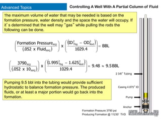
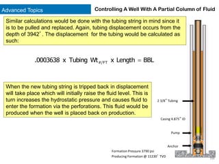
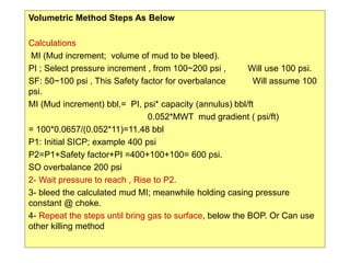
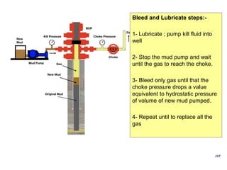
Completion and Workover Well Control
Table of Contents
2
Well Data 6
Reasons for Workovers –Repair Mechanical Damage 7
Reasons for Workovers –Repair Formation Damage 8
Reasons For Workovers –Reservoir Stimulation 9
Reasons For Workovers –Hydraulic Fracturing 10
Reasons For Workovers –Completing a Previously Non-Produced Reservoir 13
Reasons For Workovers –Recompleting Multiple Reservoirs 15
Reasons For Workovers –Water Coning 16
Reasons For Workovers –Water Intrusion 17
Reasons For Workovers –Gas Intrustion 18
Reasons For Workovers –Unwanted Water and Gas Production 19
Reasons For Workovers –Repair Failed Cement 20
Reasons For Workovers –Installing a Velocity String 21
Reasons For Workovers –Replacement of the Tubing 22
Table of Contents
3
Completion Types –Open Hole or “Barefoot” Completion 23
Completion Types –Single & Dual String Flowing Well 24
Completion Types –Gravel Pack 25
Completion Types –Gas Lift 26
Completion Types –Sucker Rod Pump 28
Completion Types –Electrical Submersible Pump 29
Completion Types –Plunger Lift 30
Differences Between Workovers and Drilling 31
Hydrostatics 35
Estimating Formation Pressure 37
Brines 40
Friction Pressure 49
Killing a Producing Well: Non-Circulating Techniques –Lubrication and Bleeding 55
Killing a Producing Well: Non-Circulating Techniques –Bullheading 68
Table of Contents
4
Holes in the Tubing 76
Gaining Tubing to Casing Communication 84
Differential Pressure 90
Estimating Differential Pressure 91
Initial Circulation 94
Initial Circulation Manifolding 95
Causes of Kicks 103
Warning Signs of Kicks 106
Shut In Procedures 108
Shut In Pressures 110
Vital Information 113
Circulating Kill Methods 114
Kill Methods 116
Basic Kill Procedure – Wait and Weight 117
Table of Contents
5
Advanced Topics 141
Advanced Topics –Friction Pressure Estimation for Workover Fluids 142
Advanced Topics –Controlling a Well With a Partial Column of Fluid 146
Volumetric Method; Lubricate and Bleed 151
Well Data
6
Completed Well
5 ½” Production Casing, 4.892” ID
SCSSV @ 320’
Sliding Sleeve w/X Nipple
@ 14691’ MD
Packer @ 14702’ MD
Gas Lift Mandrel
@ 3103’ MD
XN Nipple @ 14712’ MD
3 ½” Tbg, 2.875” ID
15000 psi Burst
Perfs @ 14721-14808’ MD
12580-12688’ TVD
Gas Lift Mandrel
@ 9827’ MD
Gas Lift Mandrel
@ 13808’ MD
Rathole 4.892” ID x 288’ Length
PBTD 15000’ MD
Reasons For Workovers
7
Repair Mechanical Damage
Tree Failure
Subsurface Safety
Valve Failure
Hole/s In The
Tubing
Failed Sliding Sleeve
Packer Leak
Seal Assembly Leak
Plugged Perfs
Repair Faulty Gas Lift
Valve or Dummy
Production takes a heavy toll on equipment. Shown at
right are some of the most common well-related
equipment that can wear, require maintenance, and in
some cases, replacement:
High production rates lead to internal erosion of the
tubing and bores of safety valves, nipples, sliding
sleeves, gas lift mandrels, submersible pumps, etc.
Extreme production rates can also damage the
producing zone directly adjacent to the wellbore.
Sealing elements deteriorate over time.
Metallic failures caused by corrosive fluids such as
carbon dioxide and hydrogen sulfide.
Reasons For Workovers
8
Repair Formation Damage
Filtrate invasion usually occurs while the well is drilled. Drilling mud use to drill
wells contains solids, drilled up solids and commercially added solids. These
solids are suspended in the fluid while it is circulated. Formation invasion
takes place when the mud comes into contact with a porous and permeable
formation and the pressure in the hole at the depth of the formation is greater
than the naturally occurring formation pressure. Excessive filtration invasion
can reduce the permeability of a formation and inhibit production.
Reasons For Workovers
9
Repair Formation Damage
In a similar fashion to drilling solids, cement can invade a formation when casing is
cemented into place. And like drilling solids, cement invasion can reduce formation
permeability and productivity potential.
Reasons For Workovers
10
Repair Formation Damage
Pipe Dope
Other sources of formation damage occur during production, completions and workovers. The worst damage
is caused by pipe dope. Pipe dope, while necessary, is commonly used to excess. This excess finds its way
out of the workstring through fluid circulation and into producing formations where it decreases permeability.
Pipe dope, once deposited, is virtually impossible to remove, so the damage is permanent.
Perforator Debris
When a perforator goes off it pushes various types of chemical and metallic debris into the producing
formation. This debris, if not flowed out of the formation, can remain and decrease near-wellbore permeability.
Because of this, some wells are perforated underbalanced to initiate an immediate flow into the well following
perforation.
Dirty Completion Fluid
The fluid of choice in most completions and workovers is a solids-free brine. Brines can be mixed to supply
sufficient density to control even the most extreme formation pressure – Calcium Bromide/Zinc Bromide can
be mixed to a stable density of 20.2 ppg. And this is accomplished without solids, which can cause formation
damage. It defies logic to use a solids free fluid and then mix and store it in dirty pits and fail to filter it when it
is circulated through the well.
Iron Sulfide Scale
Iron sulfide, a compound created from the chemical combination of iron and sulfur, collects on the inside of the
tubing string and can be dislodged during trips into and out of the hole. Naturally, the bulk of this debris
remains in the well and is circulated around by the workover fluid, but some does find its way into the
producing formation and can reduce permeability.
Reasons For Workovers
11
Reservoir Stimulation
Often times an acid job is conducted to
enhance lost permeability or dissolve scale
or other precipitates in an effort to regain
production.
This can be done by bullheading acid into
the perforations, or placing the acid adjacent
to the perforations with coiled tubing or
small jointed tubing conveyed by a small
workover rig or pulling unit.
Reasons For Workovers
12
Reservoir Stimulation – Hydraulic Fracturing
Frac jobs are done on some wells during the initial completion
and may also occur during a workover. This procedure is
conducted on hydrocarbon-bearing formations that lack natural
permeability sufficient to allow the well to flow. Water,
surfactants, inhibitors and sand is pumped at high rates and
pressure which create minute fractures allowing the escape of
oil and gas. The sand serves as a proppant which hold the
fractures open.
Understanding The Basics: 13
Completing A Previously Non-Produced Reservoir
Completing a new reservoir can be as simple
as plugging off a depleted zone and making
communication with a previously perforated but
not produced formation.
First, the depleted zone has to be isolated. This
can be done by installing a wireline or coiled
tubing-set positive plug.
After the plug has been set and successfully
tested, a sliding sleeve adjacent to another
previously perforated producing interval can be
opened, by either wireline or coiled tubing,
allowing production to take place.
Reasons For Workovers
Completion/Workover Well Control: 14
Completing A Previously Non-Produced Reservoir
In this completion a previously non-produced zone is
brought into production:
A wireline-set positive plug is set to isolate a lower depleted
zone
The tubing is cut just above the packer, the tubing is
removed and a cement plug is placed above the tubing stub
and packer
The old tubing string is recovered
A new string of tubing is run along with a packer
The new zone is perforated and the well is cleaned up and
brought on to production
Reasons For Workovers
15
Re-Completing Multiple Reservoirs
A dual completion lends itself where multiple
reservoirs are perforated and it’s undesirable or
against regulations to co-mingle produced fluids.
The reservoirs are separated by a dual production
packer and a single production/isolation packer.
A dual completion presents special problems with
respect to well control where formation pressures
can be vastly different, with one formation
constantly taking fluid and the other always on the
verge of coming in.
Reasons For Workovers
16
Water Coning
Water coning occurs due to excessive
production. The gas or oil is being produced at
such a rate that formation water residing at the
bottom of the producing formation is literally
“sucked” up into the tubing and flows to the
surface.
Remedial action is usually a decrease in the
production rate but this rarely has a great effect.
Once the path has been opened for water
production it’s next to impossible to decrease
the water production. If the well is shut-in for an
extended period of time the water may begin to
settle back into place, but more often, the
production rate is decreased and the water is
dealt with at the surface.
OIL
WATER
Reasons For Workovers
17
Water Intrusion
OIL
WATER
This is not to be confused with water coning.
Water can, and usually will be produced as oil
and/or gas is depleted. If sufficient hydrocarbons
have been produced the water production will be
tolerated as an eventual by-product of
production. However in some cases, the lower
perforations can be cement squeezed to
minimize the volume of water being produced.
This is especially so if theres no present
economical means of properly disposing of the
water.
If the producing formation is water-driven, the
water can be captured and injected into the
formation by means of an injection well.
Reasons For Workovers
18
Gas Intrusion
GAS
OIL
The gas cap of a gas cap driven reservoir
expands as production occurs. Eventually the gas
intrudes on the perforations and becomes part of
the produced fluids and will be noticed at the
surface.
In some cases the gas is produced along with the
oil but in others, efforts are made to restrict gas
production. This can be done with a cement
squeeze across selected perforations.
Reasons For Workovers
19
Unwanted Water/Gas Production
Squeezing The Perfs
The usual remedy for unwanted gas or
water production is to squeeze the
perforations with cement in hopes that the
“watered-out” perforations will be plugged
and the water production decreased.
The process entails identifying the affected
perforations then running and setting a
squeeze or straddle packer just above or
adjacent to the affected perforations.
Cement is then pumped down the
workstring and into the perforations.
Reasons For Workovers
20
Repair Failed Cement
Cement that hasn’t cured properly or is subject to the
friction created by production can begin to fail. It
usually is first noticed in the choke body of the
Christmas tree where it partially or totally plugs the
production choke.
Not only can this damage expensive production
equipment but the presence of cement in production
equipment should signal the need to make repairs.
A failed cement job can lead to communication with
other formations and eventual premature casing
failure. Remedial action is usually in the form of a
cement squeeze across the perforations and re-
perforation.
Reasons For Workovers
21
Casing
Production Tbg
Velocity String
Installing A Velocity String
A velocity string is a small diameter tubular installed
in a well for the purposes of production
enhancement or delivering measured amounts of
chemical treatment. The string can be run inside
existing tubing or strapped along side it. Coiled
tubing units are common conveyors of velocity
strings however they can also be installed and
serviced using conventional workover rigs and
pulling units.
Casing
Production Tbg
Velocity String
Reasons For Workovers
22
Replacement Of The Tubing
The very act of production exerts wear and tear on
production tubulars. Erosional forces and corrosion take
a heavy toll. The tubing can develop holes or slits, or
may even part in places. Eventually it has to be
replaced.
This can be done with a snubbing unit without killing the
well or can be done with a conventional workover rig
after the well is killed.
Completion Types
23
Open Hole or “Barefoot” Completion
A barefoot completion is one in which no packer is installed
and production takes place via tubing and casing. This type
of completion is generally placed in a well in which the
producing formation is relatively competent like a limestone
or very competent sandstone.
There are advantages to this type of completion. It’s simple,
inexpensive, and fast to install and maintain. It also
provides for more formation surface area to be exposed to
the wellbore. No perforation is required but prior to
production a frac job is usually done. And an open hole
completion lends itself to deepening if so desired.
There are some disadvantages to the barefoot completion.
Initial well killing can be difficult because both sides of the
well are live and can have dissimilar fluids. Additionally, fluid
loss is a definite problem while working the well over. This
type of completion is not recommended where the
producing formation is layered and has varying
permeabilities within the layers.
Completion Types
24
Single & Dual String Flowing Well
Shown here are two very
common completions for
formations that will flow.
Given the simplicity of the
single completion, well control
as well as other work to be
performed on the well is
noticeably easier than a dual
completion.
A dual completion does
present a host of special
problems most of which are
related to two open formations
during the completion and
subsequent workovers.
Completion Types
25
Gravel Pack
A gravel pack completion is used where the
producing formation lacks sufficient consolidation
to withstand the friction caused by fluid flow from
the formation to the wellbore.
A slurry of “sand” and viscous liquid is pumped
down the workstring and into the annular space
between the casing and the screen until it is
filled, or “sands out.” Excess sand slurry
remaining in the workstring is reversed out.
Another similar operation, known as a frac pack,
involves pumping the sand slurry at high rates
forcing the mixture far out into the producing
formation somewhat like a frac job.
Gravel Pack
Packer
Screen
Sump Packer
Completion Types
26
Gas Lift
Gas and Formation Fluids
Gas injected into
casing
A gas lift completion is used to enhance the
production of formation liquids. In most cases
this liquid is oil but this type of completion lends
itself to gas wells that produce large volumes of
water. Naturally, a constant source of gas is
required.
Gas is injected into the casing and enters the
tubing, either intermittently or on a continual
basis, through gas lift valves. The gas enters the
column of produced liquid and “lightens” the
column allowing the residual formation pressure
to flow the column to the surface where the
liquids and gas can be separated.
Completion Types
27
Gas Lift A typical gas lift installation.
Completion Types
28
Sucker Rod Pump
On the up stroke oil is lifted by the
pump and seal assembly. The
pump check valve is off-seat, as is
the standing valve. On the down
stroke the standing valve and
pump check valve go on-seat as
the pump moves through the
column of oil to begin another up
stroke.
The sucker rod pump – the
iconic symbol of the oil
industry has been used
successfully for decades to
produce oil from low pressure
formations. Its design and
working principal are simple.
As seen at right, oil is brought
to the surface by means of a
moveable pump reciprocated
by the pumping unit, sucker
rods, and the two ball-type
check valves, one in the
pump and the other in the
standing valve.
The efficiency of the system does suffer if the producing formation
also contains a fair amount of free gas which can cause the pump
to “gas lock.” And due to its mechanical nature, rods, the pump,
and tubing need to be changed periodically.
Pump
Standing
Valve
Completion Types
29
Electric Submersible Pump
The Electric Submersible Pump is an artificial lift
device that relies on electricity to power a downhole
centrifugal pump to produce oil or in some cases,
excessive water production in a gas well.
The pump assembly is made up to the production
string and is comprised of a few sections (from
bottom up):
• Motor and monitor with the electrical cable
strapped to the tubing
• The seal section and in some pumps, a gas
separator
• Pump
The electrical cable finally terminates in a special
connection in the tubing hanger. A cable runs from
there to a controller on the surface
Courtesy of Weatherford
Completion Types
30
Plunger Lift
A plunger lift system is used to remove excess
produced water thus allowing gas production
to take place.
Water accumulates at the bottom of the well
while the well is shut-in and wellbore pressure
builds. At a pre-determined pressure a valve
on the flowline opens thus creating a
differential pressure across the plunger,
causing it to rise to surface and removing the
water ahead of it.
The plunger is held in the lubricator until gas
production wanes and surface pressure
declines. The plunger is then released and it
falls to the bottom of the well and contacts the
bumper.
This process cycles several times a day.
1000
2000
3000
0
500
1500 2500
3500
Differences Between Workovers & Drilling
31
Known Source of Hydrocarbons
The formation or formations being worked on are a known source of hydrocarbons
and hydrocarbons have been brought to the surface. Therefore, there is a definite
potential for a blowout and/or fire.
Trips
“If there’s one thing you’re gonna do during a workover, it’s trippin’ pipe. Or so the
saying goes. But a workover is usually characterized by extensive tripping. And with
trips comes the potential for swabbing in the well and/or losing copious volumes of
fluid to the producing formation. With excessive fluid loss there is the possibility of the
well coming in.
Various Tools and Services
In many completions and/or workovers, many different types of tools along with
service personnel are used which can complicate not only the workover but a kill
procedure as well.
Differences Between Workovers & Drilling
32
Wellbore Volume
This can’t be overly stressed. The volume in a well that is being worked over is
a fraction of what it was when it was drilled. Because of that, things will happen
faster. Volumes can and will be displaced faster which mean surface pressures will
change faster making pressure management all the more difficult.
Fluids
Workover brine behaves very differently than drilling mud. While it does have
density, that density can be severely affected by downhole temperature.
Drilling mud has viscosity, workover fluid, containing no solids has very little viscosity.
Drilling mud has a yield point which slows the fall of solids. Workover brines have no
yield point.
Drilling mud, especially synthetic-based oil mud can be somewhat expensive, but that
expense pales in comparison to the costs of a triple density workover brine.
Differences Between Workovers & Drilling
33
Gas Migration
While gas migration can be an issue while a well is being drilled, it’s pretty much a
“given” during a completion or workover. Workover fluids lack the viscosity that
drilling mud has which minimizes or in some cases, prohibits gas migration.
Gas migration can be especially troublesome when attempting to determine stabilized
Shut-In Tubing Pressure and Shut-In Casing Pressure.
Well Killing
In many cases, before the workover can begin or before the rig or workover unit is
moved on location, the well must be killed. This may have to be accomplished by
some seemingly unorthodox methods; some of which involves circulation and some
that don’t.
Formation Fluid
Formation fluids may be in both the tubing and casing at the same time.
Differences Between Workovers & Drilling
34
Tubing Kick
All too common in workovers and completions are tubing kicks. This usually occurs
just prior to or after a trip.
Condition Of The Tubulars
Many workovers are conducted because of tubing leaks or is parted. Other workovers
are conduced to repair casing failures. In the case of casing failures, formation
pressures can communicate to various casing strings which can make for very
complicated workovers and pressure control.
Hydrostatics
35
Produced fluids
In some cases it may be necessary to estimate the hydrostatic pressure of produced
fluids. Produced gas and water are measured in gradient but crude
oil is different.
Produced Gas
PSI
Length
Column
Gradient Vertical
FT
/
PSI =

Produced Water
PSI
Length
Column
Gradient Vertical
FT
/
PSI =

Estimating the hydrostatic pressure of crude oil is a bit different. The density of oil is
measured in API gravity (API°), the scale being 10 to 60. Crude oil is also very
temperature sensitive. Because of this the density of oil is measured with an API
hydrometer rather than a standard mud balance. The hydrometer not only measures
the density but the temperature as well. But since the hydrometer is calibrated to be
accurate at 60° F, a mathematical correction must be made based on the observed
density and temperature.
Hydrostatics
36
Crude Oil
To determine the hydrostatic pressure of a column of crude oil perform the following:
Observed APIGravity -
Observed Temp - 60
( )
10
æ
è
ç
ö
ø
÷ = APICorrected
141.5
131.5 + APICorrected
( )
æ
è
ç
ö
ø
÷ x .433PSI/Ft x Column LengthVertical = HydrostaticPSI
For example:
Calculate the hydrostatic pressure for this column of crude oil.
Oil Gravity 31.2°
Observed Temperature 112° F
Column Length 6862’
Hydrostatic Pressure = ________ psi
_______Observed API -
Observed Temp - 60
( )
10
æ
è
ç
ö
ø
÷ = _______Corrected API
141.5
131.5 + ________Corrected API
( )
æ
è
ç
ö
ø
÷ x .433PSI/Ft x ________Column Length' = _______PSI
Estimating Formation Pressure
37
In some cases well files may not indicate the formation
pressure of the well to be worked over, but based on
production records and a little wireline work to find fluid
levels, a useable estimate can be made.
Use the formulas presented on the previous pages and
the information given to estimate formation pressure and
kill weight fluid.
Wellbore Fluids
Gas – 0’ to 2182’, .135 psi/ft gradient
Oil - 2182’ to the top perfs @ 14889’, 38.3° API
and temperature of 117° F.
SITP is 5420 psi
Determine the formation pressure in PSI and PPG and a kill
fluid density that will overbalance the formation by .3 ppg.
Estimating Formation Pressure
38
PSI
Vertical
FT
/
PSI ________
Length
________
x
______ =
Gas Hydrostatic Pressure
Oil Hydrostatic Pressure
________Gravity -
- 60
( )
10
æ
è
ç
ö
ø
÷ = ________APICorrected
( ) PSI
Feet
Ft
/
PSI ________
________
x
433
.
x
________
5
.
131
5
.
141
=








+
Formation PressurePSI
PSI
PSI
PSI
PSI ________
______
HP
Oil
______
HP
Gas
______
SITP =
+
+
Estimating Formation Pressure
39
Formation PressurePPG
PPG
Feet
PSI ________
_______
.052
________ =


Kill Fluid DensityPPG
PPG
PPG
PPG ________
______
e
Overbalanc
_______
Pressure
Formation =
+
Brines
40
General Characteristics
Since solids can decrease formation permeability,
brines, which are solids-free fluids, are commonly
used in completions and workovers. They can be
mixed to stable densities greater than 20 ppg.
Brines are subject to the effects of temperature
resulting in a decrease in brine density as
temperature increases. The density decrease can
be estimated and compensated for on location.
Brine density should not be measured with a
conventional mud balance but rather a brine
hydrometer which measures both specific gravity and
temperature.
Brines also have the ability to crystallize, not only on the surface (freeze point) but in the
wellbore as well so temperature is a critical factor is formulating a brine and maintaining brine
stability. The following few pages are dedicated to determining the effect of temperature on the
brine density and how we can compensated for this.
Brine Hydrometer Kit
Courtesy of Fann
Brines
41
Brine PPG SG
Potassium Chloride 9.7 1.1645
Magnesium Chloride 9.9 1.1885
Sodium Chloride/Potassium Chloride 10.0 1.2005
Calcium Nitrate 10.5 1.2605
Sodium Formate 11.1 1.3325
Potassium Bromide & Potassium Bromide/Potassium Chloride 11.5 1.3806
Calcium Chloride 11.7 1.4046
Potassium Carbonate 12.8 1.5366
Sodium Bromide/Sodium Chloride & Sodium Bromide 12.7 1.5246
Potassium Formate 13.3 1.5966
Calcium Bromide & Calcium Bromide/Calcium Chloride 15.4 1.8487
Cesium Formate/Cesium Acetate 19.7 2.3649
Zinc Bromide/Calcium Bromide & Zinc Bromide 20.5 2.4610
The table below lists the more common workover brines used and indicates their
maximum stable densities.
Maximum Density
Brines
42
Temperature Sensitivity – Volume Increase
As already mentioned, brine density decreases with temperature and with that there
is a corresponding increase in volume. The following can be used to estimate the
volume increase due to thermal expansion.
STEP 1 Volume Change Factor
The Volume Change Factor can be determined from the chart on the following
page.
STEP 2 Resulting Volume
BBL
Factor
Change
Volume
x
Volume
Brine
Prepared BBL =
Brines
43
50
50 100 150 200 250 300
1.0
1.01
1.02
1.03
1.04
1.05
1.06
1.07
Fluid Temp F°
Volume
Change
Factor
NaCl, KCl, CaCl
ZnCl2, CaCl
CaCl2 & CaBr
Temperature Sensitivity
Volume Change Factor
Find the average fluid temperature on
the horizontal axis. Intersect the line
based on the brine in use. Read to
the left to determine the volume
change factor.
Brines
44
Brine Selection
The selection of a brine is based on many factors:
Density and crystallization point – Crystallization can occur because of extremes in
temperature (high and low) which results in salt precipitating from the liquid and being
deposited in surface lines and vessels along with downhole. Density can be decreased
with downhole crystallization.
Chemical compatibility with the producing formation and formation fluids – Shale
swelling is possible in some cases and iron compounds can precipitate from iron
contamination in the brine. Emulsions can be created from formation fluids - brines
contact. Scales can be formed which are deposited on tubulars and in the formation.
Corrosion – Brines are corrosive to varying extents based on density and chemical
composition. Suffice it to say that brines should not be stored or used in steel pits as
corrosion is bound to happen, and the by-products of corrosion would get pumped
downhole increasing the risk of formation damage.
Cost – Brines are not cheap with dual and triple density brines renting for hundreds of
dollars per bbl.
Brines
45
Brine & HSE
Skin Exposure
All brines can have adverse effects when contacting bare skin and the severity of the
reaction usually corresponds to the brine density and acidity. Latent exposure can
take place from wet clothing.
Exposed skin should be washed thoroughly with soap and water and medical
attention sought if there is persistent irritation or any discoloration of the skin.
Eyes and Mucous Membranes
Always wear proper goggles or a full face shield.
Immediate irritation will be noticed. Wash the affected area profusely with water for at
least 15-20 minutes and then seek professional medical attention. Make sure to
inform medical personnel of the type of brine that contaminated the area.
Accidental Ingestion
Severe damage to the mucous membranes of the digestive tract are possible along
with chemical poisoning. Induce vomiting only if the victim is fully conscious. Seek
immediate professional medical attention.
Brines
46
Brine & HSE
PPE
Eyes
Use chemical splash goggles or an approved face shield. Basic safety glasses are not
enough because they lack adequate side shielding of the eyes.
Hands and Arms
Always wear long-armed plastic or rubber gloves as the base gloves. Cotton gloves can
be worn over the plastic gloves to minimize tearing.
It’s also advised to use barrier creams containing lanolin and/or glycerine. The barrier
cream should be applied before donning gloves. And remember: Barrier creams do not
take the place of gloves.
Feet
Steel toe rubber boots are a must – preferably those with generous sole tread to prevent
slips and falls. Leather boots are destroyed (stiffen and eventually shrink several sizes)
when saturated with brines. Although there are some “rig remedies” for treating leather
boots that have been saturated with brines, but seldom are these successful and require
that the boots not be worn for an extended period of time.
Brines
47
Body
Protect the trunk of the body with an apron or slicker suit when handling sacks of
brine or anytime extended periods of time are spent near brine working or storage
pits.
Wear a slicker suit or Hazmat suit when on the floor tripping pipe along with the
previously mentioned hand and eye protection. Additionally, wear a disposable
mist/dust respirator when working near a pit of brine for an extended period of time
and anytime when mixing dry brine additives.
Brine & HSE
Rig Preparation
Pits and Surface Lines
Spend at least 24 hours preparing the rig for brine use. The primary purpose of using
a brine is to prevent solids invasion of a producing formation so it’s pointless to use a
brine if the rig components that will come in contact with the brine are not thoroughly
cleaned. Simply jetting a pit is not sufficient. All pits, pumps, and surface lines should
be cleaned internally with soap and water, rinsed, and then allowed to dry. If possible,
do not use steel pits.
Brines
48
Rig Preparation
Make sure that pits can be covered to prevent dilution of the brine by rain or
atmospheric humidity. The pits should be initially filled with clean, fresh water to
check for leaks and the gates should be tested for leaks as well.
If rubber hoses are to be used they should be compatible with brines. Advise service
personnel of the type of brine to be used to ensure their equipment is compatible.
It’s also best to have the brine as the only fluid onboard the rig to prevent
contamination of the brine by mud or mud products.
Packer Fluids
Packer fluids, normally brines, placed between the tubing and casing are inhibited
with chemicals to reduce corrosion. They are sometimes weighted up to control
pressure in the annulus. They are not always weighted to kill fluid density.
Friction Pressure
49
Estimating Friction Pressure
In Chapter 1 a “down and dirty” method of estimating friction pressure was presented.
The same can be done with brines but the ratio is a bit different. For completion fluids use
a 90:10 ratio meaning about 90% of observed pump pressure is created in the workstring
and 10% being created in the annulus. At the end of this chapter is a mathematical
procedure that can be used to more accurately estimate friction pressure created when
using completion fluids.
Information required to accurately estimate completion fluid friction pressure and
associated ECD is:
Fluid Density – measured with a brine hydrometer
Fluid Viscosity – test performed by fluid specialist
Wellbore Geometry – ID’s and OD’s of the entire wellbore – restrictions associated with
specialty tools, tubing nipples, etc., can result in observed friction exceeding the
calculated friction pressure
Pump Rate
Flow Direction – normal versus reverse circulation
Friction Pressure
50
Normal and Reverse Circulation
Earlier in the text the properties of a solids-laden drilling mud that aid in cuttings
transport was discussed. Three properties mentioned were:
Density
Yield Point
Gel Strength
Brines, purposely lacking solids, do not, by design, possess a yield point or gel
strength. However, polymers can be added to provide gel strength which can aid in
particle transport and suspension.
Because of the minimal “thickness” of workover fluids, both normal and reverse
circulation is used to remove solids from wellbores. The next few pages are devoted
to friction created while working over or completing a well and the impact that friction
has on bottom hole pressure.
Friction Pressure
51
Normal and Reverse Circulation
Consider this: the well at right is being
circulated normally – down the workstring and
back up the annulus. The pump pressure
indicates the total friction pressure being
experienced by the pump.
1000
2000
3000
0
500
1500 2500
3500
Pump Rate = 80spm
Based on the 90:10 ratio approximately 900 psi is being created in the
workstring and 100 psi in the annulus. So BHP has increased by the
annular friction, or in this case, 100 psi and an ECD could be calculated
based on this.
13.5 ppg fluid
15000 feet
PPG
PPG
ft
psi 13.62
13.5
)
15000
.052
(100 =
+


Friction Pressure
52
Normal and Reverse Circulation
Reverse circulation is now being
employed, the pump is brought to the
same rate as before, and again the pump
gauge is measuring total friction
pressure.
1000
2000
3000
0
500
1500 2500
3500
Pump Rate = 80spm
But in this case the BHP has increased significantly. The
workstring, being the “return line” is now downstream of the
perforations and the workstring friction is being imposed at the
bottom of the hole. In theory, the ECD would be:
13.5 ppg fluid
15000 feet
PPG
PPG
ft
psi 14.65
13.5
)
15000
.052
(900 =
+


Friction Pressure
53
1000
2000
3000
0
500
1500 2500
3500
Pump Rate = 80spm
Therefore, it’s unlikely the pump pressure would return to the
pressure observed during normal circulation. Some fluid would
be pumped into the perforations because of the elevated BHP.
Expensive workover fluid be lost but the possibility of formation
contamination of solids is possible along with formation failure.
The point to be taken is not to condemn reverse circulation
but a careful “look” at the potential impact on BHP should
be done before the surface plumbing is adjusted and
reverse circulation conducted.
Normal and Reverse Circulation
From the previous page it becomes clear
that there is an inherent “drawback” to
reverse circulating – BHP increases
substantially.
Friction Pressure
54
Slow Pump Rates
Slow pump rates that are taken while a well is being drilled represent circulating system friction pressure at the
time they are taken. The same is true during a completion or workover but in a completion or workover, slow
pump rates accuracy are much more reliable.
While a well is being drilled all of the items that affect friction pressure are constantly changing: system
geometry, fluid properties, and circulating rate. And because of this it’s imperative the driller be very diligent
about slow pump rates.
However, during the course of a completion or workover, the system geometry usually stays consistent and
the fluid properties don’t change much. Therefore, it’s a good idea to take slow pump rates once the well is
dead and full of kill fluid.
It’s recommended that at least 3 slow pump rates be taken and there’s nothing wrong with 4 or 5. And like
slow pump rates in drilling, record the rate (spm, bpm, gpm) and the corresponding pressures.
RATE PSI BPM GPM
50 450 1.8 76
60 630 2.1 88
70 840 2.5 105
80 1080 2.8 118
Killing a Producing Well
55
Non-Circulating Techniques
There are two primary methods of killing a producing well without circulating fluids.
They are Lubrication & Bleeding and Bullheading. Neither of the methods are
considered to be constant bottom hole pressure methods as BHP increases as the
methods proceed. The first to be discussed will be Lubrication and Bleeding.
Lubrication & Bleeding
Sometimes referred to as Pump & Bleed, Lubrication & Bleeding involves pumping
kill fluid into a well and the bleeding off produced fluids. The end result is that BHP
increases and finally equals and/or exceeds formation pressure.
Although possible, extremely deep or highly deviated wells are usually not killed
using this method due to the time involved. Lube & Bleeding is not very time-efficient
in these kinds of wells and in these cases it can be used to reduce the SITP to a pre-
determined point thus allowing a more efficient method to be used like Bullheading.
The basic procedure of the method is to pump fluid into a well, wait for the fluid to fall
and then bleed produced fluids, usually gas, from the well. Lube & Bleeding can be
performed on the tubing as well as the casing.
Killing a Producing Well
56
56
1000
2000
3000
1500 2500
One method of lubrication is the Volume Method. Fluid is
pumped into the well based on a pre-set increase in the
tubing pressure – 200 psi is used in this example. The
pumped is stopped after the 200 psi increase and time is
given for the fluid to fall and settle. The volume of fluid
entering the well is measured and its hydrostatic is
calculated based on volume pumped, density, and
tubular geometry. The tubing pressure is then reduced
by the added hydrostatic pressure.
Non-Circulating Techniques - Lubrication & Bleeding - Volume Method
0
500 3500
Killing a Producing Well
57
57
The following method can be used to determine the added hydrostatic
pressure provided by the kill fluid.
PSI
Added
Pumped HP
BBL
/
HP
x
BBL =
PSI
PSI
Added
PSI Pressure
Target
HP
SITP
Initial =
−
Step 1
Step 2
Step 3
Pressure Gradientpsi/ft ÷ Tubing Capacitybbl/ft
Non-Circulating Techniques - Lubrication & Bleeding - Volume Method
Killing a Producing Well
58
58
Non-Circulating Techniques - Lubrication & Bleeding - Volume Method
PSI
Volume Pumped
500
1000
1500
2000
. .
.
. .
Stabilized SITP
1 ½ BBL
.
.
.
2nd Cycle
Stabilized SITP
Target Pressure
Target Pressure
Stabilized SITP
Target Pressure
Pumped Stopped
Pumped Stopped Pumped Stopped
3 BBL 4 ½ BBL
Below is a graphical representation of what should take place in our example. With
additional fluid pumped the SITP gradually declines either until the well is dead or
until a desired SITP is achieved.
1st Cycle 3rd Cycle
Bleed
Bleed
Bleed
Killing a Producing Well
59
Cycles Present PSI PSI Increase Stabilized
PSI
Volume
Pumped
HP Increase Target PSI
1
2
3
4
5
6
7
8
9
10
This worksheet will be used to record the observed pressure changes and to account
for the volumes pumped into the well.
Non-Circulating Techniques - Lubrication & Bleeding - Volume Method
Killing a Producing Well
60
For example – Lubrication & Bleeding is to be performed.
Initial SITP is 1300 psi.
The pumped was stopped @1500 psi, and the SITP finally stabilized at 1620 psi.
The volume pumped was about 1 ½ BBL of 13.5 ppg fluid. The tubing ID is 2.875”.
Determine the added hydrostatic pressure and the target pressure. Use the method
of your choice.
Non-Circulating Techniques - Lubrication & Bleeding - Volume Method
Killing a Producing Well
61
PSI
Added
Pumped HP
BBL
/
HP
x
BBL =
PSI
PSI
Added
PSI Pressure
Target
HP
SITP
Initial =
−
Step 1
Step 2
Step 3
Pressure Gradientpsi/ft ÷ Tubing Capacitybbl/ft
Non-Circulating Techniques - Lubrication & Bleeding - Volume Method
Killing a Producing Well
62
In order to use this method fluid must be lubricated in, displacing the gas
resulting in 0 psi surface pressure.
For example:
Production personnel shot a fluid level and found it to be at 2100’. So we have to
determine a fluid weight which, when standing 2100’ will provide sufficient hydrostatic
pressure to kill the SITP. The SITP is observed to be 1180 psi.
Minimum Kill Weight Fluid
ppg
Level
Fluid
SITP
PSI
8
.
10
052
.
'
2100
1180
=









Now a decision has to be made. Considering the weight of produced liquid in the
hole, will the column of kill weight stay on top or will it be too heavy and cause the
fluids to “flip”? If the calculated fluid weight is unreasonable, then the Pressure
Method shouldn’t be used. However, if the calculated fluid weight seems reasonable
the operation can proceed.
Non-Circulating Techniques - Lubrication & Bleeding - Pressure Method
Killing a Producing Well
63
Non-Circulating Techniques - Lubrication & Bleeding - Pressure Method
The second method of Lubrication & Bleeding is the Pressure Method. This method
requires no measuring of volume pumped but rather relies on pressure monitoring.
There are three pressures involved:
P1 Initial SITP
P2 Stabilized SITP after pumping kill fluid
P3 Target Pressure
P1 & P2 are observed pressures. The target pressure is calculated as such:
3
2
2
1
P
P
P
=
Let’s use the previous example for this one. Initial SITP was 1300 psi. The pump was
stopped at 1500 psi but the tubing pressure finally stabilized at 1620 psi.
PSI
2
1043
1620
1300
=
Killing a Producing Well
64
The procedure for the Pressure Method is very similar to the Volume Method. Pump
fluid into the tubing until a pre-determined pressure is achieved and then stop the
pump. Allow the tubing pressure to stabilize and calculate the Target Pressure. Bleed
gas from the well until the Target Pressure is achieved.
500
1000
1500
2000
. .
.
. .
. .
2nd Cycle
Pumped Stopped
Pumped Stopped Pumped Stopped
1st Cycle 3rd Cycle
P1
P2
P3 P1
P2
P3
.
P1
P2
P3
Bleed
Bleed
Bleed
Non-Circulating Techniques - Lubrication & Bleeding - Pressure Method
Killing a Producing Well
65
Cycles Present PSI PSI Increase Stabilized PSI Target PSI
1 1300 200 1620 1043/1050
2 1050 200 1300 848/850
3
4
5
6
7
8
9
This worksheet can be used to record all pertinent pressures for the operation.
Non-Circulating Techniques - Lubrication & Bleeding - Pressure Method
Killing a Producing Well
66
Non-Circulating Techniques - Lubrication & Bleeding
As mentioned earlier, Lubrication & Bleeding can also be done on the casing. If that is
to be done, the formulas for calculating the added hydrostatic pressure are a bit
different.
PSI
Added
Pumped HP
BBL
/
HP
x
BBL =
Step 1
Step 2
Step 3
Pressure Gradientpsi/ft ÷ Annular Capacitybbl/ft
Initial SICPpsi – HPadded PSI = Target Pressurepsi
Killing a Producing Well
67
Non-Circulating Techniques - Bullheading
Bullheading is the process of pumping produced fluids back into the
producing formation followed by kill fluid in sufficient volume to
create hydrostatic pressure at least equaling formation pressure.
Primary points of concern are: condition of the perforations,
condition of tubulars, formation pressure, formation fracture limits.
Many wells have been damaged during bullheading operations
because kill fluid was “shoved down the throat of the well.” To
minimize the potential for formation and/or well damage a
Bullheading Schedule is generated.
1000
2000
0
500
1500
3000
3500
2500
Killing a Producing Well
68
Non-Circulating Techniques – Bullheading – Surface Pressure Limitations
A Bullheading Schedule is similar to a kill sheet in that volumes pumped and pump pressures
are monitored and managed along certain constraints. As mentioned on the previous page there
are some limitations.
Tubing Burst is one of several limits. At the beginning of the operation the tubing is full of
produced fluids generating a hydrostatic pressure. A calculated Maximum Initial Pressure should
not be exceeded and when kill fluid reaches the perforations a calculated Maximum Final
Pressure serves as another limit. Maximum limits are also established with respect to formation
fracture. These limits must be monitored and controlled over the span of the required volume to
fill the tubing and rathole, if one exists. The calculated data can then be plotted on a graph for
field use.
Pump fast enough to prevent gas migration, but do not exceed pressure limits.
Required Pump Strokes
Pressure
Pressure
Pump Strokes/BBL Pump
SITP
Max Initial Pressures
Max Final Pressures
SAMPLE GRAPH
Tbg ID_____
Tbg Length ________
Packer Set @ ______’ MD
Rat Hole ID ______
Rat Hole Length ________
Top Perf _______ TVD
FPPSI
_______ ¸ .052 ¸ PerfTVD
_______
( ) + OverbalancePPG
______ = ______PPG
Kill Weight Fluid
Volume & Strokes To Bullhead
IDTbg
2
1029.4
æ
è
ç
ö
ø
÷ ´ LengthTbg
_______ = ______BBL
IDRathole
2
1029.4
æ
è
ç
ö
ø
÷ ´ LengthRathole
_______ = ______BBL
TotalBBL = _______
TotalBBL
Pump OutputBBL/STK
_______
= _______STKS
Working Tubing Burst Pressure
Published BurstPSI
________ ´ %______ = _______PSI
Tree WP = _______
Max Initial and Final Pressure (Tubing Burst)
Max Initial and Final Pressure (Formation Frac)
Working BurstPSI
_______ - FPPSI
_______
( ) + SITPPSI
_______ = _______PSI
Max Initial
Working BurstPSI
_______ - .052 ´ KWFPPG
______ ´ PerfsTVD
_______
( ) = _______PSI
Max Final
Max Initial
Max Final
Frac________psi
- Formation_______psi
- SITP_______psi
( )= ________psi
Frac______ppg
- KillFluid________ppg
( )´ .052 ´ TopPerf________TVD
= ________psi
Frac Pressure
FracPPG
_______ ´ .052 ´ PerfsTVD
_______ = _______PSI
Pump
Pressure
Strokes
Barrels
Actual
Pressure
Name ________________________
Pressure Schedule
Max InitialPSI
- Max FinalPSI
( )
10Checkpoints
= _______PSI/Checkpoint
Tbg Stks
10Checkpoints
= ______Stks/Increment
Tbg VolBBL
10Checkpoints
= ______BBL/Increment
Killing a Producing Well
71
Perfs: 14100-308’MD
13218-360’ TVD
EOT @ 14075’ MD
Pkr @ 14068’ MD
13196’ TVD
Tbg: 2 7/8” , 2.441” ID
Published Burst: 13200 psi
Formation Pressure: 7730 psi
1940 psi SITP
Estimated Frac @ Perfs: 17.2 ppg
Pump: Tpx, 4” Liner, 8” Stk @ 92%
Kill Fluid Overbalance: .5 ppg
Tree Working Pressure: 15000 psi
Casing ID: 5.25”
Casing Below Pkr: 234’
Pkr Fluid: 11.2 ppg, Surface to Pkr
Non-Circulating Techniques - Bullheading
Use this information to complete a Bullheading Worksheet
Packer set @ 14070’ MD
Tbg ID_____
Tbg Length ________
Packer Set @ ______’ MD
Rat Hole ID ______
Rat Hole Length ________
Top Perf _______ TVD
FPPSI
_______ ¸ .052 ¸ PerfTVD
_______
( ) + OverbalancePPG
______ = ______PPG
Kill Weight Fluid
Volume & Strokes To Bullhead
IDTbg
2
1029.4
æ
è
ç
ö
ø
÷ ´ LengthTbg
_______ = ______BBL
IDRathole
2
1029.4
æ
è
ç
ö
ø
÷ ´ LengthRathole
_______ = ______BBL
TotalBBL = _______
TotalBBL
Pump OutputBBL/STK
_______
= _______STKS
Working Tubing Burst Pressure
Published BurstPSI
________ ´ %______ = _______PSI
Tree WP = _______
Max Initial and Final Pressure (Tubing Burst)
Max Initial and Final Pressure (Formation Frac)
Working BurstPSI
_______ - FPPSI
_______
( ) + SITPPSI
_______ = _______PSI
Max Initial
Working BurstPSI
_______ - .052 ´ KWFPPG
______ ´ PerfsTVD
_______
( ) = _______PSI
Max Final
Max Initial
Max Final
Frac________psi
- Formation_______psi
- SITP_______psi
( )= ________psi
Frac______ppg
- KillFluid________ppg
( )´ .052 ´ TopPerf________TVD
= ________psi
Frac Pressure
FracPPG
_______ ´ .052 ´ PerfsTVD
_______ = _______PSI
Pump
Pressure
Strokes
Barrels
Actual
Pressure
Name ________________________
Pressure Schedule
Max InitialPSI
- Max FinalPSI
( )
10Checkpoints
= _______PSI/Checkpoint
Tbg Stks
10Checkpoints
= ______Stks/Increment
Tbg VolBBL
10Checkpoints
= ______BBL/Increment
Killing a Producing Well
Non-Circulating Techniques - Bullheading
After kill fluid has reached the perforations the well should be dead but this isn’t always the
case. It’s a good idea to monitor the SITP for at least 30 minutes to make sure.
In a deviated well gas can “channel” past the kill fluid as it was pumped and show up some time
later in the form of gradually increasing SITP as the gas migrates through the kill fluid.
To minimize this a polymer slurry could be mixed and pumped ahead
of the kill fluid and the pump rate slowed down a bit. Make sure to
monitor the pump pressure closely as a spike in pump pressure could
occur when the polymer makes it way into the perforations.
Killing a Producing Well
Non-Circulating Techniques – Bullheading – Casing
Pressure
Prior to bullheading check for the presence of casing
pressure. If the casing has pressure on it try to
determine the source of the pressure. Consult with
production personnel to find out if the presence of the
pressure is there for a reason or if it has “just
appeared” over a period of time.
The presence of casing pressure might well be the
reason for the workover. Casing pressure can be an
indication of any of the following:
• Tubing leak – leaking connections or holes in
the tubing
• A leaking downhole safety valve
• A faulty sliding sleeve
• A gas lift dummy with leaking packing
• Faulty seal assembly
• Packer leakage
Tbg Hanger Failure
Subsurface Safety
Valve Failure
Hole/s In The
Tubing
Failed Sliding
Sleeve
Packer Leak
Seal Assembly Leak
Faulty Gas Lift Valve
or Dummy
Holes in the Tubing
76
Holes in the tubing complicate a bullheading
operation. First of all, it’s difficult, at best, to determine
just where the kill fluid is going, and there is a very real
possibility of pumping into the casing, raising casing
pressure, which would add a force to the top of the
packer. This additional force could part the tubing or
pump the packer off the seal assembly – neither of which
are very desirable.
1000
2000
0
500
1500
3000
3500
2500
Holes in the Tubing
77
A possible remedy for holes in the tubing is prior to
bullheading, run slickline in the hole to locate the
hole(s) and then install a pack-off. This isolates the
tubing from the casing and then bullheading can be
accomplished.
Top Tubing Stop
Bottom Tubing Stop
Holes
Upper Pack-Off
Lower Pack-Off
Spacer Pipe
Once the depth of the hole(s) have been located a
lower tubing stop is run and set. The pack-off
assembly (upper pack-off, spacer pipe, and lower
pack-off) is run and set. The entire assembly is then
held in place with the top tubing stop. If desired, the
top stop could be eliminated since the well is to be
killed and not produced. After the well is dead, the
pack-off and tubing stops can be removed.
Holes in the Tubing
78
Holes in the tubing
Holes in the tubing are usually detected, in a
flowing well, by the presence of produced fluids in
the casing and/or the presence or a noticeable
increase in casing pressure.
Slickline can be run in the hole to detect the
number and depth of the holes. This is done by
running a tool which goes by the colloquial name
of a “pony tail.”
Pony Tail
The pony tail is made up of a Type C running tool
(Collar Stop running tool) to which is attached
shredded, soft fabric or soft line. And any good
slickline operator will tell you that the best pony tail
is made from a pair of pantyhose. It easily finds
even the smallest holes and if it rips, it won’t plug
the choke on the tree the way soft line can.
Finding The Holes
Holes in the Tubing
79
Running the pony tail to locate the hole or holes in the tubing
takes a bit of patience.
The tool string is run in the hole slowly while the casing is either
flowed or bled down. This is done with the tubing shut-in. When
the pony tail is opposite a hole, the shredded fabric will be
sucked into the hole and the tool string’s decent may be slowed
or stopped, depending on the size of the hole. The wireline
operator records the depths of all the holes.
After all the holes have been found a decision is made as to
either plugging the well and getting a workover rig to replace the
tubing string or to patch the holes with a slickline-set pack-off.
Finding The Holes
.
.
.
.
.
.
.
Holes in the Tubing
80
Upper Pack-Off
Spacer Pipe
Lower Pack-Off
Patching The Holes
If the decision is made to “patch” the holes
a pack-off assembly will be run.
Basically the pack-off assembly is made up
of two small packers without slips separated
by spacer pipe.
Because the pack-offs lack slips they rely on
upper and lower tubing stops to hold the
assembly in place.
At left is a pack-off and at right is the
assembly which would be run in the tubing
and straddle the hole/s.
Holes in the Tubing
81
FIRST TRIP
The lower tubing stop is run and
set below the hole
SECOND TRIP
The pack-off assembly is run
and set on the slip stop
THIRD TRIP
The upper tubing stop is run
to secure the pack-off
Patching The Holes
The animation at right depicts the
setting of a pack-off which will straddle
a hole in the tubing. The pack-off
prolongs the inevitable workover and
allows production to continue until the
tubing can be replaced.
Although production continues, it will suffer due to the reduced
internal diameter of the spacer pipe.
Holes in the Tubing
82
If widely-spaced or multiple holes are found, then a more complex pack-off assembly
is needed – one that is made up of a top and bottom pack-off and a series of spacer
pipes.
Patching The Holes – Multiple Holes
Lower pack-off
Spacer pipe
Polished bore receptacle
The polished bore receptacle serves
a landing and sealing point for
additional section of spacer pipe.
To achieve the required length, additional
sections of spacer pipe and polished bore
receptacles are run. Seals are installed at the
bottom of each section of spacer pipe.
Seals
Killing A Producing Well: 83
Holes in the Tubing
The animation at right illustrates how multiple holes
in the tubing are “packed off.”
A lower stop is installed; the lower pack-off
equipped with a polished receptacle; sections of
spacer pipe are run in sufficient length;the upper
pack-off and last section of spacer pipe is run; a
top stop is installed
And like before, the installation of the upper stop is
optional and is not really needed since the pack-off
assembly will be held in place by the pump.
82
Completion/Workover Well Control: 84
Circulating Techniques
Shifting A Sliding Sleeve
Sliding sleeves serve two purposes:
A means of circulating fluids between the
tubing and the annulus
Accessing producing formations
In this instance, the sleeve is used to gain
communication between the tubing and the casing
so the well can be killed. Serious consideration
should be given to setting a positive wireline plug in
a nipple below the sleeve to isolate and protect the
producing formation during the initial wellbore
displacement with kill fluid.
The plug is set and tested and then the sleeve is
shifted. The opening of the sleeve creates a “U-
tube” between the casing and the tubing allowing
fluid to be circulated throughout.
Gaining Casing to Tubing Communication
83
Completion/Workover Well Control: 85
Circulating Techniques Tubing Perforation
A second means of establishing a flow path
between the casing and tubing is by perforating
the tubing. A positive, wireline-set, plug should
be set in a nipple in the tubing below the
desired depth of the perforation to isolate and
protect the producing formation.
Consideration should be given to estimating the
potential differential pressure at the depth of the
perforation to minimize the possibility of the
perforator and wireline tool string being blown
up the hole.
Gaining Casing to Tubing Communication
84
Completion/Workover Well Control: 86
Tubing Spool
Tubing Hanger
Sinusoidal Helical
Circulating Techniques Tubing Perforation
One of the final stages of a completion is landing the tubing hanger in the
tubing spool after spacing out. In many instances, the tubing, along with
the pup joints that have been provided, prove to be a little long. Rather
than shutting down and waiting for the delivery of another pup joint or two,
the driller is instructed to slack off and land the hanger so it can be
secured and the completion finished.
Slacking off puts compressional loads on the tubing and causes the tubing
to take on the shape of a sine wave. In extreme situations or in a highly
deviated well, the tubing can go into a helix. This results in direct tubing-
to-casing contact.
Gaining Casing to Tubing Communication
85
Gaining Casing – Tubing Communication
87
Circulating Techniques Tubing Perforation
If the tubing is in a sine wave or resting against the casing as it
would be in a deviated well, an explosive type perforator could
inadvertently perforate the tubing and the casing.
An alternative to this is using a mechanical perforator such as the
Otis Type “A” perforator. This tool works very well provided
accurate depth control is not an issue.
The use of the perforator requires the running and setting of a
“platform” for the perforator to work from. This is usually in the
form of a collar stop (if the production string is 8-round tubing) or a
slip stop (both shown at right).
The stop is run and set to the desired depth. The next trip in the
hole entails running the perforator to the tubing stop. Downward
jarring shears the top pins. Upward jarring will perforate the tubing
and release the perforator.
And as previously stated, calculate the potential differential
pressure across the tubing at the depth of perforation.
Perforator
Tubing Stop
Collar Stop
Gaining Casing – Tubing Communication
88
Circulating Techniques Tubing Perforation
Perforator
Stem
Type F
Collet Stop
Type T
Perforator Stop
Show here are two configurations that
can be used to convey the Type “A”
mechanical perforator.
In Figure 1 a section of stem (3-5 ft) is
made up below the perforator and to that
is attached the desired stop. The Collet
Stop can be used and set in 8 round
tubing recesses. The Perforator Stop
can be used in any type of tubing and is
set in the tube.
In Figure 2 the Type F Collar Stop is
used to set in an 8 round tubing recess
while the Type F Slip Stop can be set in
the tubing tube. Either stop serving as a
bottom anchor or platform for the
perforator. Figure 1
Type F
Collar Stop Type F
Slip Stop
Figure 2
Completion/Workover Well Control: 89
Circulating Techniques - Gas Lift Equipment
A third means of achieving communication between the
tubing and the casing is with side pocket gas lift
equipment, provided this has been installed in the initial
completion.
Initially gas lift dummies are placed in the side pocket
mandrels until gas lift valves are required. Most dummies
are non-equalizing but there are some models that have
an equalizing feature. Research well files to determine
which have been run. If the dummies prove to be non-
equalizing, then potential differential pressure
estimation at the depth of the gas lift mandrel should
be done.
Prior to pulling the dummy, set a positive plug in a nipple
below the gas lift mandrel. This protects the producing
formation from possible solids contamination and
excessive pressure during the initial circulation to kill the
well.
Gaining Casing – Tubing Communication
Differential Pressure
90
When perforating or pulling a gas lift dummy to achieve a circulating path, it’s prudent
to calculate the potential differential pressure at the depth at which tubing/casing
communication is to be achieved.
The differential pressure is calculated much the same way formation pressure is
calculated – surface pressure in addition to hydrostatics. This is done for the tubing
and the casing and the total pressures at the depth of interest are compared.
If there is greater pressure in the casing than the tubing the differential is considered
to be negative. A negative differential pressure “sets the stage” for a tool string
getting blow up the hole.
If the tubing pressure is greater than the casing pressure a positive differential
exists. Excessive positive differential pressure can make the extraction of a gas lift
dummy difficult, and in some cases, impossible, not to mention possible damage to
the fishing neck on the dummy. However, a modest positive differential is preferred
when perforating is to be done.
Estimating Differential Pressure
91
3880 psi SITP
Pkr Fluid: 11.8 ppg
922’ to 16386’
Estimating Differential Pressure
The tubing is to be perforated at a depth
of 16298’.
Use the information at right to calculate the
estimated differential pressure at that
depth.
The total pressure at the depth of interest in
the tubing is a combination of the gas
hydrostatic, the oil hydrostatic, and the
shut-in tubing pressure.
The total pressure at the depth of interest in
the casing is a combination of the gas
hydrostatic, the packer fluid hydrostatic, and
the shut-in casing pressure.
A comparison of these two total pressures
at the depth of interest will yield the
differential pressure.
720 psi SICP
Perf Depth
16386’
3138’ .135 psi/ft gas
28.7° oil @ 117°
922’ .135 psi/ft gas
Pkr Depth
16307’
Depth to Perforate
16298’
Estimating Differential Pressure
92
Estimating Differential Pressure
Total Pressure in the Tubing @ Depth of Interest
Gas Hydrostatic Pressure
Oil Hydrostatic Pressure
Total Pressure
______PSI/Ft ´ _______ Length' = _____PSI
______API -
Observed Temp - 60
( )
10
æ
è
ç
ö
ø
÷ = _____Corrected API
141.5
131.5 + ____ Corrected API
( )
æ
è
ç
ö
ø
÷ ´ .433 ´ _______Perf Depth - ______Gas Length
( ) = ______PSI
_____SITP + _____Gas HP + _____Oil HP = _____PSI
3880 psi SITP
28.7° oil @ 117°F
Depth to Perforate
16298’
Estimating Differential Pressure
93
Estimating Differential Pressure
Total Pressure in the Casing @ Depth of Interest
Packer Fluid Hydrostatic Pressure
Gas Hydrostatic Pressure
Total Pressure
.052 ´ _____PPG ´ _______Perf Depth - _____Gas Length
( ) = _____PSI
_____SICP + _____Gas HP + ______Packer Fluid HP = _______PSI
Differential Pressure
______Casing - _____Tubing = ____PSI
______PSI/Ft ´ _______ Length' = _____PSI
Pkr Fluid: 11.8 ppg
922’ to 16386’
720 psi SICP
922’ .135 psi/ft gas
Depth to Perforate
16298’
Initial Circulation
94
Prior to gaining tubing-to-casing
communication install and test a choke
manifold and surface pumping lines.
Make sure the lines are of appropriate
pressure rating for the anticipated surface
pressures and make sure the lines are
secured.
When the initial communication is
achieved between the tubing and casing
a U-tube is created and will behave as
any other U-tube does – driven by
hydrostatics. Allow surface pressures to
stabilize before circulating.
1000
2000
3000
0
500
1500 2500
1000
2000
3000
0
500
1500 2500
3500
Drill Pipe Pressure Casing Pressure
OPEN CLOSE
3500
Bring the well on choke by holding the casing pressure constant until the pump has
reached a pre-determined pump rate. 1 – 2 BPM should be sufficient. The pump
pressure will decline due to the increase in workstring hydrostatic pressure. A
schedule can be created to manage the pressure decrease.
Initial Circulation
95
Manifolding
The initial circulation should take place through a well-
equipped and pressure-tested manifold.
Initial Circulation
96
An estimate of the workstring friction pressure can be made (formulas at the end of
this chapter) and a schedule generated based on the observed Initial Circulating
Pressure and the calculated workstring friction pressure. The pressure schedule
would appear similar to the pressure schedule discussed earlier.
PSI
BBL Pumped or Pump Strokes
ICP
FCP
Tubing Displaced
SITP
Initial Circulation
97
Maintaining a constant bottom hole pressure is not very critical if a positive plug has
been set below the packer. That having been said does not mean that the pump rate
should be fast for the sake of saving a little time. There is always the possibility of gas
being circulated out so the pump rate should be conservative so surface equipment is
not overly stressed.
In some cases reverse circulation is conducted during the initial circulation. If that is
the case, then tubing pressure should be held constant as the well is brought on
choke and the pump pressure decreases as the casing is filled with kill fluid.
Due to the possible rapid changes in the tubing hydrostatic pressure and required
back pressure, it’s even more important to use a conservative pump rate.
Workstring Check Valve
98
Illustrated at left is the Hydril Checkguard drill
string or workstring check valve. The system
is comprised of the three components shown:
the landing sub, the check valve, and the
retrieving tool.
The sub can be put in the work string as an
integral part (usually near the end of the
workstring or as near the bottom as
possible), or can be installed at the top of the
workstring when needed.
The installation of the checkguard is simply a
matter of dropping it in the workstring and it
will seat in the landing sub.
If the hole is highly deviated the checkguard
can be pumped to the landing sub. A sudden
increase in pump pressure indicates the sub
has landed in the landing sub.
Landing Sub
Checkguard Retrieving Tool
Workstring Check Valve
99
This check valve is comprised of a
landing sub (1) that can run as a part of
the string or installed as needed.
The drop in valve (2) can be dropped or
pumped into the string an lands in the
landing sub. Pressure from below lifts the
drop in valve off seat and locks it in the
landing sub (3).
The valve can be retrieved (4) as desired
either by tripping the string from the hole
or with the the use of the pulling tool run
on slickline.
In order to pull the valve pressure must
be equalized before pulling to either aid
in pulling the valve or prevent the valve
from being blown up the hole.
Equalization should be accomplished
with the prong on the pulling tool, but can
also be done by slowly pumping through
the valve with the pulling tool engaged.
1 2 3 4
Workstring Check Valve
100
Courtesy of Weatherford
A variation on the theme is the Weatherford WRF
Wireline Retrievable Float Valve. If conventional float
valves are used and one fails, the string has to be
tripped out of the hole to make repairs.
This type of valve uses a seating nipple which is
placed at the desired place in the string. The check
valve is installed and the string tripped into the hole.
If the valve fails, it can be pulled by wireline,
repaired, and re-run to the seating nipple.
Additionally, if desired, multiple nipples can be
placed in the string at strategic locations and valves
installed when desired.
Seating Nipple
Locking Mandrel
Check Valve
Workstring Check Valve
101
One notable problem associated with
check valves is the possibility of trapped
pressure existing below a check valve
that must be relieved before the check
valve is broken from the string. The dart
and seat and positive flapper type are
prone to this.
If a ported flapper type is used there can
be no trapped pressure below the valve
so long as the port is not obstructed.
It is made up onto the float sub or seating
nipple and the spear is slowly lowered
making contact with, and opening with
the check valve by rotation of the
operating handle. The large port on the
side of the body serves as a means of
venting the trapped gas/air, etc. to
escape.
Venting Port
Courtesy of Weatherford
Operating Handle
Spear
Workstring Check Valve
102
Workstring Check Valve
Otis XR Pump Thru Plug
Otis X Nipple
Still another alternative for a workstring check
valve is the Otis XR Pump Thru Plug. The ball
check provides a generous flow area while
holding pressure from below.
An X or R nipple must be placed in the
workstring as a landing sub. The plug can be
serviced by slickline without tripping the string.
Completion/Workover Well Control: 103
Causes of Kicks
While Tripping – Swabbing – Pulling A Packer
Inadequate Hole Fill During Trips
A packer, arguably the best swab & surge tool ever invented,
must be pulled slowly and displacement volumes monitored
closely.
Not only is there limited fluid by-pass between the packer and
the casing but packer elements are notorious for “peeling back”
and literally sealing against the casing wall turning the
workstring and packer into a syringe. And the packer also
serves as a very efficient seal for formation pressure to work
against. All too many workstrings with packers on the end of
them have been launched from the hole.
The workstring itself can also be a source of considerable swab
pressure and should also be pulled conservatively with respect
to pulling speed.
Workstring displacement should be calculated and monitored
just like a drill string when tripping. All too many kicks and
blowouts have occurred during completions and workovers
because the workstring wasn’t calculated and the hole fill not
monitored properly.
Causes of Kicks
104
Loss of Circulation
Loss of circulation occurs a bit
differently in a workover than during
the drilling of a well. While drilling
there are multiple formations that are
subject to failure into which wellbore
fluid can flow. In a workover, the
producing formation is usually the
thief. Fluid can be lost to the
producing formation decreasing
wellbore hydrostatic pressure and
then the formation flows into the well.
An especially annoying condition
exists where there are two perforated
intervals are open to the wellbore and
one has significantly higher formation
pressure than the other. Kill fluid has
to be of sufficient density to control the
higher formation pressure which
causes a constant loss of fluid to the
lower pressured formation.
Causes of Kicks
105
Pumping Light Fluid
Formation Pressure: 14.4 ppg (11232 psi)
Fluid Wt: 14.8 ppg (11544 psi)
Tubing: 3 ½” OD, 2.922” ID
Casing: 5.25” ID
The fluid weight has been accidentally decreased to 14.0 ppg.
Circulation was taking place at a rate of 2 bpm with 880 psi pump
pressure. The lighter fluid was pumped to the perfs. The pump is
stopped. And there appears 620 psi on the pump gauge.
1000
2000
3000
0
500
1500 2500
3500
15000’
Warning Signs of Kicks
106
Pumping Light Fluid
1000
2000
3000
0
500
1500 2500
3500
On the previous page the driller would have noticed the
presence of tubing pressure when he stopped the pump after
the tubing was displaced. This should serve as a warning sign to
him to conduct a flow check. If there is no flow then a check of
the fluid weight is in order. If circulation continues, light fluid will
be pumped into the annulus decreasing the hydrostatic which
could lead to well flow. The driller or unit operator may also
notice a gradual reduction in pump pressure.
Warning Signs of Kicks
107
While Circulating
While Tripping
The warning signs of a kick while circulating are similar to those encountered while
drilling:
• Flow Increase
• Pit Gain
• Well Flowing With The Pump Off
While tripping the most prominent warning signs are:
• Inadequate Hole Fill
• Tubing Flows
• Annular Flows
Warning Signs of Kicks
108
Hard Shut-in vs. Soft Shut-in
Given the reduced wellbore volumes usually encountered in a completed well the
Hard Shut-In should be used. This will minimize the kick volume and associated
casing pressure. Although an annular preventer can be used to contain a well, pipe
rams will accomplish this much quicker – minimizing the kick volume is critical.
While Circulating With a Surface BOP Stack
Upon observing a warning sign of a kick:
1. Pick up off bottom so the top of the workstring is accessible – space out the
workstring so no tool joint is in the stack
2. Stop the pump and check for flow
3. If the well is flowing shut-in the top pipe rams (or preferred BOP)
4. Gain access to the casing by opening a valve on the choke line
5. Begin recording shut-in pressures (every 30 seconds is a good idea)
6. Record the pit gain and time of day
7. Notify the location supervisor
Shut In Procedures
109
While Tripping With a Surface BOP Stack
If a kick warning sign is observed while tripping:
1. Gain access to the top of the workstring– space out the workstring so no tool joint
is in the stack
2. Install a full opening workstring safety valve and then close the valve
3. Shut in the top pipe rams (or preferred BOP)
4. Open a valve on the choke line to gain access to the casing
5. Begin recording SICP (every 30 seconds)
6. Install an Inside BOP on the full opening safety valve and put the Inside BOP in
service
7. Open the full opening safety valve
8. Record the pit gain and time of day
9. Notify the location supervisor
Shut In Pressures
110
Initially Capturing Pressure Stabilization Data
Stabilization
As mentioned earlier, gas migration is a very real issue when using brines. Because
of this it is imperative that shut-in pressures be recorded frequently and consistently.
Record SICP pressure every 30 seconds – stabilization may not last very long.
While a surface pressure is not
required to determine kill weight fluid
(this is already known), a stable
casing pressure is needed in order to
bring the well on choke and maintain
a constant bottom hole pressure to
avoid taking an additional kick.
PSI
Time
Gas Migration
Pressure build up
Shut In Procedures
111
Differential Pressures
Workstring Hydrostatic
Influx Hydrostatic
+
Annular Fluid Hydrostatic
SICP SITP
Formation Pressure
Shut In Procedures
112
Most kicks that are taken during the course of a workover occur while tripping and
shut-in pressures usually reflect this: pressure on the casing without pressure on the
tubing. However it is possible to have pressure on the tubing.
Reasons for tubing pressure can be:
• Gas influx in the tubing (if there is no workstring check valve)
• The density of the fluid in the hole has been cut back due to formation
fluid invasion or poor fluid management on the surface
• The kick was taken while circulating and pressure was trapped in the
well during BOP shut in.
Normally while drilling, a pressure on the drill pipe indicates a need for the fluid
weight to be increased. But in a workover, the well is initially killed so kill fluid should
already be in place and there should be no pressure on the tubing.
Vital Information
113
The following information should be known and/or collected when a kick is taken:
• Formation and fracture pressures
• Depth of perforations (top and bottom perf depths)
• Shut-in pressures
• Fluid type/s and densities in the well
• Tubing dimensions and strengths (ID, OD, working burst, and collapse)
• Casing dimensions and strength (ID and working burst)
• Slow pump rates and related pressures
• Location/depth of specialty tools in the workstring
Circulating Kill Methods
114
Constant Pump Pressure
In most instances a kick taken during a workover has a mechanical origin – swabbing,
inadequate hole fill, loss of circulation, etc. All of which require no increase in the fluid weight.
And in these cases, if the shut-in is performed correctly, there will be no SITP. A lack of a SITP
like a lack of SIDPP indicates no underbalance between the fluid hydrostatic pressure and
formation pressure. The method to be used in this case is Constant Pump Pressure. The well
is brought on choke maintaining a constant annular pressure until the pump is up to the selected
kill rate. From that point forward the pump pressure is maintained constant.
PSI
Circulating Pressure
Pump Strokes
.
115
Circulating Kill Methods
PSI
BBL Pumped
Stks To Displace Tubing Kick To Surface
There is minimal or no expansion taking
place at this point. Annular hydrostatic
remains essentially unchanged resulting
in no change in required back pressure.
Gradual increase in required back pressure as gas expansion
takes place resulting in a steady decrease in annular
hydrostatic pressure.
The highest required back pressure occurs when gas surfaces.
This is when annular hydrostatic is at its lowest.
Required back pressure declines as gas
is circulated from the well and annular
hydrostatic increases.
Constant Pump Pressure – What Has To Happen In The Annulus – Gas Kick
Wait & Weight for Workovers
116
There’s something a bit contradictory when mentioning the Wait & Weight or the
Driller’s methods and a workover. Both methods are used to kill a well when a kick is
taken from a formation that is encountered whose pressure exceeds the hydrostatic
pressure exerted by the drilling mud. Another term for this is an underbalanced kick.
`
In workovers, unless the well is being worked over live, it is killed prior to beginning
the workover, so kill weight fluid is known. And in most cases in workovers, kicks are
of the mechanically-induced nature being caused by swabbing, inadequately filling
the hole, etc. – not from an increase in formation pressure.
As mentioned in an earlier chapter having pressure on the drill pipe, or the tubing in
the case of a workover, indicates the need for an increase in mud weight or fluid
density. But should the fluid weight be increased in a workover? Usually not. So there
should be no need for using the “conventional” Wait & Weight or Driller’s method in
workovers.
But what if there is pressure on the tubing at shut-in? Let’s explore this.
117
Wait & Weight for Workovers - SITP
As seen in previous pages, if light fluid is pumped
into the tubing there is the possibility of seeing
pressure on the tubing due to the difference in
hydrostatics between the tubing and annulus.
Gas influx entering the tubing is a real possibility (if no
check valve has been installed in the workstring) which
would also decrease the hydrostatic pressure in the tubing
and result in pressure appearing on the tubing. Installation
of a workstring check valve eliminates this possibility.
To determine if there is gas in the tubing bring the well on
choke, holding casing pressure constant, establish a
circulating rate and pressure and pump about 2 or 3 bbl.
Bring the well off choke and check the SITP. If the SITP is
less than it was initially, there was probably some gas in the
tubing. Repeat this procedure until the SITP = 0 psi or it
stops declining.
Wait & Weight for Workovers
118
If there is pressure on the tubing,
especially while circulation was being
conducted, check for possible trapped
pressure. If the SITP will not bleed to 0
psi, check the density of the fluid in the
suction pit – chances are it’s light and
may be the main contributor to having
taken a kick.
1000
2000
3000
0
500
1500 2500
3500
1000
2000
0
500
1500 2500
3500
Tubing Pressure Casing Pressure
OPEN CLOSE
3000
If the fluid in the pits proves to be light, adjust the weight of the fluid before pumping
anything. In the mean time, perform the applicable volumetric method to compensate
for gas migration.
Check For Trapped Pressure
Wait & Weight for Workovers
119
PSI
Circulating Pressure
Pump Strokes Stks To Displace Tbg
. .
Wait & Weight for Workovers – Pressure Schedule
ICP
FCP
Initial Circulating Pressure is best obtained when the well is brought on choke due
to the unknown density and resulting pump pressure of the fluid in the well, and
especially the tubing. Final Circulating Pressure will be the already-recorded pump
pressure of the selected kill rate. A pressure schedule can the be generated in a
similar manner to a pressure schedule used in drilling.
Wait & Weight for Workovers
120
Wait & Weight for Workovers – Pressure Schedule
As seen on the previous
page, the observed pump
pressure will decline due to
the increase in tubing
hydrostatic pressure. This
decrease must be monitored
and adjusted if need be. To
accomplish this a pressure
schedule is generated based
on the decreasing pump
pressure and the required
pump strokes to displace the
tubing.
The schedule is comprised
of two columns: Tubing
Pressure and Pump Strokes.
Tubing Pressure Pump Strokes
0
Calculated Pump
Stks to Displace
Tbg
Initial Circulating Pressure
Final Circulating Pressure
Wait & Weight for Workovers
121
Wait & Weight for Workovers – Pressure Schedule
Tubing Pressure
The Tubing Pressure column is comprised of declining pressures which are
calculated based on an average pressure decrease between the Initial Tubing
Pressure and the Final Tubing Pressure. To illustrate this we’ll use the following
information.
Observed Initial Circulating Pressure 1220 psi
Final Circulating Pressure 800 psi
Number of Checkpoints 10
Average Pressure Decrease
( )
s
Checkpoint
of
Number
Pressure
g
Circulatin
Final
-
Pressure
g
Circulatin
Initial
( )
PSI
PSI
PSI
42
10
800
-
1220
=
Wait & Weight for Workovers
Pressure Schedule
Tubing Pressure
1220
1178
1136
1094
1052
1010
968
926
884
842
800
The Tubing Pressure column is
completed by consecutively subtracting
the average pressure decrease staring
with the observed Initial Circulating
Pressure. The completed Tubing
Pressure is competed as seen at right.
PSI
PSI 1178
42
1220 =
−
PSI
PSI 1136
42
1178 =
−
PSI
PSI 1094
42
1136 =
−
PSI
PSI 1052
42
1094 =
−
PSI
PSI 1010
42
1052 =
−
PSI
PSI 968
42
1010 =
−
PSI
PSI 926
42
968 =
−
PSI
PSI 884
42
926 =
−
PSI
PSI 842
42
884 =
−
PSI
PSI 800
42
842 =
−
123
Wait & Weight for Workovers
Pressure Schedule
Pump Strokes
The Pump Strokes column of the schedule is completed in a similar fashion as the
Pump Pressure column was completed. The total strokes required to displace the
tubing is calculated and divided by the same number of checkpoints used to calculate
the Tubing Pressure column – in this case we’re using 10 checkpoints.
In this example we’ll use 1245 strokes to displace the tubing.
Average Pump Stroke
s
Checkpoint
of
Number
Strokes
Pump
Total
Strokes
Strokes
125
5
.
124
10
1245

= Round off to a whole number
124
Wait & Weight for Workovers
Pump Strokes
0
125
250
375
500
625
750
875
1000
1125
1245
Wait & Weight for Workovers – Pressure Schedule
The Pump Strokes column is calculated by consecutively
adding the average pump stroke value starting with 0
strokes. The completed Pump Stroke column is illustrated
at right.
125
125
0 =
+
250
125
125 =
+
375
125
250 =
+
500
125
375 =
+
625
125
500 =
+
750
125
625 =
+
875
125
750 =
+
1000
125
875 =
+
1125
125
1000 =
+
1250
125
1125 =
+
The annular volume must be calculated as
well as the tubing volume along with the
number of pump strokes required to
displace the annulus.
The total strokes to displace the wellbore
is determined by adding the tubing pump
strokes to the annular pump strokes.
However, the pump strokes should not be
used as the sole indicator of the well being
completely displaced. The density of the
returning fluid is the most accurate
indicator.
125
Wait & Weight for Workovers
Example Kill Sheet
SITP 310 psi
SICP 440 psi
Pit Gain 18 bbl
Workstring 14,320’; 3 ½” OD, 2.922” ID
Casing 14,360’ 5.875” ID
Pump Output .0875 bbl/stk
Kill Rate 2 ½ BPM @ 780 psi
Kill Fluid Wt. 13.1 ppg
Observed ICP 930 psi
126
Wait & Weight for Workovers
STEP 1
Bring the well on choke holding casing pressure constant until the pump is at the kill rate –
observe the Initial Circulating Pressure
STEP 2
Complete the Pressure Schedule based on the observed ICP and a pre-recorded slow pump
pressure
STEP 3
Use the choke to control pump pressure as per the pressure schedule
STEP 4
Use the choke to maintain the Final Circulating Pressure constant during the annular
displacement – continue to circulate until a constant return of kill fluid is observed at the surface
– regardless of calculated volume, pump strokes, or time
STEP 5
Bring the well off choke – maintain the annular pressure constant while reducing the pump
speed – after the pump is down, close the choke and observe surface pressures – if pressure
exists, check for trapped pressure
Basic Kill Procedure
127
Reversing Out a Gas Kick
Occasionally gas kicks are reversed out and while the procedure is not impossible, it
is not without inherent risks and should be something that’s well thought out before
attempting.
Gas kicks are reversed out for a few reasons:
-Saving time (an excuse, not a reason)
-Potentially excessive casing pressure
-Minimize the contamination of expensive workover fluid
The process of reversing out a gas kick has a great impact on wellbore hydrostatics
and resulting surface pressures Let’s look into this in some detail.
128
Reversing Out a Gas Kick
A substantial kick has been taken in this well and the casing
pressure is uncomfortably high. Circulating out the gas will result
in the gas expanding, annular hydrostatic pressure decreasing
and an increase in the already high casing pressure. So serious
consideration is given to reversing out the gas because the
tubing has greater burst pressure than the casing.
Gas Influx
129
1000
2000
3000
0
500
1500 2500
1000
2000
3000
0
500
1500 2500
3500
Tubing Pressure Casing Pressure
OPEN CLOSE
3500
Reversing Out a Gas Kick
1000
2000
3000
0
500
1500 2500
1000
2000
3000
0
500
1500 2500
3500
Tubing Pressure Casing Pressure
OPEN CLOSE
3500
During the course of the initial reverse out, pumping the gas into
the tubing from the casing, the casing pressure declines steadily
as the annular hydrostatic pressure increases.
The tubing pressure must steadily increase in the form of applied
back pressure due to its continual hydrostatic decline.
Gas Influx
130
Reversing Out a Gas Kick
Gas Influx
BBL Pumped
PSI
Casing Pressure
Tubing Pressure
Gas To Surface
Kick Displaced From Casing
Casing pressure declining as
hydrostatic pressure increases
Required back pressure on
the tubing is rapidly
increasing as hydrostatic
pressure declines
Casing pressure remains
constant as no change in
hydrostatics is occurring
Required tubing back pressure increases as
the gas expands and reduces tubing
hydrostatic pressure.
Required tubing back pressure
declines as gas is bled from the tubing
through the choke resulting in an
increase in tubing hydrostatic pressure
Casing pressure is held
constant until the pump is
shut down
131
Reversing Out a Gas Kick
Gas Influx – Comparison of Normal Circulation and Reversing Out
BBL Pumped
PSI
Csg Pressure – Reverse Out
Tbg Pressure – Reverse Out
Gas To Surface Gas To Surface
Csg Press – Norm Circ
Tbg Press – Norm Circ
132
Reversing Out a Gas Kick
Gas Influx – Comparison of Normal Circulation and Reversing Out
The plots on the previous page show the vast differences in circulating out a gas kick
using normal circulation compared to reversing out:
• Changing back pressure is more easily managed when circulating normally. The
choke operator has more reaction time to adjust the choke for the changing
wellbore hydrostatics.
• When reversing out substantial changes in back pressure must be made in a
relatively short amount of time. If the choke operator can not keep up with this
the bottom hole can experience extreme overbalance causing loss of fluid, or
extreme underbalance resulting in more influx.
• Ultimate surface pressures are much lower during normal circulation which
means less wear and tear on pressure control equipment.
133
Reversing Out a Gas Kick
Gas Influx
Along with rapidly changing hydrostatics and corresponding
required back pressure, one also has to consider friction
pressure.
When circulation begins the tubing is filled with liquid which will
generate considerably more friction than gas. Granted, at the
beginning, the tubing friction will be quite low but will increase as
the pump rate is increased to the selected kill rate.
So, in a few minutes the BHP will increase appreciably due to
tubing friction. This can easily lead to a loss of fluid to the
formation and surface pressures which will be difficult to
maintain.
Tubing Friction
Reversing Out a Gas Kick
134
Gas Influx
As gas is circulated out of the tubing and the tubing fills
with kill fluid, friction increases. With the increasing
friction comes an increase in BHP which can lead to a
loss of fluid to the formation.
And as before, when fluid is being lost to the formation
surface pressure management becomes increasingly
difficult.
Tubing Friction
Reversing Out a Gas Kick
135
Gas Influx – Surface Plumbing
This is hardly the best way to route fluid
from the tubing to the choke, but all too
often, this is what’s used.
Tubing
X Over
Workstring Safety Valve
Lo Torq Valve Chicksan
Hammer Unions
Swivel Joints
Choke
If chicksans are to be used, it should take a
route to the choke as straight as possible
using as few swivel joints as possible.
Additionally, each joint should be secured
to the ground (land operations) or the deck
(offshore operations). Especially if the
chicksan ID is considerably smaller than
the ID of the tubing.
Reversing Out a Gas Kick
136
Gas Influx – Surface Plumbing
Choke
A Lo Torq valve, or an equivalent,
should be installed above the
Workstring Safety Valve as a back-
up.
Reversing Out a Gas Kick
137
Ideally, the line connecting the tubing
to the choke manifold should be as
straight and as short as possible.
Should a leak develop between the tubing and the choke manifold the
TIW valve must be closed. If the ID of the line(s) connecting the tubing
and the choke manifold are somewhat small, (as is usually the case
when chicksan is used), the increased gas velocity could make closing
the Workstring Safety Valve difficult to impossible.
If that occurs, the Lo Torq valve can be closed which would
immediately stop the gas flow through the TIW and equalize pressure
across the ball. The TIW could then be closed.
Gas Influx – Minimum Surface Plumbing
Choke
Also, if possible, the line should be at least the same
ID, if not larger, than the tubing ID.
Reversing Out a Gas Kick
138
Gas Influx
The Halliburton Lo Torq valve, available in several
configurations, should be made up on top of the TIW
valve is reversing out is to be conducted. The main
benefit of the valve is that is can be easily operated
under extreme pressures and flow rates.
Courtesy of Halliburton
Halliburton Lo Torq Valve
Reversing Out a Gas Kick
139
Gas Influx
In Summary:
If a gas influx is to be reversed out the procedure has to be thoroughly
planned. When possible, bring the influx to the surface on the side of the well
that has the greater volume – in some cases this will be the workstring.
All personnel involved must be thoroughly informed regarding what is going to
happen. Emphasis must be placed on rapidly changing surface pressures.
Adequate surface equipment must be rigged up, tested and secured before
circulation begins.
A contingency plan must be developed. All personnel involved in the kill
operation must be aware of the contingency plan and must know their
individual roles.
Due to the relatively small volumes involved, things will happen fast.
Reversing Out a Gas Kick
140
Liquid Influx
BBL Pumped
PSI
Aside from the volume differences, circulating out a liquid influx during a workover or
completion is very similar to circulating out a liquid kick while drilling. The well is
brought on choke while holding the annular pressure constant and the pump pressure
is maintained constant. The annular pressure remains fairly constant until the liquid
influx is circulated from the wellbore where the annular back pressure declines.
Influx displaced from
casing
Tubing Back Pressure
Pump Pressure (Casing)
Well is brought on
choke
Kill fluid to surface
Influx circulated
out of the well
Advanced Topics
141
The following topics are considered more advanced and in some cases may be
somewhat unconventional or may be area specific - working fine in some areas but
not others.
The topics, concepts, and procedures presented in this section have been used
successfully in the field and should only be used by knowledgeable and experienced
personnel and only conducted provided they do not oppose accepted field practices
for a given area.
Advanced Topics
142
Friction Pressure Estimation for Workover Fluids
STEP 1 Fluid Velocity feet per second
STEP 2 Reynolds Number
WORKSTRING FRICTION
( )
( )
2
Workstring
BPM
ID
45
.
2
42
Flowrate


( )
CP
Tbg
SEC
/
FT
PPG
Vis
ID
Velocity
.
Wt
Fluid
928 


If the Reynolds Number ≥ 2100 then the flow is turbulent – Proceed to STEP 3
If the Reynolds Number < 2100 then the flow is laminar – Proceed to STEP 4
Advanced Topics
143
STEP 3 Turbulent Friction Pressure
STEP 4 Laminar Friction Pressure
( ) ( ) ( )
( )
( )
25
.
1
Tbg
Feet
25
.
CP
75
.
1
SEC
/
FT
75
.
PPG
ID
1000
Length
Vis
Velocity
Wt
Fluid




( )
( )
2
Tbg
FT
SEC
/
FT
CP
ID
1500
Length
Velocity
Vis



ANNULAR FRICTION
STEP 1 Fluid Velocity feet per second
( )
( )
( )
2
Workstring
2
Annulus
BPM
OD
ID
45
.
2
42
Flowrate
−


Advanced Topics
144
STEP 2 Reynolds Number
( )
( )
CP
Tbg
Ann
SEC
/
FT
PPG
Vis
OD
ID
Velocity
.
Wt
Fluid
928 −



If the Reynolds Number ≥ 2100 then the flow is turbulent – Proceed to STEP 3
If the Reynolds Number < 2100 then the flow is laminar – Proceed to STEP 4
STEP 3 Turbulent Friction Pressure
( ) ( ) ( )
( )
( )
( )
25
.
1
Tbg
Ann
FT
25
.
CP
75
.
1
SEC
/
FT
75
.
PPG
OD
ID
1396
Length
Vis
Velocity
Wt
Fluid
−




STEP 4 Laminar Friction Pressure
( )
( )
( )
2
Tbg
2
Ann
FT
SEC
/
FT
CP
OD
ID
1000
Length
Velocity
Vis
−



Advanced Topics
145
EQUIVALENT CIRCULATING DENSITY
Normal Circulation
( )
PPG
TVD
FT
PSI
.
Wt
Fluid
Perf
Top
23
.
19
Fric
Ann
+

Reverse Circulation
( )
PPG
TVD
FT
PSI
Wt
Fluid
Perf
Top
23
.
19
Fric
Workstring
+

Advanced Topics
146
Controlling A Well With A Partial Column of Fluid
There are many wells around the world that are sub-normally pressured but are very good
producers. Pumping oil wells, oil wells using gas lift systems, oil wells with electric submersible
pump, and low pressure-high volume gas wells are but a few examples.
If this type of well has to be worked over the relatively low formation pressure should be treated
with as much respect as a high-pressured formation. Too many times complacency has lead to
serious well control incidents on low-pressured well.
Normally when wells are worked over fluid is pumped in the well whose hydrostatic pressure
slightly overbalances formation pressure. And in many cases this entails thousands of feet of
fluid. Additionally, in some areas governmental regulations exists that state that wells are to be
worked over with a full column of workover fluid, regardless of formation pressure. A low
pressured well could be severely damaged with the excessive overbalance created by a full
column of fluid.
So, if you’re working in an area where regulations do not stipulate that the well has to be
worked over with a full column of fluid, you might consider working on the well with a partial
column of fluid. Well control can still be accomplished while minimizing potential formation
damage.
A prime candidate for this type of well control is a well which historically has delivered gas to the
surface during a workover.
Advanced Topics
147
Controlling A Well With A Partial Column of Fluid
As an example, we’re going to workover a pumping well with the following vital
information:
Perfs 11230’ vertical
Formation Pressure 3790 psi
Casing ID 4.875”
Tubing OD 2.375” OD, 1.995” ID, 4.6#/ft
Kill Fluid Lease Brine weighing approximately 10 ppg
The job call for the rods to be pulled, the tubing replaced, and the rods reinstalled.
The pump has been shut down and field pumper has informed us that he shot a fluid
level and found the fluid to be at approximately 9840’.
The well has a history of making a little gas and has blown on workover rigs from time
to time, especially during trips. For that reason we want to make sure the well stays
dead during the course of the workover.
Advanced Topics
148
Controlling A Well With A Partial Column of Fluid
Producing Formation @ 11230’ TVD
Anchor
Pump
Casing 4.875” ID
2 3/8” Tubing
Formation Pressure 3790 psi
The maximum volume of water that may be needed is based on the
formation pressure, water density and the space the water will occupy. If
it’s determined that the well may “gas” while pulling the rods the
following can be done.
( )
( ) BBL
4
.
1029
OD
ID
x
Fluid
x
052
.
Pressure
Formation
2
Rod
2
Tbg
PPG
PSI
=







 −








( )
( ) BBL
5
.
9
48
.
9
4
.
1029
625
.
1
995
.
1
x
10
x
052
.
3790
2
Rod
2
Tbg
PPG
PSI

=







 −








Pumping 9.5 bbl into the tubing would provide sufficient
hydrostatic to balance formation pressure. The produced
fluids, or at least a major portion would go back into the
formation.
Advanced Topics
149
Controlling A Well With A Partial Column of Fluid
As the rods are pulled the fluid level would decrease due to the
displacement of the rods. If the tubing is not filled as the rods are pulled,
fluid from the formation would gradually flow into the well. If it’s thought
that this fluid movement is enough to cause gas to break out and find it’s
way to the surface, then the rod displacement should be calculated and
the tubing filled according to the displacement.
The calculated displacement would only pertain to that portion of the rod
string that was immersed in fluid. Assuming the 10 ppg water was
pumped the approximate depth of the fluid can be calculated using the
following:
Producing Formation @ 11230’ TVD
Anchor
Pump
Casing 4.875” ID
2 3/8” Tubing
Formation Pressure 3790 psi
( ) Feet
PPG
PSI
Level
Fluid
Fluid
x
052
.
Pressure
Formation
Depth
Perf =








−
( ) Feet
PPG
PSI
3942
10
x
052
.
3790
'
11230 =








−
Therefore displacement would only be
calculated for the length of the rods in
fluid.
Advanced Topics
150
Controlling A Well With A Partial Column of Fluid
Producing Formation @ 11230’ TVD
Anchor
Pump
Casing 4.875” ID
2 3/8” Tubing
Formation Pressure 3790 psi
Similar calculations would be done with the tubing string in mind since it
is to be pulled and replaced. Again, tubing displacement occurs from the
depth of 3942’. The displacement for the tubing would be calculated as
such:
BBL
Length
x
Wt
Tubing
x
0003638
. FT
/
# =
When the new tubing string is tripped back in displacement
will take place which will initially raise the fluid level. This is
turn increases the hydrostatic pressure and causes fluid to
enter the formation via the perforations. This fluid would be
produced when the well is placed back on production.
Volumetric method : Way of Allowing controlled expansion of gas during migration
until reach surface, keeping the bottom hole pressure constant by bleed of
calculated mud increment & SICP rising on steps to keep BHP constant , this
method complete by bring gas to surface, below BOP.
It replaces the loss of hydrostatic (by volume bleed) with a pressure at surface to
maintain the bottom hole pressure (BHP) that is equal to, or a little higher than kick
formation at bottom by a safety margin, and pressure at shoe depth below the
formation fracture.
After bring gas to surface ; Use Lubricate and bleed method to replace the gas into
well and kill the well.
After complete volumetric method, try to use normal killing method, repair pump ,
or use lube and lubricate.
The Lubricate and Bleed method is the complementary step of
the Volumetric method.
151
Advanced Topics Volumetric method
Situations where Volumetric Methods can be used:
1. String is plugged.
2. String is out of the hole.
3. Pumps are not working.
4. String is off bottom.
5. During stripping or snubbing.
6. A shut-in period or repairs to surface equipment.
7. Tubing or packer leak causes casing pressure to develop on production or
injection well.
8. A washout in string prevents displacement of kick by one of the circulating
methods.
152
Volumetric method
153
Given Data:-
• Pit gain = 10 bbl.
• Shut in Drill Pipe Pressure = 0 psi (drill string
plugged)
• Shut in Casing Pressure = 400 psi
• Current mud weight = 11.0 ppg
• Casing shoe depth = 6,000’MD/6,000’TVD
• Hole TD = 9,000’MD/9,000’TVD
• Casing ID = 9 -5/8”
• Drill pipe size = 5”, 19 ppf
• BHA consists of 6.5” drill collar
• Length of BHA = 800 ft
• Average pipe per stand = 94 f
Capacity= ID2-OD2/1029.4 = 9-5/8”2- 52/1029.4
=0.0657 bbl/ft
Volumetric method
154
Volumetric Method Steps As Below
Calculations
MI (Mud increment; volume of mud to be bleed).
PI ; Select pressure increment , from 100~200 psi , Will use 100 psi.
SF: 50~100 psi , This Safety factor for overbalance Will assume 100
psi.
MI (Mud increment) bbl.= PI, psi* capacity (annulus) bbl/ft
0.052*MWT mud gradient ( psi/ft)
= 100*0.0657/(0.052*11)=11.48 bbl
P1: Initial SICP; example 400 psi
P2=P1+Safety factor+PI =400+100+100= 600 psi.
SO overbalance 200 psi
2- Wait pressure to reach , Rise to P2.
3- bleed the calculated mud MI; meanwhile holding casing pressure
constant @ choke.
4- Repeat the steps until bring gas to surface, below the BOP. Or Can use
other killing method
155
200
100
200
100
200
100
200
100
200
0
200
400
600
800
1000
1200
1 2 3 4 5 6 7 8 9 10
SICP
Step
SICP pressure& Overbalnce Summary during
Volumetric method
SICP
Overbalance
The lubricate and bleed method involves alternately pumping a kill fluid into
the tubing or into the casing if there is no tubing in the well, allowing the kill
fluid to fall, then bleeding off a volume of gas until kill fluid reaches the
choke.
This method is often used for two reasons:
1) shut-in pressures approach the rated working pressure of the wellhead or
tubing and dynamic pumping pressure may exceed the limits, as in the case
of bullheading
2) To completely kill the well or lower the SITP to a value where other kill
methods can be safely employed without exceeding rated limits.
Applied when the wellbore or perforations are plugged,
On field you will RIH Coiled tubing.
Time consuming process
156
Lubricate and Bleed
Lubricate and bleed
157
Bleed and Lubricate steps:-
1- Lubricate ; pump kill fluid into
well
2- Stop the mud pump and wait
until the gas to reach the choke.
3- Bleed only gas until that the
choke pressure drops a value
equivalent to hydrostatic pressure
of volume of new mud pumped.
4- Repeat until to replace all the
gas
158
Mr. Waled Fekry
Workover and completions Specialist
IADC/IWCF Instructor
Engineer.waledfekry@gmail.com

Completion and work over well control .pdf

  • 1.
  • 2.
    Table of Contents 2 WellData 6 Reasons for Workovers –Repair Mechanical Damage 7 Reasons for Workovers –Repair Formation Damage 8 Reasons For Workovers –Reservoir Stimulation 9 Reasons For Workovers –Hydraulic Fracturing 10 Reasons For Workovers –Completing a Previously Non-Produced Reservoir 13 Reasons For Workovers –Recompleting Multiple Reservoirs 15 Reasons For Workovers –Water Coning 16 Reasons For Workovers –Water Intrusion 17 Reasons For Workovers –Gas Intrustion 18 Reasons For Workovers –Unwanted Water and Gas Production 19 Reasons For Workovers –Repair Failed Cement 20 Reasons For Workovers –Installing a Velocity String 21 Reasons For Workovers –Replacement of the Tubing 22
  • 3.
    Table of Contents 3 CompletionTypes –Open Hole or “Barefoot” Completion 23 Completion Types –Single & Dual String Flowing Well 24 Completion Types –Gravel Pack 25 Completion Types –Gas Lift 26 Completion Types –Sucker Rod Pump 28 Completion Types –Electrical Submersible Pump 29 Completion Types –Plunger Lift 30 Differences Between Workovers and Drilling 31 Hydrostatics 35 Estimating Formation Pressure 37 Brines 40 Friction Pressure 49 Killing a Producing Well: Non-Circulating Techniques –Lubrication and Bleeding 55 Killing a Producing Well: Non-Circulating Techniques –Bullheading 68
  • 4.
    Table of Contents 4 Holesin the Tubing 76 Gaining Tubing to Casing Communication 84 Differential Pressure 90 Estimating Differential Pressure 91 Initial Circulation 94 Initial Circulation Manifolding 95 Causes of Kicks 103 Warning Signs of Kicks 106 Shut In Procedures 108 Shut In Pressures 110 Vital Information 113 Circulating Kill Methods 114 Kill Methods 116 Basic Kill Procedure – Wait and Weight 117
  • 5.
    Table of Contents 5 AdvancedTopics 141 Advanced Topics –Friction Pressure Estimation for Workover Fluids 142 Advanced Topics –Controlling a Well With a Partial Column of Fluid 146 Volumetric Method; Lubricate and Bleed 151
  • 6.
    Well Data 6 Completed Well 5½” Production Casing, 4.892” ID SCSSV @ 320’ Sliding Sleeve w/X Nipple @ 14691’ MD Packer @ 14702’ MD Gas Lift Mandrel @ 3103’ MD XN Nipple @ 14712’ MD 3 ½” Tbg, 2.875” ID 15000 psi Burst Perfs @ 14721-14808’ MD 12580-12688’ TVD Gas Lift Mandrel @ 9827’ MD Gas Lift Mandrel @ 13808’ MD Rathole 4.892” ID x 288’ Length PBTD 15000’ MD
  • 7.
    Reasons For Workovers 7 RepairMechanical Damage Tree Failure Subsurface Safety Valve Failure Hole/s In The Tubing Failed Sliding Sleeve Packer Leak Seal Assembly Leak Plugged Perfs Repair Faulty Gas Lift Valve or Dummy Production takes a heavy toll on equipment. Shown at right are some of the most common well-related equipment that can wear, require maintenance, and in some cases, replacement: High production rates lead to internal erosion of the tubing and bores of safety valves, nipples, sliding sleeves, gas lift mandrels, submersible pumps, etc. Extreme production rates can also damage the producing zone directly adjacent to the wellbore. Sealing elements deteriorate over time. Metallic failures caused by corrosive fluids such as carbon dioxide and hydrogen sulfide.
  • 8.
    Reasons For Workovers 8 RepairFormation Damage Filtrate invasion usually occurs while the well is drilled. Drilling mud use to drill wells contains solids, drilled up solids and commercially added solids. These solids are suspended in the fluid while it is circulated. Formation invasion takes place when the mud comes into contact with a porous and permeable formation and the pressure in the hole at the depth of the formation is greater than the naturally occurring formation pressure. Excessive filtration invasion can reduce the permeability of a formation and inhibit production.
  • 9.
    Reasons For Workovers 9 RepairFormation Damage In a similar fashion to drilling solids, cement can invade a formation when casing is cemented into place. And like drilling solids, cement invasion can reduce formation permeability and productivity potential.
  • 10.
    Reasons For Workovers 10 RepairFormation Damage Pipe Dope Other sources of formation damage occur during production, completions and workovers. The worst damage is caused by pipe dope. Pipe dope, while necessary, is commonly used to excess. This excess finds its way out of the workstring through fluid circulation and into producing formations where it decreases permeability. Pipe dope, once deposited, is virtually impossible to remove, so the damage is permanent. Perforator Debris When a perforator goes off it pushes various types of chemical and metallic debris into the producing formation. This debris, if not flowed out of the formation, can remain and decrease near-wellbore permeability. Because of this, some wells are perforated underbalanced to initiate an immediate flow into the well following perforation. Dirty Completion Fluid The fluid of choice in most completions and workovers is a solids-free brine. Brines can be mixed to supply sufficient density to control even the most extreme formation pressure – Calcium Bromide/Zinc Bromide can be mixed to a stable density of 20.2 ppg. And this is accomplished without solids, which can cause formation damage. It defies logic to use a solids free fluid and then mix and store it in dirty pits and fail to filter it when it is circulated through the well. Iron Sulfide Scale Iron sulfide, a compound created from the chemical combination of iron and sulfur, collects on the inside of the tubing string and can be dislodged during trips into and out of the hole. Naturally, the bulk of this debris remains in the well and is circulated around by the workover fluid, but some does find its way into the producing formation and can reduce permeability.
  • 11.
    Reasons For Workovers 11 ReservoirStimulation Often times an acid job is conducted to enhance lost permeability or dissolve scale or other precipitates in an effort to regain production. This can be done by bullheading acid into the perforations, or placing the acid adjacent to the perforations with coiled tubing or small jointed tubing conveyed by a small workover rig or pulling unit.
  • 12.
    Reasons For Workovers 12 ReservoirStimulation – Hydraulic Fracturing Frac jobs are done on some wells during the initial completion and may also occur during a workover. This procedure is conducted on hydrocarbon-bearing formations that lack natural permeability sufficient to allow the well to flow. Water, surfactants, inhibitors and sand is pumped at high rates and pressure which create minute fractures allowing the escape of oil and gas. The sand serves as a proppant which hold the fractures open.
  • 13.
    Understanding The Basics:13 Completing A Previously Non-Produced Reservoir Completing a new reservoir can be as simple as plugging off a depleted zone and making communication with a previously perforated but not produced formation. First, the depleted zone has to be isolated. This can be done by installing a wireline or coiled tubing-set positive plug. After the plug has been set and successfully tested, a sliding sleeve adjacent to another previously perforated producing interval can be opened, by either wireline or coiled tubing, allowing production to take place. Reasons For Workovers
  • 14.
    Completion/Workover Well Control:14 Completing A Previously Non-Produced Reservoir In this completion a previously non-produced zone is brought into production: A wireline-set positive plug is set to isolate a lower depleted zone The tubing is cut just above the packer, the tubing is removed and a cement plug is placed above the tubing stub and packer The old tubing string is recovered A new string of tubing is run along with a packer The new zone is perforated and the well is cleaned up and brought on to production Reasons For Workovers
  • 15.
    Reasons For Workovers 15 Re-CompletingMultiple Reservoirs A dual completion lends itself where multiple reservoirs are perforated and it’s undesirable or against regulations to co-mingle produced fluids. The reservoirs are separated by a dual production packer and a single production/isolation packer. A dual completion presents special problems with respect to well control where formation pressures can be vastly different, with one formation constantly taking fluid and the other always on the verge of coming in.
  • 16.
    Reasons For Workovers 16 WaterConing Water coning occurs due to excessive production. The gas or oil is being produced at such a rate that formation water residing at the bottom of the producing formation is literally “sucked” up into the tubing and flows to the surface. Remedial action is usually a decrease in the production rate but this rarely has a great effect. Once the path has been opened for water production it’s next to impossible to decrease the water production. If the well is shut-in for an extended period of time the water may begin to settle back into place, but more often, the production rate is decreased and the water is dealt with at the surface. OIL WATER
  • 17.
    Reasons For Workovers 17 WaterIntrusion OIL WATER This is not to be confused with water coning. Water can, and usually will be produced as oil and/or gas is depleted. If sufficient hydrocarbons have been produced the water production will be tolerated as an eventual by-product of production. However in some cases, the lower perforations can be cement squeezed to minimize the volume of water being produced. This is especially so if theres no present economical means of properly disposing of the water. If the producing formation is water-driven, the water can be captured and injected into the formation by means of an injection well.
  • 18.
    Reasons For Workovers 18 GasIntrusion GAS OIL The gas cap of a gas cap driven reservoir expands as production occurs. Eventually the gas intrudes on the perforations and becomes part of the produced fluids and will be noticed at the surface. In some cases the gas is produced along with the oil but in others, efforts are made to restrict gas production. This can be done with a cement squeeze across selected perforations.
  • 19.
    Reasons For Workovers 19 UnwantedWater/Gas Production Squeezing The Perfs The usual remedy for unwanted gas or water production is to squeeze the perforations with cement in hopes that the “watered-out” perforations will be plugged and the water production decreased. The process entails identifying the affected perforations then running and setting a squeeze or straddle packer just above or adjacent to the affected perforations. Cement is then pumped down the workstring and into the perforations.
  • 20.
    Reasons For Workovers 20 RepairFailed Cement Cement that hasn’t cured properly or is subject to the friction created by production can begin to fail. It usually is first noticed in the choke body of the Christmas tree where it partially or totally plugs the production choke. Not only can this damage expensive production equipment but the presence of cement in production equipment should signal the need to make repairs. A failed cement job can lead to communication with other formations and eventual premature casing failure. Remedial action is usually in the form of a cement squeeze across the perforations and re- perforation.
  • 21.
    Reasons For Workovers 21 Casing ProductionTbg Velocity String Installing A Velocity String A velocity string is a small diameter tubular installed in a well for the purposes of production enhancement or delivering measured amounts of chemical treatment. The string can be run inside existing tubing or strapped along side it. Coiled tubing units are common conveyors of velocity strings however they can also be installed and serviced using conventional workover rigs and pulling units. Casing Production Tbg Velocity String
  • 22.
    Reasons For Workovers 22 ReplacementOf The Tubing The very act of production exerts wear and tear on production tubulars. Erosional forces and corrosion take a heavy toll. The tubing can develop holes or slits, or may even part in places. Eventually it has to be replaced. This can be done with a snubbing unit without killing the well or can be done with a conventional workover rig after the well is killed.
  • 23.
    Completion Types 23 Open Holeor “Barefoot” Completion A barefoot completion is one in which no packer is installed and production takes place via tubing and casing. This type of completion is generally placed in a well in which the producing formation is relatively competent like a limestone or very competent sandstone. There are advantages to this type of completion. It’s simple, inexpensive, and fast to install and maintain. It also provides for more formation surface area to be exposed to the wellbore. No perforation is required but prior to production a frac job is usually done. And an open hole completion lends itself to deepening if so desired. There are some disadvantages to the barefoot completion. Initial well killing can be difficult because both sides of the well are live and can have dissimilar fluids. Additionally, fluid loss is a definite problem while working the well over. This type of completion is not recommended where the producing formation is layered and has varying permeabilities within the layers.
  • 24.
    Completion Types 24 Single &Dual String Flowing Well Shown here are two very common completions for formations that will flow. Given the simplicity of the single completion, well control as well as other work to be performed on the well is noticeably easier than a dual completion. A dual completion does present a host of special problems most of which are related to two open formations during the completion and subsequent workovers.
  • 25.
    Completion Types 25 Gravel Pack Agravel pack completion is used where the producing formation lacks sufficient consolidation to withstand the friction caused by fluid flow from the formation to the wellbore. A slurry of “sand” and viscous liquid is pumped down the workstring and into the annular space between the casing and the screen until it is filled, or “sands out.” Excess sand slurry remaining in the workstring is reversed out. Another similar operation, known as a frac pack, involves pumping the sand slurry at high rates forcing the mixture far out into the producing formation somewhat like a frac job. Gravel Pack Packer Screen Sump Packer
  • 26.
    Completion Types 26 Gas Lift Gasand Formation Fluids Gas injected into casing A gas lift completion is used to enhance the production of formation liquids. In most cases this liquid is oil but this type of completion lends itself to gas wells that produce large volumes of water. Naturally, a constant source of gas is required. Gas is injected into the casing and enters the tubing, either intermittently or on a continual basis, through gas lift valves. The gas enters the column of produced liquid and “lightens” the column allowing the residual formation pressure to flow the column to the surface where the liquids and gas can be separated.
  • 27.
    Completion Types 27 Gas LiftA typical gas lift installation.
  • 28.
    Completion Types 28 Sucker RodPump On the up stroke oil is lifted by the pump and seal assembly. The pump check valve is off-seat, as is the standing valve. On the down stroke the standing valve and pump check valve go on-seat as the pump moves through the column of oil to begin another up stroke. The sucker rod pump – the iconic symbol of the oil industry has been used successfully for decades to produce oil from low pressure formations. Its design and working principal are simple. As seen at right, oil is brought to the surface by means of a moveable pump reciprocated by the pumping unit, sucker rods, and the two ball-type check valves, one in the pump and the other in the standing valve. The efficiency of the system does suffer if the producing formation also contains a fair amount of free gas which can cause the pump to “gas lock.” And due to its mechanical nature, rods, the pump, and tubing need to be changed periodically. Pump Standing Valve
  • 29.
    Completion Types 29 Electric SubmersiblePump The Electric Submersible Pump is an artificial lift device that relies on electricity to power a downhole centrifugal pump to produce oil or in some cases, excessive water production in a gas well. The pump assembly is made up to the production string and is comprised of a few sections (from bottom up): • Motor and monitor with the electrical cable strapped to the tubing • The seal section and in some pumps, a gas separator • Pump The electrical cable finally terminates in a special connection in the tubing hanger. A cable runs from there to a controller on the surface Courtesy of Weatherford
  • 30.
    Completion Types 30 Plunger Lift Aplunger lift system is used to remove excess produced water thus allowing gas production to take place. Water accumulates at the bottom of the well while the well is shut-in and wellbore pressure builds. At a pre-determined pressure a valve on the flowline opens thus creating a differential pressure across the plunger, causing it to rise to surface and removing the water ahead of it. The plunger is held in the lubricator until gas production wanes and surface pressure declines. The plunger is then released and it falls to the bottom of the well and contacts the bumper. This process cycles several times a day. 1000 2000 3000 0 500 1500 2500 3500
  • 31.
    Differences Between Workovers& Drilling 31 Known Source of Hydrocarbons The formation or formations being worked on are a known source of hydrocarbons and hydrocarbons have been brought to the surface. Therefore, there is a definite potential for a blowout and/or fire. Trips “If there’s one thing you’re gonna do during a workover, it’s trippin’ pipe. Or so the saying goes. But a workover is usually characterized by extensive tripping. And with trips comes the potential for swabbing in the well and/or losing copious volumes of fluid to the producing formation. With excessive fluid loss there is the possibility of the well coming in. Various Tools and Services In many completions and/or workovers, many different types of tools along with service personnel are used which can complicate not only the workover but a kill procedure as well.
  • 32.
    Differences Between Workovers& Drilling 32 Wellbore Volume This can’t be overly stressed. The volume in a well that is being worked over is a fraction of what it was when it was drilled. Because of that, things will happen faster. Volumes can and will be displaced faster which mean surface pressures will change faster making pressure management all the more difficult. Fluids Workover brine behaves very differently than drilling mud. While it does have density, that density can be severely affected by downhole temperature. Drilling mud has viscosity, workover fluid, containing no solids has very little viscosity. Drilling mud has a yield point which slows the fall of solids. Workover brines have no yield point. Drilling mud, especially synthetic-based oil mud can be somewhat expensive, but that expense pales in comparison to the costs of a triple density workover brine.
  • 33.
    Differences Between Workovers& Drilling 33 Gas Migration While gas migration can be an issue while a well is being drilled, it’s pretty much a “given” during a completion or workover. Workover fluids lack the viscosity that drilling mud has which minimizes or in some cases, prohibits gas migration. Gas migration can be especially troublesome when attempting to determine stabilized Shut-In Tubing Pressure and Shut-In Casing Pressure. Well Killing In many cases, before the workover can begin or before the rig or workover unit is moved on location, the well must be killed. This may have to be accomplished by some seemingly unorthodox methods; some of which involves circulation and some that don’t. Formation Fluid Formation fluids may be in both the tubing and casing at the same time.
  • 34.
    Differences Between Workovers& Drilling 34 Tubing Kick All too common in workovers and completions are tubing kicks. This usually occurs just prior to or after a trip. Condition Of The Tubulars Many workovers are conducted because of tubing leaks or is parted. Other workovers are conduced to repair casing failures. In the case of casing failures, formation pressures can communicate to various casing strings which can make for very complicated workovers and pressure control.
  • 35.
    Hydrostatics 35 Produced fluids In somecases it may be necessary to estimate the hydrostatic pressure of produced fluids. Produced gas and water are measured in gradient but crude oil is different. Produced Gas PSI Length Column Gradient Vertical FT / PSI =  Produced Water PSI Length Column Gradient Vertical FT / PSI =  Estimating the hydrostatic pressure of crude oil is a bit different. The density of oil is measured in API gravity (API°), the scale being 10 to 60. Crude oil is also very temperature sensitive. Because of this the density of oil is measured with an API hydrometer rather than a standard mud balance. The hydrometer not only measures the density but the temperature as well. But since the hydrometer is calibrated to be accurate at 60° F, a mathematical correction must be made based on the observed density and temperature.
  • 36.
    Hydrostatics 36 Crude Oil To determinethe hydrostatic pressure of a column of crude oil perform the following: Observed APIGravity - Observed Temp - 60 ( ) 10 æ è ç ö ø ÷ = APICorrected 141.5 131.5 + APICorrected ( ) æ è ç ö ø ÷ x .433PSI/Ft x Column LengthVertical = HydrostaticPSI For example: Calculate the hydrostatic pressure for this column of crude oil. Oil Gravity 31.2° Observed Temperature 112° F Column Length 6862’ Hydrostatic Pressure = ________ psi _______Observed API - Observed Temp - 60 ( ) 10 æ è ç ö ø ÷ = _______Corrected API 141.5 131.5 + ________Corrected API ( ) æ è ç ö ø ÷ x .433PSI/Ft x ________Column Length' = _______PSI
  • 37.
    Estimating Formation Pressure 37 Insome cases well files may not indicate the formation pressure of the well to be worked over, but based on production records and a little wireline work to find fluid levels, a useable estimate can be made. Use the formulas presented on the previous pages and the information given to estimate formation pressure and kill weight fluid. Wellbore Fluids Gas – 0’ to 2182’, .135 psi/ft gradient Oil - 2182’ to the top perfs @ 14889’, 38.3° API and temperature of 117° F. SITP is 5420 psi Determine the formation pressure in PSI and PPG and a kill fluid density that will overbalance the formation by .3 ppg.
  • 38.
    Estimating Formation Pressure 38 PSI Vertical FT / PSI________ Length ________ x ______ = Gas Hydrostatic Pressure Oil Hydrostatic Pressure ________Gravity - - 60 ( ) 10 æ è ç ö ø ÷ = ________APICorrected ( ) PSI Feet Ft / PSI ________ ________ x 433 . x ________ 5 . 131 5 . 141 =         + Formation PressurePSI PSI PSI PSI PSI ________ ______ HP Oil ______ HP Gas ______ SITP = + +
  • 39.
    Estimating Formation Pressure 39 FormationPressurePPG PPG Feet PSI ________ _______ .052 ________ =   Kill Fluid DensityPPG PPG PPG PPG ________ ______ e Overbalanc _______ Pressure Formation = +
  • 40.
    Brines 40 General Characteristics Since solidscan decrease formation permeability, brines, which are solids-free fluids, are commonly used in completions and workovers. They can be mixed to stable densities greater than 20 ppg. Brines are subject to the effects of temperature resulting in a decrease in brine density as temperature increases. The density decrease can be estimated and compensated for on location. Brine density should not be measured with a conventional mud balance but rather a brine hydrometer which measures both specific gravity and temperature. Brines also have the ability to crystallize, not only on the surface (freeze point) but in the wellbore as well so temperature is a critical factor is formulating a brine and maintaining brine stability. The following few pages are dedicated to determining the effect of temperature on the brine density and how we can compensated for this. Brine Hydrometer Kit Courtesy of Fann
  • 41.
    Brines 41 Brine PPG SG PotassiumChloride 9.7 1.1645 Magnesium Chloride 9.9 1.1885 Sodium Chloride/Potassium Chloride 10.0 1.2005 Calcium Nitrate 10.5 1.2605 Sodium Formate 11.1 1.3325 Potassium Bromide & Potassium Bromide/Potassium Chloride 11.5 1.3806 Calcium Chloride 11.7 1.4046 Potassium Carbonate 12.8 1.5366 Sodium Bromide/Sodium Chloride & Sodium Bromide 12.7 1.5246 Potassium Formate 13.3 1.5966 Calcium Bromide & Calcium Bromide/Calcium Chloride 15.4 1.8487 Cesium Formate/Cesium Acetate 19.7 2.3649 Zinc Bromide/Calcium Bromide & Zinc Bromide 20.5 2.4610 The table below lists the more common workover brines used and indicates their maximum stable densities. Maximum Density
  • 42.
    Brines 42 Temperature Sensitivity –Volume Increase As already mentioned, brine density decreases with temperature and with that there is a corresponding increase in volume. The following can be used to estimate the volume increase due to thermal expansion. STEP 1 Volume Change Factor The Volume Change Factor can be determined from the chart on the following page. STEP 2 Resulting Volume BBL Factor Change Volume x Volume Brine Prepared BBL =
  • 43.
    Brines 43 50 50 100 150200 250 300 1.0 1.01 1.02 1.03 1.04 1.05 1.06 1.07 Fluid Temp F° Volume Change Factor NaCl, KCl, CaCl ZnCl2, CaCl CaCl2 & CaBr Temperature Sensitivity Volume Change Factor Find the average fluid temperature on the horizontal axis. Intersect the line based on the brine in use. Read to the left to determine the volume change factor.
  • 44.
    Brines 44 Brine Selection The selectionof a brine is based on many factors: Density and crystallization point – Crystallization can occur because of extremes in temperature (high and low) which results in salt precipitating from the liquid and being deposited in surface lines and vessels along with downhole. Density can be decreased with downhole crystallization. Chemical compatibility with the producing formation and formation fluids – Shale swelling is possible in some cases and iron compounds can precipitate from iron contamination in the brine. Emulsions can be created from formation fluids - brines contact. Scales can be formed which are deposited on tubulars and in the formation. Corrosion – Brines are corrosive to varying extents based on density and chemical composition. Suffice it to say that brines should not be stored or used in steel pits as corrosion is bound to happen, and the by-products of corrosion would get pumped downhole increasing the risk of formation damage. Cost – Brines are not cheap with dual and triple density brines renting for hundreds of dollars per bbl.
  • 45.
    Brines 45 Brine & HSE SkinExposure All brines can have adverse effects when contacting bare skin and the severity of the reaction usually corresponds to the brine density and acidity. Latent exposure can take place from wet clothing. Exposed skin should be washed thoroughly with soap and water and medical attention sought if there is persistent irritation or any discoloration of the skin. Eyes and Mucous Membranes Always wear proper goggles or a full face shield. Immediate irritation will be noticed. Wash the affected area profusely with water for at least 15-20 minutes and then seek professional medical attention. Make sure to inform medical personnel of the type of brine that contaminated the area. Accidental Ingestion Severe damage to the mucous membranes of the digestive tract are possible along with chemical poisoning. Induce vomiting only if the victim is fully conscious. Seek immediate professional medical attention.
  • 46.
    Brines 46 Brine & HSE PPE Eyes Usechemical splash goggles or an approved face shield. Basic safety glasses are not enough because they lack adequate side shielding of the eyes. Hands and Arms Always wear long-armed plastic or rubber gloves as the base gloves. Cotton gloves can be worn over the plastic gloves to minimize tearing. It’s also advised to use barrier creams containing lanolin and/or glycerine. The barrier cream should be applied before donning gloves. And remember: Barrier creams do not take the place of gloves. Feet Steel toe rubber boots are a must – preferably those with generous sole tread to prevent slips and falls. Leather boots are destroyed (stiffen and eventually shrink several sizes) when saturated with brines. Although there are some “rig remedies” for treating leather boots that have been saturated with brines, but seldom are these successful and require that the boots not be worn for an extended period of time.
  • 47.
    Brines 47 Body Protect the trunkof the body with an apron or slicker suit when handling sacks of brine or anytime extended periods of time are spent near brine working or storage pits. Wear a slicker suit or Hazmat suit when on the floor tripping pipe along with the previously mentioned hand and eye protection. Additionally, wear a disposable mist/dust respirator when working near a pit of brine for an extended period of time and anytime when mixing dry brine additives. Brine & HSE Rig Preparation Pits and Surface Lines Spend at least 24 hours preparing the rig for brine use. The primary purpose of using a brine is to prevent solids invasion of a producing formation so it’s pointless to use a brine if the rig components that will come in contact with the brine are not thoroughly cleaned. Simply jetting a pit is not sufficient. All pits, pumps, and surface lines should be cleaned internally with soap and water, rinsed, and then allowed to dry. If possible, do not use steel pits.
  • 48.
    Brines 48 Rig Preparation Make surethat pits can be covered to prevent dilution of the brine by rain or atmospheric humidity. The pits should be initially filled with clean, fresh water to check for leaks and the gates should be tested for leaks as well. If rubber hoses are to be used they should be compatible with brines. Advise service personnel of the type of brine to be used to ensure their equipment is compatible. It’s also best to have the brine as the only fluid onboard the rig to prevent contamination of the brine by mud or mud products. Packer Fluids Packer fluids, normally brines, placed between the tubing and casing are inhibited with chemicals to reduce corrosion. They are sometimes weighted up to control pressure in the annulus. They are not always weighted to kill fluid density.
  • 49.
    Friction Pressure 49 Estimating FrictionPressure In Chapter 1 a “down and dirty” method of estimating friction pressure was presented. The same can be done with brines but the ratio is a bit different. For completion fluids use a 90:10 ratio meaning about 90% of observed pump pressure is created in the workstring and 10% being created in the annulus. At the end of this chapter is a mathematical procedure that can be used to more accurately estimate friction pressure created when using completion fluids. Information required to accurately estimate completion fluid friction pressure and associated ECD is: Fluid Density – measured with a brine hydrometer Fluid Viscosity – test performed by fluid specialist Wellbore Geometry – ID’s and OD’s of the entire wellbore – restrictions associated with specialty tools, tubing nipples, etc., can result in observed friction exceeding the calculated friction pressure Pump Rate Flow Direction – normal versus reverse circulation
  • 50.
    Friction Pressure 50 Normal andReverse Circulation Earlier in the text the properties of a solids-laden drilling mud that aid in cuttings transport was discussed. Three properties mentioned were: Density Yield Point Gel Strength Brines, purposely lacking solids, do not, by design, possess a yield point or gel strength. However, polymers can be added to provide gel strength which can aid in particle transport and suspension. Because of the minimal “thickness” of workover fluids, both normal and reverse circulation is used to remove solids from wellbores. The next few pages are devoted to friction created while working over or completing a well and the impact that friction has on bottom hole pressure.
  • 51.
    Friction Pressure 51 Normal andReverse Circulation Consider this: the well at right is being circulated normally – down the workstring and back up the annulus. The pump pressure indicates the total friction pressure being experienced by the pump. 1000 2000 3000 0 500 1500 2500 3500 Pump Rate = 80spm Based on the 90:10 ratio approximately 900 psi is being created in the workstring and 100 psi in the annulus. So BHP has increased by the annular friction, or in this case, 100 psi and an ECD could be calculated based on this. 13.5 ppg fluid 15000 feet PPG PPG ft psi 13.62 13.5 ) 15000 .052 (100 = +  
  • 52.
    Friction Pressure 52 Normal andReverse Circulation Reverse circulation is now being employed, the pump is brought to the same rate as before, and again the pump gauge is measuring total friction pressure. 1000 2000 3000 0 500 1500 2500 3500 Pump Rate = 80spm But in this case the BHP has increased significantly. The workstring, being the “return line” is now downstream of the perforations and the workstring friction is being imposed at the bottom of the hole. In theory, the ECD would be: 13.5 ppg fluid 15000 feet PPG PPG ft psi 14.65 13.5 ) 15000 .052 (900 = +  
  • 53.
    Friction Pressure 53 1000 2000 3000 0 500 1500 2500 3500 PumpRate = 80spm Therefore, it’s unlikely the pump pressure would return to the pressure observed during normal circulation. Some fluid would be pumped into the perforations because of the elevated BHP. Expensive workover fluid be lost but the possibility of formation contamination of solids is possible along with formation failure. The point to be taken is not to condemn reverse circulation but a careful “look” at the potential impact on BHP should be done before the surface plumbing is adjusted and reverse circulation conducted. Normal and Reverse Circulation From the previous page it becomes clear that there is an inherent “drawback” to reverse circulating – BHP increases substantially.
  • 54.
    Friction Pressure 54 Slow PumpRates Slow pump rates that are taken while a well is being drilled represent circulating system friction pressure at the time they are taken. The same is true during a completion or workover but in a completion or workover, slow pump rates accuracy are much more reliable. While a well is being drilled all of the items that affect friction pressure are constantly changing: system geometry, fluid properties, and circulating rate. And because of this it’s imperative the driller be very diligent about slow pump rates. However, during the course of a completion or workover, the system geometry usually stays consistent and the fluid properties don’t change much. Therefore, it’s a good idea to take slow pump rates once the well is dead and full of kill fluid. It’s recommended that at least 3 slow pump rates be taken and there’s nothing wrong with 4 or 5. And like slow pump rates in drilling, record the rate (spm, bpm, gpm) and the corresponding pressures. RATE PSI BPM GPM 50 450 1.8 76 60 630 2.1 88 70 840 2.5 105 80 1080 2.8 118
  • 55.
    Killing a ProducingWell 55 Non-Circulating Techniques There are two primary methods of killing a producing well without circulating fluids. They are Lubrication & Bleeding and Bullheading. Neither of the methods are considered to be constant bottom hole pressure methods as BHP increases as the methods proceed. The first to be discussed will be Lubrication and Bleeding. Lubrication & Bleeding Sometimes referred to as Pump & Bleed, Lubrication & Bleeding involves pumping kill fluid into a well and the bleeding off produced fluids. The end result is that BHP increases and finally equals and/or exceeds formation pressure. Although possible, extremely deep or highly deviated wells are usually not killed using this method due to the time involved. Lube & Bleeding is not very time-efficient in these kinds of wells and in these cases it can be used to reduce the SITP to a pre- determined point thus allowing a more efficient method to be used like Bullheading. The basic procedure of the method is to pump fluid into a well, wait for the fluid to fall and then bleed produced fluids, usually gas, from the well. Lube & Bleeding can be performed on the tubing as well as the casing.
  • 56.
    Killing a ProducingWell 56 56 1000 2000 3000 1500 2500 One method of lubrication is the Volume Method. Fluid is pumped into the well based on a pre-set increase in the tubing pressure – 200 psi is used in this example. The pumped is stopped after the 200 psi increase and time is given for the fluid to fall and settle. The volume of fluid entering the well is measured and its hydrostatic is calculated based on volume pumped, density, and tubular geometry. The tubing pressure is then reduced by the added hydrostatic pressure. Non-Circulating Techniques - Lubrication & Bleeding - Volume Method 0 500 3500
  • 57.
    Killing a ProducingWell 57 57 The following method can be used to determine the added hydrostatic pressure provided by the kill fluid. PSI Added Pumped HP BBL / HP x BBL = PSI PSI Added PSI Pressure Target HP SITP Initial = − Step 1 Step 2 Step 3 Pressure Gradientpsi/ft ÷ Tubing Capacitybbl/ft Non-Circulating Techniques - Lubrication & Bleeding - Volume Method
  • 58.
    Killing a ProducingWell 58 58 Non-Circulating Techniques - Lubrication & Bleeding - Volume Method PSI Volume Pumped 500 1000 1500 2000 . . . . . Stabilized SITP 1 ½ BBL . . . 2nd Cycle Stabilized SITP Target Pressure Target Pressure Stabilized SITP Target Pressure Pumped Stopped Pumped Stopped Pumped Stopped 3 BBL 4 ½ BBL Below is a graphical representation of what should take place in our example. With additional fluid pumped the SITP gradually declines either until the well is dead or until a desired SITP is achieved. 1st Cycle 3rd Cycle Bleed Bleed Bleed
  • 59.
    Killing a ProducingWell 59 Cycles Present PSI PSI Increase Stabilized PSI Volume Pumped HP Increase Target PSI 1 2 3 4 5 6 7 8 9 10 This worksheet will be used to record the observed pressure changes and to account for the volumes pumped into the well. Non-Circulating Techniques - Lubrication & Bleeding - Volume Method
  • 60.
    Killing a ProducingWell 60 For example – Lubrication & Bleeding is to be performed. Initial SITP is 1300 psi. The pumped was stopped @1500 psi, and the SITP finally stabilized at 1620 psi. The volume pumped was about 1 ½ BBL of 13.5 ppg fluid. The tubing ID is 2.875”. Determine the added hydrostatic pressure and the target pressure. Use the method of your choice. Non-Circulating Techniques - Lubrication & Bleeding - Volume Method
  • 61.
    Killing a ProducingWell 61 PSI Added Pumped HP BBL / HP x BBL = PSI PSI Added PSI Pressure Target HP SITP Initial = − Step 1 Step 2 Step 3 Pressure Gradientpsi/ft ÷ Tubing Capacitybbl/ft Non-Circulating Techniques - Lubrication & Bleeding - Volume Method
  • 62.
    Killing a ProducingWell 62 In order to use this method fluid must be lubricated in, displacing the gas resulting in 0 psi surface pressure. For example: Production personnel shot a fluid level and found it to be at 2100’. So we have to determine a fluid weight which, when standing 2100’ will provide sufficient hydrostatic pressure to kill the SITP. The SITP is observed to be 1180 psi. Minimum Kill Weight Fluid ppg Level Fluid SITP PSI 8 . 10 052 . ' 2100 1180 =          Now a decision has to be made. Considering the weight of produced liquid in the hole, will the column of kill weight stay on top or will it be too heavy and cause the fluids to “flip”? If the calculated fluid weight is unreasonable, then the Pressure Method shouldn’t be used. However, if the calculated fluid weight seems reasonable the operation can proceed. Non-Circulating Techniques - Lubrication & Bleeding - Pressure Method
  • 63.
    Killing a ProducingWell 63 Non-Circulating Techniques - Lubrication & Bleeding - Pressure Method The second method of Lubrication & Bleeding is the Pressure Method. This method requires no measuring of volume pumped but rather relies on pressure monitoring. There are three pressures involved: P1 Initial SITP P2 Stabilized SITP after pumping kill fluid P3 Target Pressure P1 & P2 are observed pressures. The target pressure is calculated as such: 3 2 2 1 P P P = Let’s use the previous example for this one. Initial SITP was 1300 psi. The pump was stopped at 1500 psi but the tubing pressure finally stabilized at 1620 psi. PSI 2 1043 1620 1300 =
  • 64.
    Killing a ProducingWell 64 The procedure for the Pressure Method is very similar to the Volume Method. Pump fluid into the tubing until a pre-determined pressure is achieved and then stop the pump. Allow the tubing pressure to stabilize and calculate the Target Pressure. Bleed gas from the well until the Target Pressure is achieved. 500 1000 1500 2000 . . . . . . . 2nd Cycle Pumped Stopped Pumped Stopped Pumped Stopped 1st Cycle 3rd Cycle P1 P2 P3 P1 P2 P3 . P1 P2 P3 Bleed Bleed Bleed Non-Circulating Techniques - Lubrication & Bleeding - Pressure Method
  • 65.
    Killing a ProducingWell 65 Cycles Present PSI PSI Increase Stabilized PSI Target PSI 1 1300 200 1620 1043/1050 2 1050 200 1300 848/850 3 4 5 6 7 8 9 This worksheet can be used to record all pertinent pressures for the operation. Non-Circulating Techniques - Lubrication & Bleeding - Pressure Method
  • 66.
    Killing a ProducingWell 66 Non-Circulating Techniques - Lubrication & Bleeding As mentioned earlier, Lubrication & Bleeding can also be done on the casing. If that is to be done, the formulas for calculating the added hydrostatic pressure are a bit different. PSI Added Pumped HP BBL / HP x BBL = Step 1 Step 2 Step 3 Pressure Gradientpsi/ft ÷ Annular Capacitybbl/ft Initial SICPpsi – HPadded PSI = Target Pressurepsi
  • 67.
    Killing a ProducingWell 67 Non-Circulating Techniques - Bullheading Bullheading is the process of pumping produced fluids back into the producing formation followed by kill fluid in sufficient volume to create hydrostatic pressure at least equaling formation pressure. Primary points of concern are: condition of the perforations, condition of tubulars, formation pressure, formation fracture limits. Many wells have been damaged during bullheading operations because kill fluid was “shoved down the throat of the well.” To minimize the potential for formation and/or well damage a Bullheading Schedule is generated. 1000 2000 0 500 1500 3000 3500 2500
  • 68.
    Killing a ProducingWell 68 Non-Circulating Techniques – Bullheading – Surface Pressure Limitations A Bullheading Schedule is similar to a kill sheet in that volumes pumped and pump pressures are monitored and managed along certain constraints. As mentioned on the previous page there are some limitations. Tubing Burst is one of several limits. At the beginning of the operation the tubing is full of produced fluids generating a hydrostatic pressure. A calculated Maximum Initial Pressure should not be exceeded and when kill fluid reaches the perforations a calculated Maximum Final Pressure serves as another limit. Maximum limits are also established with respect to formation fracture. These limits must be monitored and controlled over the span of the required volume to fill the tubing and rathole, if one exists. The calculated data can then be plotted on a graph for field use. Pump fast enough to prevent gas migration, but do not exceed pressure limits. Required Pump Strokes Pressure Pressure Pump Strokes/BBL Pump SITP Max Initial Pressures Max Final Pressures SAMPLE GRAPH
  • 69.
    Tbg ID_____ Tbg Length________ Packer Set @ ______’ MD Rat Hole ID ______ Rat Hole Length ________ Top Perf _______ TVD FPPSI _______ ¸ .052 ¸ PerfTVD _______ ( ) + OverbalancePPG ______ = ______PPG Kill Weight Fluid Volume & Strokes To Bullhead IDTbg 2 1029.4 æ è ç ö ø ÷ ´ LengthTbg _______ = ______BBL IDRathole 2 1029.4 æ è ç ö ø ÷ ´ LengthRathole _______ = ______BBL TotalBBL = _______ TotalBBL Pump OutputBBL/STK _______ = _______STKS Working Tubing Burst Pressure Published BurstPSI ________ ´ %______ = _______PSI Tree WP = _______ Max Initial and Final Pressure (Tubing Burst) Max Initial and Final Pressure (Formation Frac) Working BurstPSI _______ - FPPSI _______ ( ) + SITPPSI _______ = _______PSI Max Initial Working BurstPSI _______ - .052 ´ KWFPPG ______ ´ PerfsTVD _______ ( ) = _______PSI Max Final Max Initial Max Final Frac________psi - Formation_______psi - SITP_______psi ( )= ________psi Frac______ppg - KillFluid________ppg ( )´ .052 ´ TopPerf________TVD = ________psi Frac Pressure FracPPG _______ ´ .052 ´ PerfsTVD _______ = _______PSI
  • 70.
    Pump Pressure Strokes Barrels Actual Pressure Name ________________________ Pressure Schedule MaxInitialPSI - Max FinalPSI ( ) 10Checkpoints = _______PSI/Checkpoint Tbg Stks 10Checkpoints = ______Stks/Increment Tbg VolBBL 10Checkpoints = ______BBL/Increment
  • 71.
    Killing a ProducingWell 71 Perfs: 14100-308’MD 13218-360’ TVD EOT @ 14075’ MD Pkr @ 14068’ MD 13196’ TVD Tbg: 2 7/8” , 2.441” ID Published Burst: 13200 psi Formation Pressure: 7730 psi 1940 psi SITP Estimated Frac @ Perfs: 17.2 ppg Pump: Tpx, 4” Liner, 8” Stk @ 92% Kill Fluid Overbalance: .5 ppg Tree Working Pressure: 15000 psi Casing ID: 5.25” Casing Below Pkr: 234’ Pkr Fluid: 11.2 ppg, Surface to Pkr Non-Circulating Techniques - Bullheading Use this information to complete a Bullheading Worksheet Packer set @ 14070’ MD
  • 72.
    Tbg ID_____ Tbg Length________ Packer Set @ ______’ MD Rat Hole ID ______ Rat Hole Length ________ Top Perf _______ TVD FPPSI _______ ¸ .052 ¸ PerfTVD _______ ( ) + OverbalancePPG ______ = ______PPG Kill Weight Fluid Volume & Strokes To Bullhead IDTbg 2 1029.4 æ è ç ö ø ÷ ´ LengthTbg _______ = ______BBL IDRathole 2 1029.4 æ è ç ö ø ÷ ´ LengthRathole _______ = ______BBL TotalBBL = _______ TotalBBL Pump OutputBBL/STK _______ = _______STKS Working Tubing Burst Pressure Published BurstPSI ________ ´ %______ = _______PSI Tree WP = _______ Max Initial and Final Pressure (Tubing Burst) Max Initial and Final Pressure (Formation Frac) Working BurstPSI _______ - FPPSI _______ ( ) + SITPPSI _______ = _______PSI Max Initial Working BurstPSI _______ - .052 ´ KWFPPG ______ ´ PerfsTVD _______ ( ) = _______PSI Max Final Max Initial Max Final Frac________psi - Formation_______psi - SITP_______psi ( )= ________psi Frac______ppg - KillFluid________ppg ( )´ .052 ´ TopPerf________TVD = ________psi Frac Pressure FracPPG _______ ´ .052 ´ PerfsTVD _______ = _______PSI
  • 73.
    Pump Pressure Strokes Barrels Actual Pressure Name ________________________ Pressure Schedule MaxInitialPSI - Max FinalPSI ( ) 10Checkpoints = _______PSI/Checkpoint Tbg Stks 10Checkpoints = ______Stks/Increment Tbg VolBBL 10Checkpoints = ______BBL/Increment
  • 74.
    Killing a ProducingWell Non-Circulating Techniques - Bullheading After kill fluid has reached the perforations the well should be dead but this isn’t always the case. It’s a good idea to monitor the SITP for at least 30 minutes to make sure. In a deviated well gas can “channel” past the kill fluid as it was pumped and show up some time later in the form of gradually increasing SITP as the gas migrates through the kill fluid. To minimize this a polymer slurry could be mixed and pumped ahead of the kill fluid and the pump rate slowed down a bit. Make sure to monitor the pump pressure closely as a spike in pump pressure could occur when the polymer makes it way into the perforations.
  • 75.
    Killing a ProducingWell Non-Circulating Techniques – Bullheading – Casing Pressure Prior to bullheading check for the presence of casing pressure. If the casing has pressure on it try to determine the source of the pressure. Consult with production personnel to find out if the presence of the pressure is there for a reason or if it has “just appeared” over a period of time. The presence of casing pressure might well be the reason for the workover. Casing pressure can be an indication of any of the following: • Tubing leak – leaking connections or holes in the tubing • A leaking downhole safety valve • A faulty sliding sleeve • A gas lift dummy with leaking packing • Faulty seal assembly • Packer leakage Tbg Hanger Failure Subsurface Safety Valve Failure Hole/s In The Tubing Failed Sliding Sleeve Packer Leak Seal Assembly Leak Faulty Gas Lift Valve or Dummy
  • 76.
    Holes in theTubing 76 Holes in the tubing complicate a bullheading operation. First of all, it’s difficult, at best, to determine just where the kill fluid is going, and there is a very real possibility of pumping into the casing, raising casing pressure, which would add a force to the top of the packer. This additional force could part the tubing or pump the packer off the seal assembly – neither of which are very desirable. 1000 2000 0 500 1500 3000 3500 2500
  • 77.
    Holes in theTubing 77 A possible remedy for holes in the tubing is prior to bullheading, run slickline in the hole to locate the hole(s) and then install a pack-off. This isolates the tubing from the casing and then bullheading can be accomplished. Top Tubing Stop Bottom Tubing Stop Holes Upper Pack-Off Lower Pack-Off Spacer Pipe Once the depth of the hole(s) have been located a lower tubing stop is run and set. The pack-off assembly (upper pack-off, spacer pipe, and lower pack-off) is run and set. The entire assembly is then held in place with the top tubing stop. If desired, the top stop could be eliminated since the well is to be killed and not produced. After the well is dead, the pack-off and tubing stops can be removed.
  • 78.
    Holes in theTubing 78 Holes in the tubing Holes in the tubing are usually detected, in a flowing well, by the presence of produced fluids in the casing and/or the presence or a noticeable increase in casing pressure. Slickline can be run in the hole to detect the number and depth of the holes. This is done by running a tool which goes by the colloquial name of a “pony tail.” Pony Tail The pony tail is made up of a Type C running tool (Collar Stop running tool) to which is attached shredded, soft fabric or soft line. And any good slickline operator will tell you that the best pony tail is made from a pair of pantyhose. It easily finds even the smallest holes and if it rips, it won’t plug the choke on the tree the way soft line can. Finding The Holes
  • 79.
    Holes in theTubing 79 Running the pony tail to locate the hole or holes in the tubing takes a bit of patience. The tool string is run in the hole slowly while the casing is either flowed or bled down. This is done with the tubing shut-in. When the pony tail is opposite a hole, the shredded fabric will be sucked into the hole and the tool string’s decent may be slowed or stopped, depending on the size of the hole. The wireline operator records the depths of all the holes. After all the holes have been found a decision is made as to either plugging the well and getting a workover rig to replace the tubing string or to patch the holes with a slickline-set pack-off. Finding The Holes . . . . . . .
  • 80.
    Holes in theTubing 80 Upper Pack-Off Spacer Pipe Lower Pack-Off Patching The Holes If the decision is made to “patch” the holes a pack-off assembly will be run. Basically the pack-off assembly is made up of two small packers without slips separated by spacer pipe. Because the pack-offs lack slips they rely on upper and lower tubing stops to hold the assembly in place. At left is a pack-off and at right is the assembly which would be run in the tubing and straddle the hole/s.
  • 81.
    Holes in theTubing 81 FIRST TRIP The lower tubing stop is run and set below the hole SECOND TRIP The pack-off assembly is run and set on the slip stop THIRD TRIP The upper tubing stop is run to secure the pack-off Patching The Holes The animation at right depicts the setting of a pack-off which will straddle a hole in the tubing. The pack-off prolongs the inevitable workover and allows production to continue until the tubing can be replaced. Although production continues, it will suffer due to the reduced internal diameter of the spacer pipe.
  • 82.
    Holes in theTubing 82 If widely-spaced or multiple holes are found, then a more complex pack-off assembly is needed – one that is made up of a top and bottom pack-off and a series of spacer pipes. Patching The Holes – Multiple Holes Lower pack-off Spacer pipe Polished bore receptacle The polished bore receptacle serves a landing and sealing point for additional section of spacer pipe. To achieve the required length, additional sections of spacer pipe and polished bore receptacles are run. Seals are installed at the bottom of each section of spacer pipe. Seals
  • 83.
    Killing A ProducingWell: 83 Holes in the Tubing The animation at right illustrates how multiple holes in the tubing are “packed off.” A lower stop is installed; the lower pack-off equipped with a polished receptacle; sections of spacer pipe are run in sufficient length;the upper pack-off and last section of spacer pipe is run; a top stop is installed And like before, the installation of the upper stop is optional and is not really needed since the pack-off assembly will be held in place by the pump. 82
  • 84.
    Completion/Workover Well Control:84 Circulating Techniques Shifting A Sliding Sleeve Sliding sleeves serve two purposes: A means of circulating fluids between the tubing and the annulus Accessing producing formations In this instance, the sleeve is used to gain communication between the tubing and the casing so the well can be killed. Serious consideration should be given to setting a positive wireline plug in a nipple below the sleeve to isolate and protect the producing formation during the initial wellbore displacement with kill fluid. The plug is set and tested and then the sleeve is shifted. The opening of the sleeve creates a “U- tube” between the casing and the tubing allowing fluid to be circulated throughout. Gaining Casing to Tubing Communication 83
  • 85.
    Completion/Workover Well Control:85 Circulating Techniques Tubing Perforation A second means of establishing a flow path between the casing and tubing is by perforating the tubing. A positive, wireline-set, plug should be set in a nipple in the tubing below the desired depth of the perforation to isolate and protect the producing formation. Consideration should be given to estimating the potential differential pressure at the depth of the perforation to minimize the possibility of the perforator and wireline tool string being blown up the hole. Gaining Casing to Tubing Communication 84
  • 86.
    Completion/Workover Well Control:86 Tubing Spool Tubing Hanger Sinusoidal Helical Circulating Techniques Tubing Perforation One of the final stages of a completion is landing the tubing hanger in the tubing spool after spacing out. In many instances, the tubing, along with the pup joints that have been provided, prove to be a little long. Rather than shutting down and waiting for the delivery of another pup joint or two, the driller is instructed to slack off and land the hanger so it can be secured and the completion finished. Slacking off puts compressional loads on the tubing and causes the tubing to take on the shape of a sine wave. In extreme situations or in a highly deviated well, the tubing can go into a helix. This results in direct tubing- to-casing contact. Gaining Casing to Tubing Communication 85
  • 87.
    Gaining Casing –Tubing Communication 87 Circulating Techniques Tubing Perforation If the tubing is in a sine wave or resting against the casing as it would be in a deviated well, an explosive type perforator could inadvertently perforate the tubing and the casing. An alternative to this is using a mechanical perforator such as the Otis Type “A” perforator. This tool works very well provided accurate depth control is not an issue. The use of the perforator requires the running and setting of a “platform” for the perforator to work from. This is usually in the form of a collar stop (if the production string is 8-round tubing) or a slip stop (both shown at right). The stop is run and set to the desired depth. The next trip in the hole entails running the perforator to the tubing stop. Downward jarring shears the top pins. Upward jarring will perforate the tubing and release the perforator. And as previously stated, calculate the potential differential pressure across the tubing at the depth of perforation. Perforator Tubing Stop Collar Stop
  • 88.
    Gaining Casing –Tubing Communication 88 Circulating Techniques Tubing Perforation Perforator Stem Type F Collet Stop Type T Perforator Stop Show here are two configurations that can be used to convey the Type “A” mechanical perforator. In Figure 1 a section of stem (3-5 ft) is made up below the perforator and to that is attached the desired stop. The Collet Stop can be used and set in 8 round tubing recesses. The Perforator Stop can be used in any type of tubing and is set in the tube. In Figure 2 the Type F Collar Stop is used to set in an 8 round tubing recess while the Type F Slip Stop can be set in the tubing tube. Either stop serving as a bottom anchor or platform for the perforator. Figure 1 Type F Collar Stop Type F Slip Stop Figure 2
  • 89.
    Completion/Workover Well Control:89 Circulating Techniques - Gas Lift Equipment A third means of achieving communication between the tubing and the casing is with side pocket gas lift equipment, provided this has been installed in the initial completion. Initially gas lift dummies are placed in the side pocket mandrels until gas lift valves are required. Most dummies are non-equalizing but there are some models that have an equalizing feature. Research well files to determine which have been run. If the dummies prove to be non- equalizing, then potential differential pressure estimation at the depth of the gas lift mandrel should be done. Prior to pulling the dummy, set a positive plug in a nipple below the gas lift mandrel. This protects the producing formation from possible solids contamination and excessive pressure during the initial circulation to kill the well. Gaining Casing – Tubing Communication
  • 90.
    Differential Pressure 90 When perforatingor pulling a gas lift dummy to achieve a circulating path, it’s prudent to calculate the potential differential pressure at the depth at which tubing/casing communication is to be achieved. The differential pressure is calculated much the same way formation pressure is calculated – surface pressure in addition to hydrostatics. This is done for the tubing and the casing and the total pressures at the depth of interest are compared. If there is greater pressure in the casing than the tubing the differential is considered to be negative. A negative differential pressure “sets the stage” for a tool string getting blow up the hole. If the tubing pressure is greater than the casing pressure a positive differential exists. Excessive positive differential pressure can make the extraction of a gas lift dummy difficult, and in some cases, impossible, not to mention possible damage to the fishing neck on the dummy. However, a modest positive differential is preferred when perforating is to be done.
  • 91.
    Estimating Differential Pressure 91 3880psi SITP Pkr Fluid: 11.8 ppg 922’ to 16386’ Estimating Differential Pressure The tubing is to be perforated at a depth of 16298’. Use the information at right to calculate the estimated differential pressure at that depth. The total pressure at the depth of interest in the tubing is a combination of the gas hydrostatic, the oil hydrostatic, and the shut-in tubing pressure. The total pressure at the depth of interest in the casing is a combination of the gas hydrostatic, the packer fluid hydrostatic, and the shut-in casing pressure. A comparison of these two total pressures at the depth of interest will yield the differential pressure. 720 psi SICP Perf Depth 16386’ 3138’ .135 psi/ft gas 28.7° oil @ 117° 922’ .135 psi/ft gas Pkr Depth 16307’ Depth to Perforate 16298’
  • 92.
    Estimating Differential Pressure 92 EstimatingDifferential Pressure Total Pressure in the Tubing @ Depth of Interest Gas Hydrostatic Pressure Oil Hydrostatic Pressure Total Pressure ______PSI/Ft ´ _______ Length' = _____PSI ______API - Observed Temp - 60 ( ) 10 æ è ç ö ø ÷ = _____Corrected API 141.5 131.5 + ____ Corrected API ( ) æ è ç ö ø ÷ ´ .433 ´ _______Perf Depth - ______Gas Length ( ) = ______PSI _____SITP + _____Gas HP + _____Oil HP = _____PSI 3880 psi SITP 28.7° oil @ 117°F Depth to Perforate 16298’
  • 93.
    Estimating Differential Pressure 93 EstimatingDifferential Pressure Total Pressure in the Casing @ Depth of Interest Packer Fluid Hydrostatic Pressure Gas Hydrostatic Pressure Total Pressure .052 ´ _____PPG ´ _______Perf Depth - _____Gas Length ( ) = _____PSI _____SICP + _____Gas HP + ______Packer Fluid HP = _______PSI Differential Pressure ______Casing - _____Tubing = ____PSI ______PSI/Ft ´ _______ Length' = _____PSI Pkr Fluid: 11.8 ppg 922’ to 16386’ 720 psi SICP 922’ .135 psi/ft gas Depth to Perforate 16298’
  • 94.
    Initial Circulation 94 Prior togaining tubing-to-casing communication install and test a choke manifold and surface pumping lines. Make sure the lines are of appropriate pressure rating for the anticipated surface pressures and make sure the lines are secured. When the initial communication is achieved between the tubing and casing a U-tube is created and will behave as any other U-tube does – driven by hydrostatics. Allow surface pressures to stabilize before circulating. 1000 2000 3000 0 500 1500 2500 1000 2000 3000 0 500 1500 2500 3500 Drill Pipe Pressure Casing Pressure OPEN CLOSE 3500 Bring the well on choke by holding the casing pressure constant until the pump has reached a pre-determined pump rate. 1 – 2 BPM should be sufficient. The pump pressure will decline due to the increase in workstring hydrostatic pressure. A schedule can be created to manage the pressure decrease.
  • 95.
    Initial Circulation 95 Manifolding The initialcirculation should take place through a well- equipped and pressure-tested manifold.
  • 96.
    Initial Circulation 96 An estimateof the workstring friction pressure can be made (formulas at the end of this chapter) and a schedule generated based on the observed Initial Circulating Pressure and the calculated workstring friction pressure. The pressure schedule would appear similar to the pressure schedule discussed earlier. PSI BBL Pumped or Pump Strokes ICP FCP Tubing Displaced SITP
  • 97.
    Initial Circulation 97 Maintaining aconstant bottom hole pressure is not very critical if a positive plug has been set below the packer. That having been said does not mean that the pump rate should be fast for the sake of saving a little time. There is always the possibility of gas being circulated out so the pump rate should be conservative so surface equipment is not overly stressed. In some cases reverse circulation is conducted during the initial circulation. If that is the case, then tubing pressure should be held constant as the well is brought on choke and the pump pressure decreases as the casing is filled with kill fluid. Due to the possible rapid changes in the tubing hydrostatic pressure and required back pressure, it’s even more important to use a conservative pump rate.
  • 98.
    Workstring Check Valve 98 Illustratedat left is the Hydril Checkguard drill string or workstring check valve. The system is comprised of the three components shown: the landing sub, the check valve, and the retrieving tool. The sub can be put in the work string as an integral part (usually near the end of the workstring or as near the bottom as possible), or can be installed at the top of the workstring when needed. The installation of the checkguard is simply a matter of dropping it in the workstring and it will seat in the landing sub. If the hole is highly deviated the checkguard can be pumped to the landing sub. A sudden increase in pump pressure indicates the sub has landed in the landing sub. Landing Sub Checkguard Retrieving Tool
  • 99.
    Workstring Check Valve 99 Thischeck valve is comprised of a landing sub (1) that can run as a part of the string or installed as needed. The drop in valve (2) can be dropped or pumped into the string an lands in the landing sub. Pressure from below lifts the drop in valve off seat and locks it in the landing sub (3). The valve can be retrieved (4) as desired either by tripping the string from the hole or with the the use of the pulling tool run on slickline. In order to pull the valve pressure must be equalized before pulling to either aid in pulling the valve or prevent the valve from being blown up the hole. Equalization should be accomplished with the prong on the pulling tool, but can also be done by slowly pumping through the valve with the pulling tool engaged. 1 2 3 4
  • 100.
    Workstring Check Valve 100 Courtesyof Weatherford A variation on the theme is the Weatherford WRF Wireline Retrievable Float Valve. If conventional float valves are used and one fails, the string has to be tripped out of the hole to make repairs. This type of valve uses a seating nipple which is placed at the desired place in the string. The check valve is installed and the string tripped into the hole. If the valve fails, it can be pulled by wireline, repaired, and re-run to the seating nipple. Additionally, if desired, multiple nipples can be placed in the string at strategic locations and valves installed when desired. Seating Nipple Locking Mandrel Check Valve Workstring Check Valve
  • 101.
    Workstring Check Valve 101 Onenotable problem associated with check valves is the possibility of trapped pressure existing below a check valve that must be relieved before the check valve is broken from the string. The dart and seat and positive flapper type are prone to this. If a ported flapper type is used there can be no trapped pressure below the valve so long as the port is not obstructed. It is made up onto the float sub or seating nipple and the spear is slowly lowered making contact with, and opening with the check valve by rotation of the operating handle. The large port on the side of the body serves as a means of venting the trapped gas/air, etc. to escape. Venting Port Courtesy of Weatherford Operating Handle Spear
  • 102.
    Workstring Check Valve 102 WorkstringCheck Valve Otis XR Pump Thru Plug Otis X Nipple Still another alternative for a workstring check valve is the Otis XR Pump Thru Plug. The ball check provides a generous flow area while holding pressure from below. An X or R nipple must be placed in the workstring as a landing sub. The plug can be serviced by slickline without tripping the string.
  • 103.
    Completion/Workover Well Control:103 Causes of Kicks While Tripping – Swabbing – Pulling A Packer Inadequate Hole Fill During Trips A packer, arguably the best swab & surge tool ever invented, must be pulled slowly and displacement volumes monitored closely. Not only is there limited fluid by-pass between the packer and the casing but packer elements are notorious for “peeling back” and literally sealing against the casing wall turning the workstring and packer into a syringe. And the packer also serves as a very efficient seal for formation pressure to work against. All too many workstrings with packers on the end of them have been launched from the hole. The workstring itself can also be a source of considerable swab pressure and should also be pulled conservatively with respect to pulling speed. Workstring displacement should be calculated and monitored just like a drill string when tripping. All too many kicks and blowouts have occurred during completions and workovers because the workstring wasn’t calculated and the hole fill not monitored properly.
  • 104.
    Causes of Kicks 104 Lossof Circulation Loss of circulation occurs a bit differently in a workover than during the drilling of a well. While drilling there are multiple formations that are subject to failure into which wellbore fluid can flow. In a workover, the producing formation is usually the thief. Fluid can be lost to the producing formation decreasing wellbore hydrostatic pressure and then the formation flows into the well. An especially annoying condition exists where there are two perforated intervals are open to the wellbore and one has significantly higher formation pressure than the other. Kill fluid has to be of sufficient density to control the higher formation pressure which causes a constant loss of fluid to the lower pressured formation.
  • 105.
    Causes of Kicks 105 PumpingLight Fluid Formation Pressure: 14.4 ppg (11232 psi) Fluid Wt: 14.8 ppg (11544 psi) Tubing: 3 ½” OD, 2.922” ID Casing: 5.25” ID The fluid weight has been accidentally decreased to 14.0 ppg. Circulation was taking place at a rate of 2 bpm with 880 psi pump pressure. The lighter fluid was pumped to the perfs. The pump is stopped. And there appears 620 psi on the pump gauge. 1000 2000 3000 0 500 1500 2500 3500 15000’
  • 106.
    Warning Signs ofKicks 106 Pumping Light Fluid 1000 2000 3000 0 500 1500 2500 3500 On the previous page the driller would have noticed the presence of tubing pressure when he stopped the pump after the tubing was displaced. This should serve as a warning sign to him to conduct a flow check. If there is no flow then a check of the fluid weight is in order. If circulation continues, light fluid will be pumped into the annulus decreasing the hydrostatic which could lead to well flow. The driller or unit operator may also notice a gradual reduction in pump pressure.
  • 107.
    Warning Signs ofKicks 107 While Circulating While Tripping The warning signs of a kick while circulating are similar to those encountered while drilling: • Flow Increase • Pit Gain • Well Flowing With The Pump Off While tripping the most prominent warning signs are: • Inadequate Hole Fill • Tubing Flows • Annular Flows
  • 108.
    Warning Signs ofKicks 108 Hard Shut-in vs. Soft Shut-in Given the reduced wellbore volumes usually encountered in a completed well the Hard Shut-In should be used. This will minimize the kick volume and associated casing pressure. Although an annular preventer can be used to contain a well, pipe rams will accomplish this much quicker – minimizing the kick volume is critical. While Circulating With a Surface BOP Stack Upon observing a warning sign of a kick: 1. Pick up off bottom so the top of the workstring is accessible – space out the workstring so no tool joint is in the stack 2. Stop the pump and check for flow 3. If the well is flowing shut-in the top pipe rams (or preferred BOP) 4. Gain access to the casing by opening a valve on the choke line 5. Begin recording shut-in pressures (every 30 seconds is a good idea) 6. Record the pit gain and time of day 7. Notify the location supervisor
  • 109.
    Shut In Procedures 109 WhileTripping With a Surface BOP Stack If a kick warning sign is observed while tripping: 1. Gain access to the top of the workstring– space out the workstring so no tool joint is in the stack 2. Install a full opening workstring safety valve and then close the valve 3. Shut in the top pipe rams (or preferred BOP) 4. Open a valve on the choke line to gain access to the casing 5. Begin recording SICP (every 30 seconds) 6. Install an Inside BOP on the full opening safety valve and put the Inside BOP in service 7. Open the full opening safety valve 8. Record the pit gain and time of day 9. Notify the location supervisor
  • 110.
    Shut In Pressures 110 InitiallyCapturing Pressure Stabilization Data Stabilization As mentioned earlier, gas migration is a very real issue when using brines. Because of this it is imperative that shut-in pressures be recorded frequently and consistently. Record SICP pressure every 30 seconds – stabilization may not last very long. While a surface pressure is not required to determine kill weight fluid (this is already known), a stable casing pressure is needed in order to bring the well on choke and maintain a constant bottom hole pressure to avoid taking an additional kick. PSI Time Gas Migration Pressure build up
  • 111.
    Shut In Procedures 111 DifferentialPressures Workstring Hydrostatic Influx Hydrostatic + Annular Fluid Hydrostatic SICP SITP Formation Pressure
  • 112.
    Shut In Procedures 112 Mostkicks that are taken during the course of a workover occur while tripping and shut-in pressures usually reflect this: pressure on the casing without pressure on the tubing. However it is possible to have pressure on the tubing. Reasons for tubing pressure can be: • Gas influx in the tubing (if there is no workstring check valve) • The density of the fluid in the hole has been cut back due to formation fluid invasion or poor fluid management on the surface • The kick was taken while circulating and pressure was trapped in the well during BOP shut in. Normally while drilling, a pressure on the drill pipe indicates a need for the fluid weight to be increased. But in a workover, the well is initially killed so kill fluid should already be in place and there should be no pressure on the tubing.
  • 113.
    Vital Information 113 The followinginformation should be known and/or collected when a kick is taken: • Formation and fracture pressures • Depth of perforations (top and bottom perf depths) • Shut-in pressures • Fluid type/s and densities in the well • Tubing dimensions and strengths (ID, OD, working burst, and collapse) • Casing dimensions and strength (ID and working burst) • Slow pump rates and related pressures • Location/depth of specialty tools in the workstring
  • 114.
    Circulating Kill Methods 114 ConstantPump Pressure In most instances a kick taken during a workover has a mechanical origin – swabbing, inadequate hole fill, loss of circulation, etc. All of which require no increase in the fluid weight. And in these cases, if the shut-in is performed correctly, there will be no SITP. A lack of a SITP like a lack of SIDPP indicates no underbalance between the fluid hydrostatic pressure and formation pressure. The method to be used in this case is Constant Pump Pressure. The well is brought on choke maintaining a constant annular pressure until the pump is up to the selected kill rate. From that point forward the pump pressure is maintained constant. PSI Circulating Pressure Pump Strokes .
  • 115.
    115 Circulating Kill Methods PSI BBLPumped Stks To Displace Tubing Kick To Surface There is minimal or no expansion taking place at this point. Annular hydrostatic remains essentially unchanged resulting in no change in required back pressure. Gradual increase in required back pressure as gas expansion takes place resulting in a steady decrease in annular hydrostatic pressure. The highest required back pressure occurs when gas surfaces. This is when annular hydrostatic is at its lowest. Required back pressure declines as gas is circulated from the well and annular hydrostatic increases. Constant Pump Pressure – What Has To Happen In The Annulus – Gas Kick
  • 116.
    Wait & Weightfor Workovers 116 There’s something a bit contradictory when mentioning the Wait & Weight or the Driller’s methods and a workover. Both methods are used to kill a well when a kick is taken from a formation that is encountered whose pressure exceeds the hydrostatic pressure exerted by the drilling mud. Another term for this is an underbalanced kick. ` In workovers, unless the well is being worked over live, it is killed prior to beginning the workover, so kill weight fluid is known. And in most cases in workovers, kicks are of the mechanically-induced nature being caused by swabbing, inadequately filling the hole, etc. – not from an increase in formation pressure. As mentioned in an earlier chapter having pressure on the drill pipe, or the tubing in the case of a workover, indicates the need for an increase in mud weight or fluid density. But should the fluid weight be increased in a workover? Usually not. So there should be no need for using the “conventional” Wait & Weight or Driller’s method in workovers. But what if there is pressure on the tubing at shut-in? Let’s explore this.
  • 117.
    117 Wait & Weightfor Workovers - SITP As seen in previous pages, if light fluid is pumped into the tubing there is the possibility of seeing pressure on the tubing due to the difference in hydrostatics between the tubing and annulus. Gas influx entering the tubing is a real possibility (if no check valve has been installed in the workstring) which would also decrease the hydrostatic pressure in the tubing and result in pressure appearing on the tubing. Installation of a workstring check valve eliminates this possibility. To determine if there is gas in the tubing bring the well on choke, holding casing pressure constant, establish a circulating rate and pressure and pump about 2 or 3 bbl. Bring the well off choke and check the SITP. If the SITP is less than it was initially, there was probably some gas in the tubing. Repeat this procedure until the SITP = 0 psi or it stops declining. Wait & Weight for Workovers
  • 118.
    118 If there ispressure on the tubing, especially while circulation was being conducted, check for possible trapped pressure. If the SITP will not bleed to 0 psi, check the density of the fluid in the suction pit – chances are it’s light and may be the main contributor to having taken a kick. 1000 2000 3000 0 500 1500 2500 3500 1000 2000 0 500 1500 2500 3500 Tubing Pressure Casing Pressure OPEN CLOSE 3000 If the fluid in the pits proves to be light, adjust the weight of the fluid before pumping anything. In the mean time, perform the applicable volumetric method to compensate for gas migration. Check For Trapped Pressure Wait & Weight for Workovers
  • 119.
    119 PSI Circulating Pressure Pump StrokesStks To Displace Tbg . . Wait & Weight for Workovers – Pressure Schedule ICP FCP Initial Circulating Pressure is best obtained when the well is brought on choke due to the unknown density and resulting pump pressure of the fluid in the well, and especially the tubing. Final Circulating Pressure will be the already-recorded pump pressure of the selected kill rate. A pressure schedule can the be generated in a similar manner to a pressure schedule used in drilling. Wait & Weight for Workovers
  • 120.
    120 Wait & Weightfor Workovers – Pressure Schedule As seen on the previous page, the observed pump pressure will decline due to the increase in tubing hydrostatic pressure. This decrease must be monitored and adjusted if need be. To accomplish this a pressure schedule is generated based on the decreasing pump pressure and the required pump strokes to displace the tubing. The schedule is comprised of two columns: Tubing Pressure and Pump Strokes. Tubing Pressure Pump Strokes 0 Calculated Pump Stks to Displace Tbg Initial Circulating Pressure Final Circulating Pressure Wait & Weight for Workovers
  • 121.
    121 Wait & Weightfor Workovers – Pressure Schedule Tubing Pressure The Tubing Pressure column is comprised of declining pressures which are calculated based on an average pressure decrease between the Initial Tubing Pressure and the Final Tubing Pressure. To illustrate this we’ll use the following information. Observed Initial Circulating Pressure 1220 psi Final Circulating Pressure 800 psi Number of Checkpoints 10 Average Pressure Decrease ( ) s Checkpoint of Number Pressure g Circulatin Final - Pressure g Circulatin Initial ( ) PSI PSI PSI 42 10 800 - 1220 = Wait & Weight for Workovers
  • 122.
    Wait & Weightfor Workovers Pressure Schedule Tubing Pressure 1220 1178 1136 1094 1052 1010 968 926 884 842 800 The Tubing Pressure column is completed by consecutively subtracting the average pressure decrease staring with the observed Initial Circulating Pressure. The completed Tubing Pressure is competed as seen at right. PSI PSI 1178 42 1220 = − PSI PSI 1136 42 1178 = − PSI PSI 1094 42 1136 = − PSI PSI 1052 42 1094 = − PSI PSI 1010 42 1052 = − PSI PSI 968 42 1010 = − PSI PSI 926 42 968 = − PSI PSI 884 42 926 = − PSI PSI 842 42 884 = − PSI PSI 800 42 842 = − 123
  • 123.
    Wait & Weightfor Workovers Pressure Schedule Pump Strokes The Pump Strokes column of the schedule is completed in a similar fashion as the Pump Pressure column was completed. The total strokes required to displace the tubing is calculated and divided by the same number of checkpoints used to calculate the Tubing Pressure column – in this case we’re using 10 checkpoints. In this example we’ll use 1245 strokes to displace the tubing. Average Pump Stroke s Checkpoint of Number Strokes Pump Total Strokes Strokes 125 5 . 124 10 1245  = Round off to a whole number 124
  • 124.
    Wait & Weightfor Workovers Pump Strokes 0 125 250 375 500 625 750 875 1000 1125 1245 Wait & Weight for Workovers – Pressure Schedule The Pump Strokes column is calculated by consecutively adding the average pump stroke value starting with 0 strokes. The completed Pump Stroke column is illustrated at right. 125 125 0 = + 250 125 125 = + 375 125 250 = + 500 125 375 = + 625 125 500 = + 750 125 625 = + 875 125 750 = + 1000 125 875 = + 1125 125 1000 = + 1250 125 1125 = + The annular volume must be calculated as well as the tubing volume along with the number of pump strokes required to displace the annulus. The total strokes to displace the wellbore is determined by adding the tubing pump strokes to the annular pump strokes. However, the pump strokes should not be used as the sole indicator of the well being completely displaced. The density of the returning fluid is the most accurate indicator. 125
  • 125.
    Wait & Weightfor Workovers Example Kill Sheet SITP 310 psi SICP 440 psi Pit Gain 18 bbl Workstring 14,320’; 3 ½” OD, 2.922” ID Casing 14,360’ 5.875” ID Pump Output .0875 bbl/stk Kill Rate 2 ½ BPM @ 780 psi Kill Fluid Wt. 13.1 ppg Observed ICP 930 psi 126
  • 126.
    Wait & Weightfor Workovers STEP 1 Bring the well on choke holding casing pressure constant until the pump is at the kill rate – observe the Initial Circulating Pressure STEP 2 Complete the Pressure Schedule based on the observed ICP and a pre-recorded slow pump pressure STEP 3 Use the choke to control pump pressure as per the pressure schedule STEP 4 Use the choke to maintain the Final Circulating Pressure constant during the annular displacement – continue to circulate until a constant return of kill fluid is observed at the surface – regardless of calculated volume, pump strokes, or time STEP 5 Bring the well off choke – maintain the annular pressure constant while reducing the pump speed – after the pump is down, close the choke and observe surface pressures – if pressure exists, check for trapped pressure Basic Kill Procedure 127
  • 127.
    Reversing Out aGas Kick Occasionally gas kicks are reversed out and while the procedure is not impossible, it is not without inherent risks and should be something that’s well thought out before attempting. Gas kicks are reversed out for a few reasons: -Saving time (an excuse, not a reason) -Potentially excessive casing pressure -Minimize the contamination of expensive workover fluid The process of reversing out a gas kick has a great impact on wellbore hydrostatics and resulting surface pressures Let’s look into this in some detail. 128
  • 128.
    Reversing Out aGas Kick A substantial kick has been taken in this well and the casing pressure is uncomfortably high. Circulating out the gas will result in the gas expanding, annular hydrostatic pressure decreasing and an increase in the already high casing pressure. So serious consideration is given to reversing out the gas because the tubing has greater burst pressure than the casing. Gas Influx 129 1000 2000 3000 0 500 1500 2500 1000 2000 3000 0 500 1500 2500 3500 Tubing Pressure Casing Pressure OPEN CLOSE 3500
  • 129.
    Reversing Out aGas Kick 1000 2000 3000 0 500 1500 2500 1000 2000 3000 0 500 1500 2500 3500 Tubing Pressure Casing Pressure OPEN CLOSE 3500 During the course of the initial reverse out, pumping the gas into the tubing from the casing, the casing pressure declines steadily as the annular hydrostatic pressure increases. The tubing pressure must steadily increase in the form of applied back pressure due to its continual hydrostatic decline. Gas Influx 130
  • 130.
    Reversing Out aGas Kick Gas Influx BBL Pumped PSI Casing Pressure Tubing Pressure Gas To Surface Kick Displaced From Casing Casing pressure declining as hydrostatic pressure increases Required back pressure on the tubing is rapidly increasing as hydrostatic pressure declines Casing pressure remains constant as no change in hydrostatics is occurring Required tubing back pressure increases as the gas expands and reduces tubing hydrostatic pressure. Required tubing back pressure declines as gas is bled from the tubing through the choke resulting in an increase in tubing hydrostatic pressure Casing pressure is held constant until the pump is shut down 131
  • 131.
    Reversing Out aGas Kick Gas Influx – Comparison of Normal Circulation and Reversing Out BBL Pumped PSI Csg Pressure – Reverse Out Tbg Pressure – Reverse Out Gas To Surface Gas To Surface Csg Press – Norm Circ Tbg Press – Norm Circ 132
  • 132.
    Reversing Out aGas Kick Gas Influx – Comparison of Normal Circulation and Reversing Out The plots on the previous page show the vast differences in circulating out a gas kick using normal circulation compared to reversing out: • Changing back pressure is more easily managed when circulating normally. The choke operator has more reaction time to adjust the choke for the changing wellbore hydrostatics. • When reversing out substantial changes in back pressure must be made in a relatively short amount of time. If the choke operator can not keep up with this the bottom hole can experience extreme overbalance causing loss of fluid, or extreme underbalance resulting in more influx. • Ultimate surface pressures are much lower during normal circulation which means less wear and tear on pressure control equipment. 133
  • 133.
    Reversing Out aGas Kick Gas Influx Along with rapidly changing hydrostatics and corresponding required back pressure, one also has to consider friction pressure. When circulation begins the tubing is filled with liquid which will generate considerably more friction than gas. Granted, at the beginning, the tubing friction will be quite low but will increase as the pump rate is increased to the selected kill rate. So, in a few minutes the BHP will increase appreciably due to tubing friction. This can easily lead to a loss of fluid to the formation and surface pressures which will be difficult to maintain. Tubing Friction
  • 134.
    Reversing Out aGas Kick 134 Gas Influx As gas is circulated out of the tubing and the tubing fills with kill fluid, friction increases. With the increasing friction comes an increase in BHP which can lead to a loss of fluid to the formation. And as before, when fluid is being lost to the formation surface pressure management becomes increasingly difficult. Tubing Friction
  • 135.
    Reversing Out aGas Kick 135 Gas Influx – Surface Plumbing This is hardly the best way to route fluid from the tubing to the choke, but all too often, this is what’s used. Tubing X Over Workstring Safety Valve Lo Torq Valve Chicksan Hammer Unions Swivel Joints Choke If chicksans are to be used, it should take a route to the choke as straight as possible using as few swivel joints as possible. Additionally, each joint should be secured to the ground (land operations) or the deck (offshore operations). Especially if the chicksan ID is considerably smaller than the ID of the tubing.
  • 136.
    Reversing Out aGas Kick 136 Gas Influx – Surface Plumbing Choke A Lo Torq valve, or an equivalent, should be installed above the Workstring Safety Valve as a back- up.
  • 137.
    Reversing Out aGas Kick 137 Ideally, the line connecting the tubing to the choke manifold should be as straight and as short as possible. Should a leak develop between the tubing and the choke manifold the TIW valve must be closed. If the ID of the line(s) connecting the tubing and the choke manifold are somewhat small, (as is usually the case when chicksan is used), the increased gas velocity could make closing the Workstring Safety Valve difficult to impossible. If that occurs, the Lo Torq valve can be closed which would immediately stop the gas flow through the TIW and equalize pressure across the ball. The TIW could then be closed. Gas Influx – Minimum Surface Plumbing Choke Also, if possible, the line should be at least the same ID, if not larger, than the tubing ID.
  • 138.
    Reversing Out aGas Kick 138 Gas Influx The Halliburton Lo Torq valve, available in several configurations, should be made up on top of the TIW valve is reversing out is to be conducted. The main benefit of the valve is that is can be easily operated under extreme pressures and flow rates. Courtesy of Halliburton Halliburton Lo Torq Valve
  • 139.
    Reversing Out aGas Kick 139 Gas Influx In Summary: If a gas influx is to be reversed out the procedure has to be thoroughly planned. When possible, bring the influx to the surface on the side of the well that has the greater volume – in some cases this will be the workstring. All personnel involved must be thoroughly informed regarding what is going to happen. Emphasis must be placed on rapidly changing surface pressures. Adequate surface equipment must be rigged up, tested and secured before circulation begins. A contingency plan must be developed. All personnel involved in the kill operation must be aware of the contingency plan and must know their individual roles. Due to the relatively small volumes involved, things will happen fast.
  • 140.
    Reversing Out aGas Kick 140 Liquid Influx BBL Pumped PSI Aside from the volume differences, circulating out a liquid influx during a workover or completion is very similar to circulating out a liquid kick while drilling. The well is brought on choke while holding the annular pressure constant and the pump pressure is maintained constant. The annular pressure remains fairly constant until the liquid influx is circulated from the wellbore where the annular back pressure declines. Influx displaced from casing Tubing Back Pressure Pump Pressure (Casing) Well is brought on choke Kill fluid to surface Influx circulated out of the well
  • 141.
    Advanced Topics 141 The followingtopics are considered more advanced and in some cases may be somewhat unconventional or may be area specific - working fine in some areas but not others. The topics, concepts, and procedures presented in this section have been used successfully in the field and should only be used by knowledgeable and experienced personnel and only conducted provided they do not oppose accepted field practices for a given area.
  • 142.
    Advanced Topics 142 Friction PressureEstimation for Workover Fluids STEP 1 Fluid Velocity feet per second STEP 2 Reynolds Number WORKSTRING FRICTION ( ) ( ) 2 Workstring BPM ID 45 . 2 42 Flowrate   ( ) CP Tbg SEC / FT PPG Vis ID Velocity . Wt Fluid 928    If the Reynolds Number ≥ 2100 then the flow is turbulent – Proceed to STEP 3 If the Reynolds Number < 2100 then the flow is laminar – Proceed to STEP 4
  • 143.
    Advanced Topics 143 STEP 3Turbulent Friction Pressure STEP 4 Laminar Friction Pressure ( ) ( ) ( ) ( ) ( ) 25 . 1 Tbg Feet 25 . CP 75 . 1 SEC / FT 75 . PPG ID 1000 Length Vis Velocity Wt Fluid     ( ) ( ) 2 Tbg FT SEC / FT CP ID 1500 Length Velocity Vis    ANNULAR FRICTION STEP 1 Fluid Velocity feet per second ( ) ( ) ( ) 2 Workstring 2 Annulus BPM OD ID 45 . 2 42 Flowrate −  
  • 144.
    Advanced Topics 144 STEP 2Reynolds Number ( ) ( ) CP Tbg Ann SEC / FT PPG Vis OD ID Velocity . Wt Fluid 928 −    If the Reynolds Number ≥ 2100 then the flow is turbulent – Proceed to STEP 3 If the Reynolds Number < 2100 then the flow is laminar – Proceed to STEP 4 STEP 3 Turbulent Friction Pressure ( ) ( ) ( ) ( ) ( ) ( ) 25 . 1 Tbg Ann FT 25 . CP 75 . 1 SEC / FT 75 . PPG OD ID 1396 Length Vis Velocity Wt Fluid −     STEP 4 Laminar Friction Pressure ( ) ( ) ( ) 2 Tbg 2 Ann FT SEC / FT CP OD ID 1000 Length Velocity Vis −   
  • 145.
    Advanced Topics 145 EQUIVALENT CIRCULATINGDENSITY Normal Circulation ( ) PPG TVD FT PSI . Wt Fluid Perf Top 23 . 19 Fric Ann +  Reverse Circulation ( ) PPG TVD FT PSI Wt Fluid Perf Top 23 . 19 Fric Workstring + 
  • 146.
    Advanced Topics 146 Controlling AWell With A Partial Column of Fluid There are many wells around the world that are sub-normally pressured but are very good producers. Pumping oil wells, oil wells using gas lift systems, oil wells with electric submersible pump, and low pressure-high volume gas wells are but a few examples. If this type of well has to be worked over the relatively low formation pressure should be treated with as much respect as a high-pressured formation. Too many times complacency has lead to serious well control incidents on low-pressured well. Normally when wells are worked over fluid is pumped in the well whose hydrostatic pressure slightly overbalances formation pressure. And in many cases this entails thousands of feet of fluid. Additionally, in some areas governmental regulations exists that state that wells are to be worked over with a full column of workover fluid, regardless of formation pressure. A low pressured well could be severely damaged with the excessive overbalance created by a full column of fluid. So, if you’re working in an area where regulations do not stipulate that the well has to be worked over with a full column of fluid, you might consider working on the well with a partial column of fluid. Well control can still be accomplished while minimizing potential formation damage. A prime candidate for this type of well control is a well which historically has delivered gas to the surface during a workover.
  • 147.
    Advanced Topics 147 Controlling AWell With A Partial Column of Fluid As an example, we’re going to workover a pumping well with the following vital information: Perfs 11230’ vertical Formation Pressure 3790 psi Casing ID 4.875” Tubing OD 2.375” OD, 1.995” ID, 4.6#/ft Kill Fluid Lease Brine weighing approximately 10 ppg The job call for the rods to be pulled, the tubing replaced, and the rods reinstalled. The pump has been shut down and field pumper has informed us that he shot a fluid level and found the fluid to be at approximately 9840’. The well has a history of making a little gas and has blown on workover rigs from time to time, especially during trips. For that reason we want to make sure the well stays dead during the course of the workover.
  • 148.
    Advanced Topics 148 Controlling AWell With A Partial Column of Fluid Producing Formation @ 11230’ TVD Anchor Pump Casing 4.875” ID 2 3/8” Tubing Formation Pressure 3790 psi The maximum volume of water that may be needed is based on the formation pressure, water density and the space the water will occupy. If it’s determined that the well may “gas” while pulling the rods the following can be done. ( ) ( ) BBL 4 . 1029 OD ID x Fluid x 052 . Pressure Formation 2 Rod 2 Tbg PPG PSI =         −         ( ) ( ) BBL 5 . 9 48 . 9 4 . 1029 625 . 1 995 . 1 x 10 x 052 . 3790 2 Rod 2 Tbg PPG PSI  =         −         Pumping 9.5 bbl into the tubing would provide sufficient hydrostatic to balance formation pressure. The produced fluids, or at least a major portion would go back into the formation.
  • 149.
    Advanced Topics 149 Controlling AWell With A Partial Column of Fluid As the rods are pulled the fluid level would decrease due to the displacement of the rods. If the tubing is not filled as the rods are pulled, fluid from the formation would gradually flow into the well. If it’s thought that this fluid movement is enough to cause gas to break out and find it’s way to the surface, then the rod displacement should be calculated and the tubing filled according to the displacement. The calculated displacement would only pertain to that portion of the rod string that was immersed in fluid. Assuming the 10 ppg water was pumped the approximate depth of the fluid can be calculated using the following: Producing Formation @ 11230’ TVD Anchor Pump Casing 4.875” ID 2 3/8” Tubing Formation Pressure 3790 psi ( ) Feet PPG PSI Level Fluid Fluid x 052 . Pressure Formation Depth Perf =         − ( ) Feet PPG PSI 3942 10 x 052 . 3790 ' 11230 =         − Therefore displacement would only be calculated for the length of the rods in fluid.
  • 150.
    Advanced Topics 150 Controlling AWell With A Partial Column of Fluid Producing Formation @ 11230’ TVD Anchor Pump Casing 4.875” ID 2 3/8” Tubing Formation Pressure 3790 psi Similar calculations would be done with the tubing string in mind since it is to be pulled and replaced. Again, tubing displacement occurs from the depth of 3942’. The displacement for the tubing would be calculated as such: BBL Length x Wt Tubing x 0003638 . FT / # = When the new tubing string is tripped back in displacement will take place which will initially raise the fluid level. This is turn increases the hydrostatic pressure and causes fluid to enter the formation via the perforations. This fluid would be produced when the well is placed back on production.
  • 151.
    Volumetric method :Way of Allowing controlled expansion of gas during migration until reach surface, keeping the bottom hole pressure constant by bleed of calculated mud increment & SICP rising on steps to keep BHP constant , this method complete by bring gas to surface, below BOP. It replaces the loss of hydrostatic (by volume bleed) with a pressure at surface to maintain the bottom hole pressure (BHP) that is equal to, or a little higher than kick formation at bottom by a safety margin, and pressure at shoe depth below the formation fracture. After bring gas to surface ; Use Lubricate and bleed method to replace the gas into well and kill the well. After complete volumetric method, try to use normal killing method, repair pump , or use lube and lubricate. The Lubricate and Bleed method is the complementary step of the Volumetric method. 151 Advanced Topics Volumetric method
  • 152.
    Situations where VolumetricMethods can be used: 1. String is plugged. 2. String is out of the hole. 3. Pumps are not working. 4. String is off bottom. 5. During stripping or snubbing. 6. A shut-in period or repairs to surface equipment. 7. Tubing or packer leak causes casing pressure to develop on production or injection well. 8. A washout in string prevents displacement of kick by one of the circulating methods. 152 Volumetric method
  • 153.
    153 Given Data:- • Pitgain = 10 bbl. • Shut in Drill Pipe Pressure = 0 psi (drill string plugged) • Shut in Casing Pressure = 400 psi • Current mud weight = 11.0 ppg • Casing shoe depth = 6,000’MD/6,000’TVD • Hole TD = 9,000’MD/9,000’TVD • Casing ID = 9 -5/8” • Drill pipe size = 5”, 19 ppf • BHA consists of 6.5” drill collar • Length of BHA = 800 ft • Average pipe per stand = 94 f Capacity= ID2-OD2/1029.4 = 9-5/8”2- 52/1029.4 =0.0657 bbl/ft Volumetric method
  • 154.
    154 Volumetric Method StepsAs Below Calculations MI (Mud increment; volume of mud to be bleed). PI ; Select pressure increment , from 100~200 psi , Will use 100 psi. SF: 50~100 psi , This Safety factor for overbalance Will assume 100 psi. MI (Mud increment) bbl.= PI, psi* capacity (annulus) bbl/ft 0.052*MWT mud gradient ( psi/ft) = 100*0.0657/(0.052*11)=11.48 bbl P1: Initial SICP; example 400 psi P2=P1+Safety factor+PI =400+100+100= 600 psi. SO overbalance 200 psi 2- Wait pressure to reach , Rise to P2. 3- bleed the calculated mud MI; meanwhile holding casing pressure constant @ choke. 4- Repeat the steps until bring gas to surface, below the BOP. Or Can use other killing method
  • 155.
    155 200 100 200 100 200 100 200 100 200 0 200 400 600 800 1000 1200 1 2 34 5 6 7 8 9 10 SICP Step SICP pressure& Overbalnce Summary during Volumetric method SICP Overbalance
  • 156.
    The lubricate andbleed method involves alternately pumping a kill fluid into the tubing or into the casing if there is no tubing in the well, allowing the kill fluid to fall, then bleeding off a volume of gas until kill fluid reaches the choke. This method is often used for two reasons: 1) shut-in pressures approach the rated working pressure of the wellhead or tubing and dynamic pumping pressure may exceed the limits, as in the case of bullheading 2) To completely kill the well or lower the SITP to a value where other kill methods can be safely employed without exceeding rated limits. Applied when the wellbore or perforations are plugged, On field you will RIH Coiled tubing. Time consuming process 156 Lubricate and Bleed Lubricate and bleed
  • 157.
    157 Bleed and Lubricatesteps:- 1- Lubricate ; pump kill fluid into well 2- Stop the mud pump and wait until the gas to reach the choke. 3- Bleed only gas until that the choke pressure drops a value equivalent to hydrostatic pressure of volume of new mud pumped. 4- Repeat until to replace all the gas
  • 158.
    158 Mr. Waled Fekry Workoverand completions Specialist IADC/IWCF Instructor Engineer.waledfekry@gmail.com