Download as PDF, PPTX


![- Pu : العمود مقاومة
- Cc : الخرساني القطاع مقاومة
- Cs : العمود تسليح مقاومة
- : Factor of safety for material .
𝝲𝐶=1.5[(
7
6
)- (
et
3
)] ,
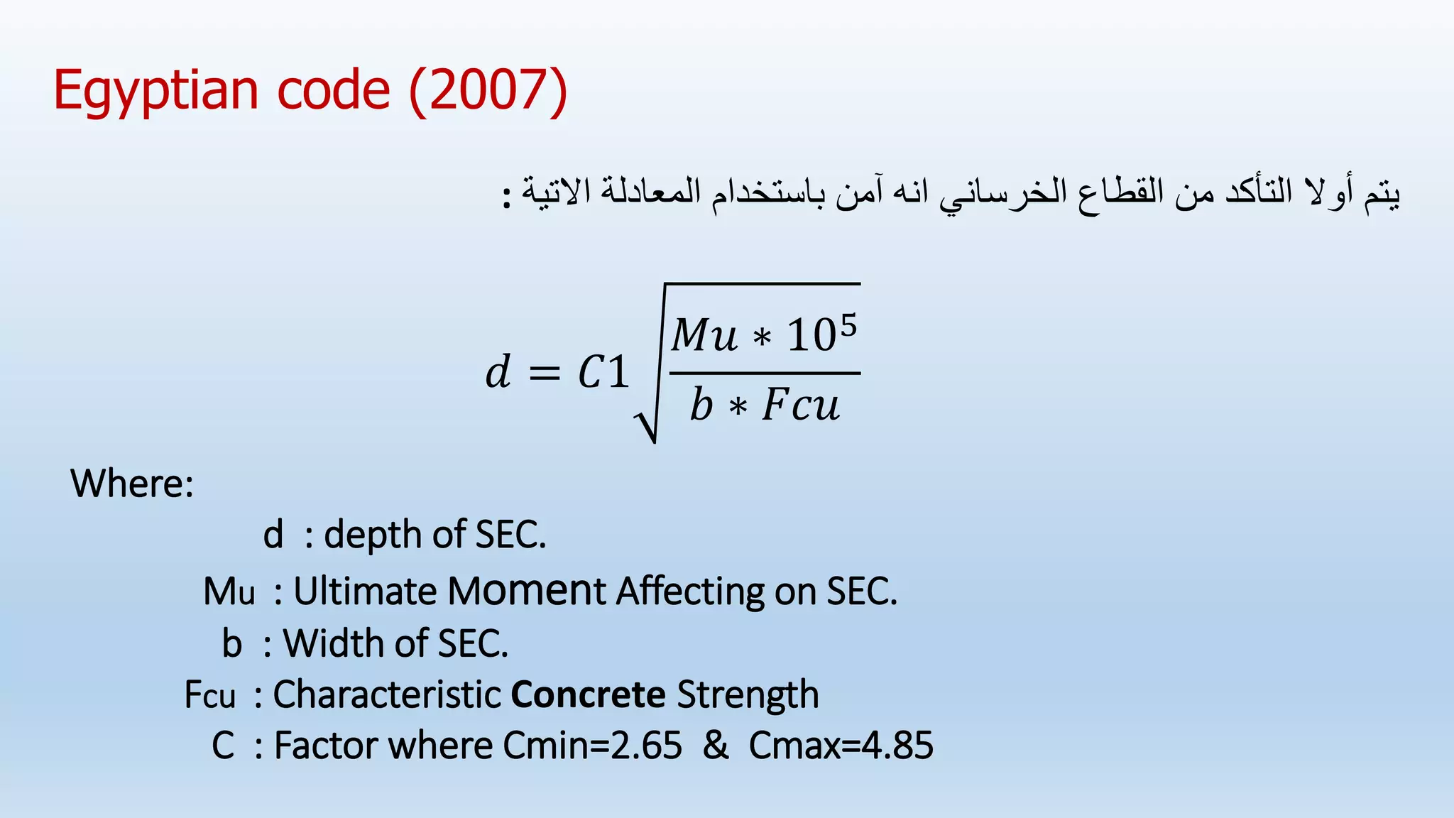
Egyptian code (2007)
𝝲s=1.15[(
7
6
)- (
et
3
)]](https://image.slidesharecdn.com/comparisonbetweencodes-221218164251-fbc0a03b/75/COMPARISON-BETWEEN-CODES-6-2048.jpg)


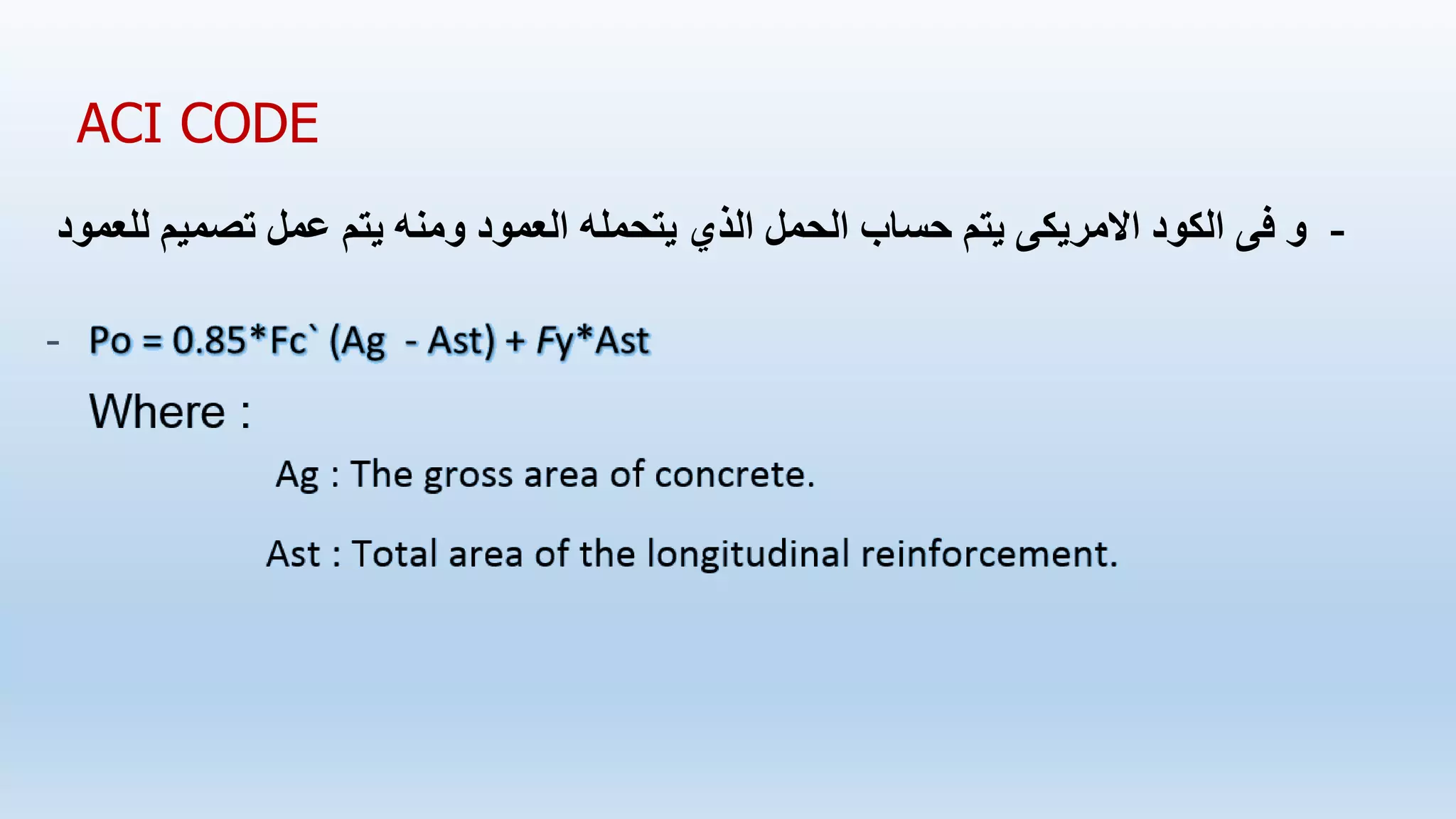
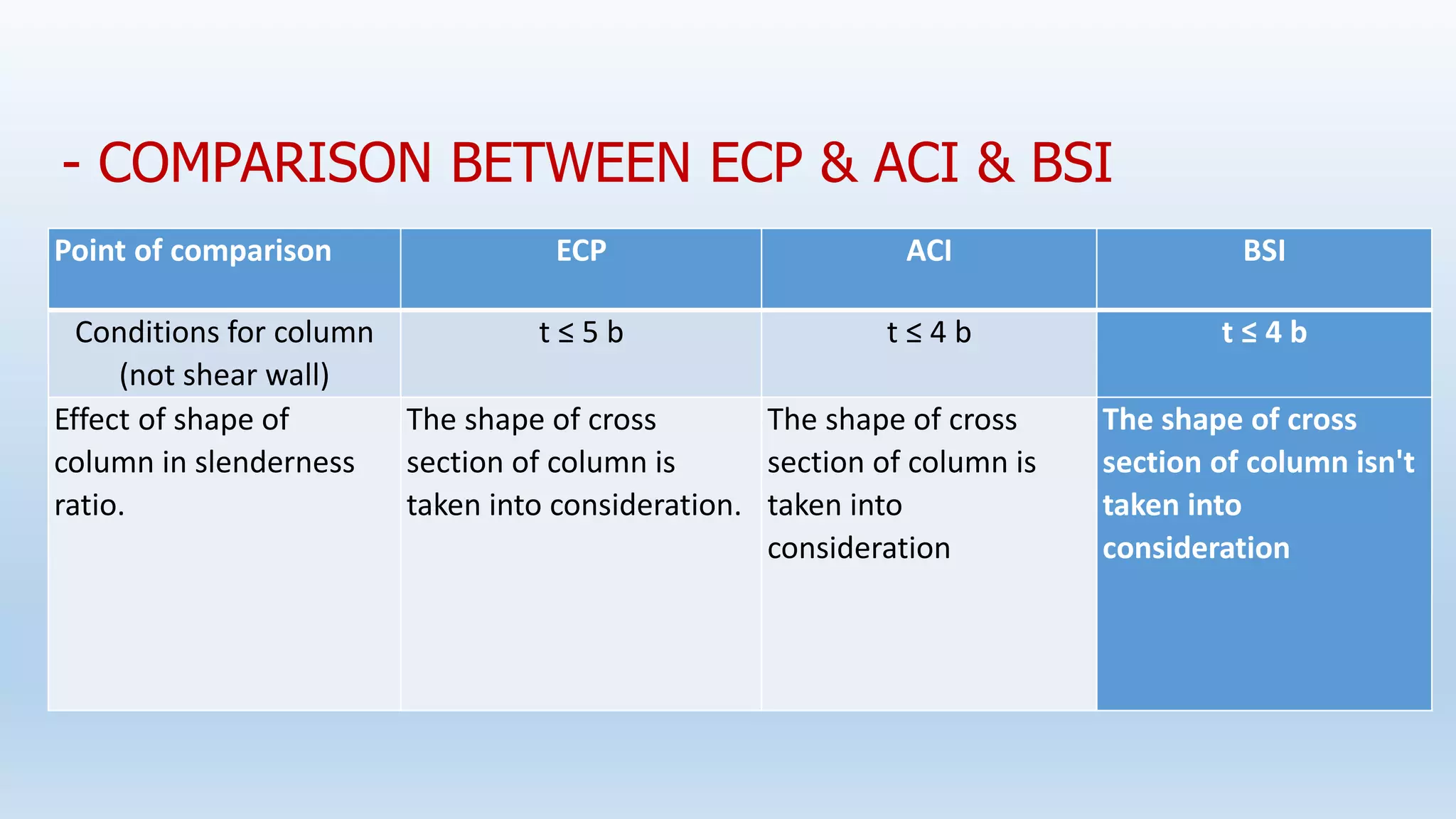


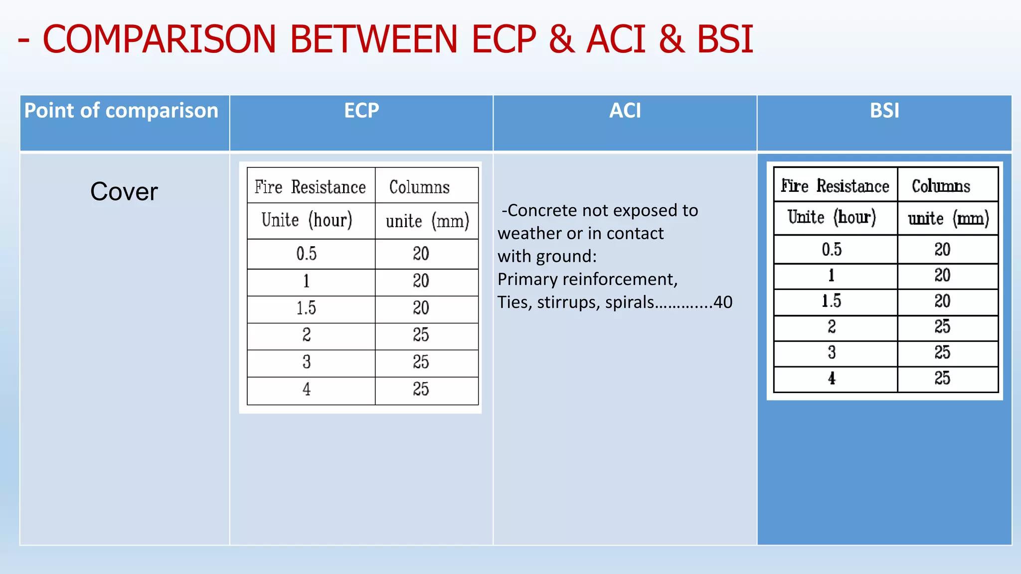
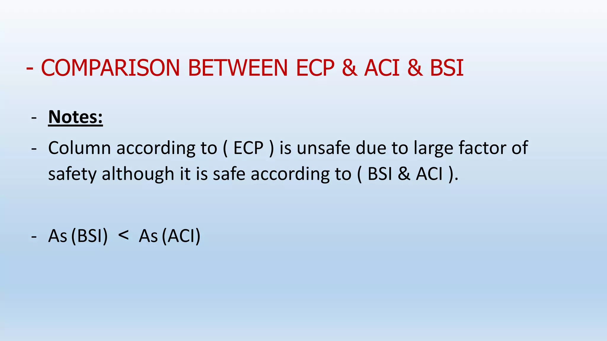


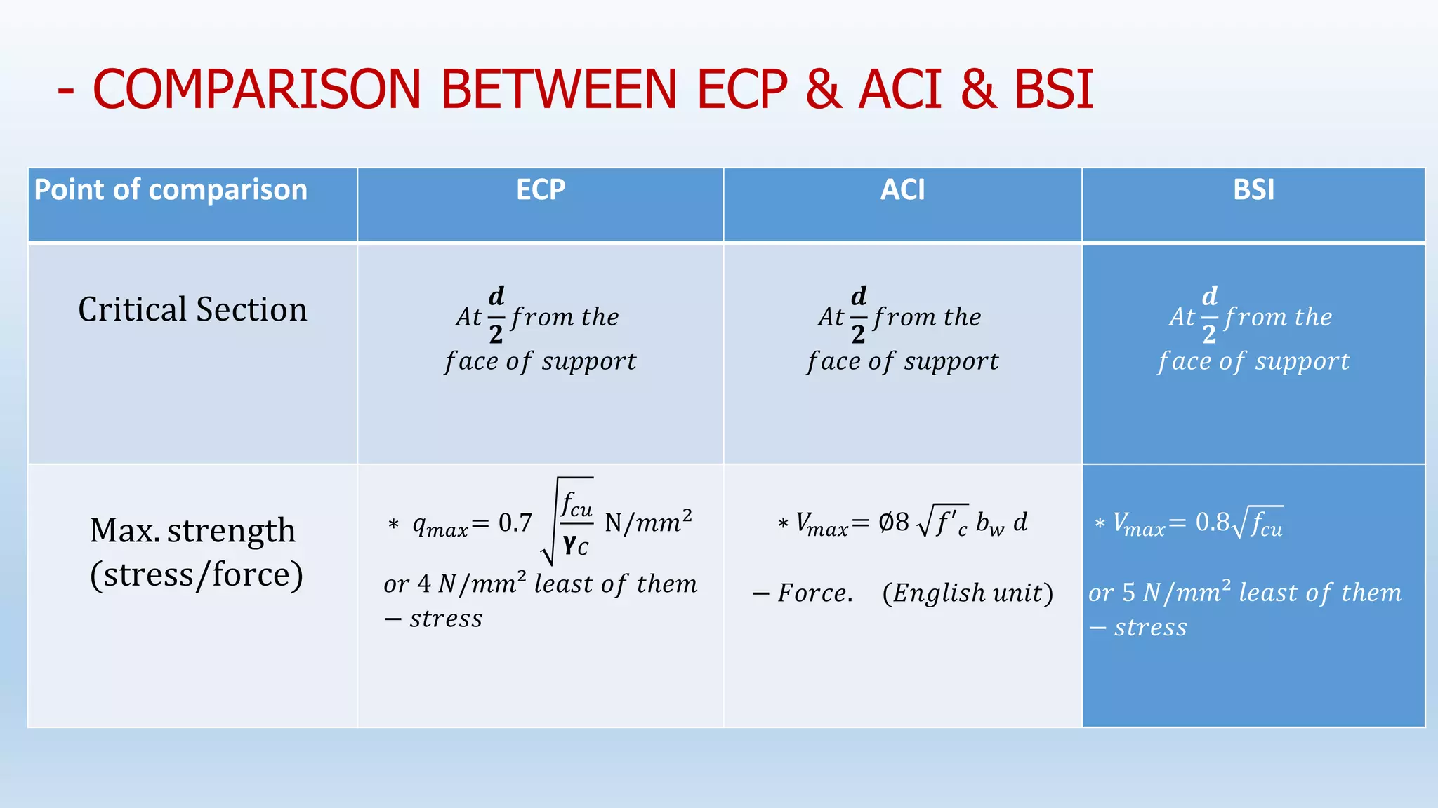


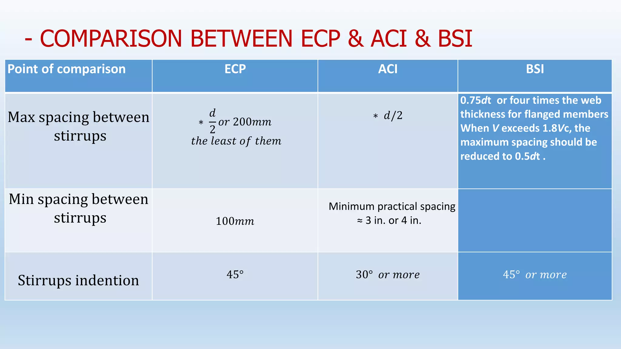
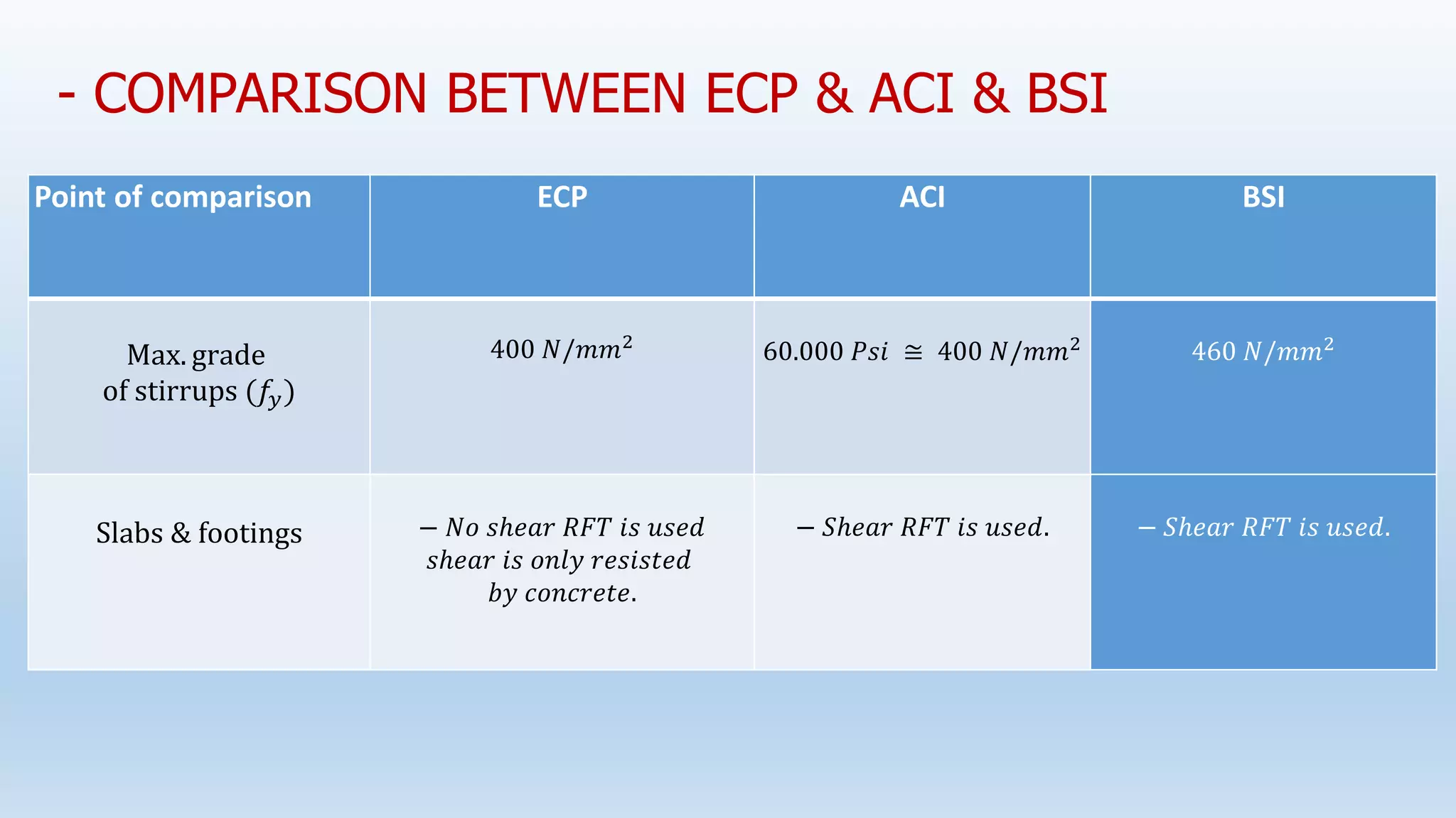


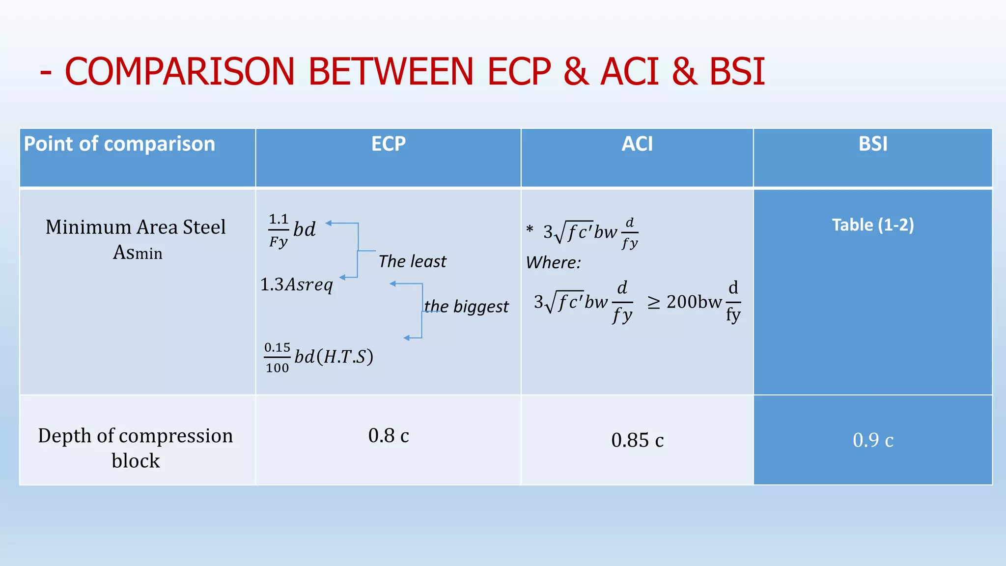
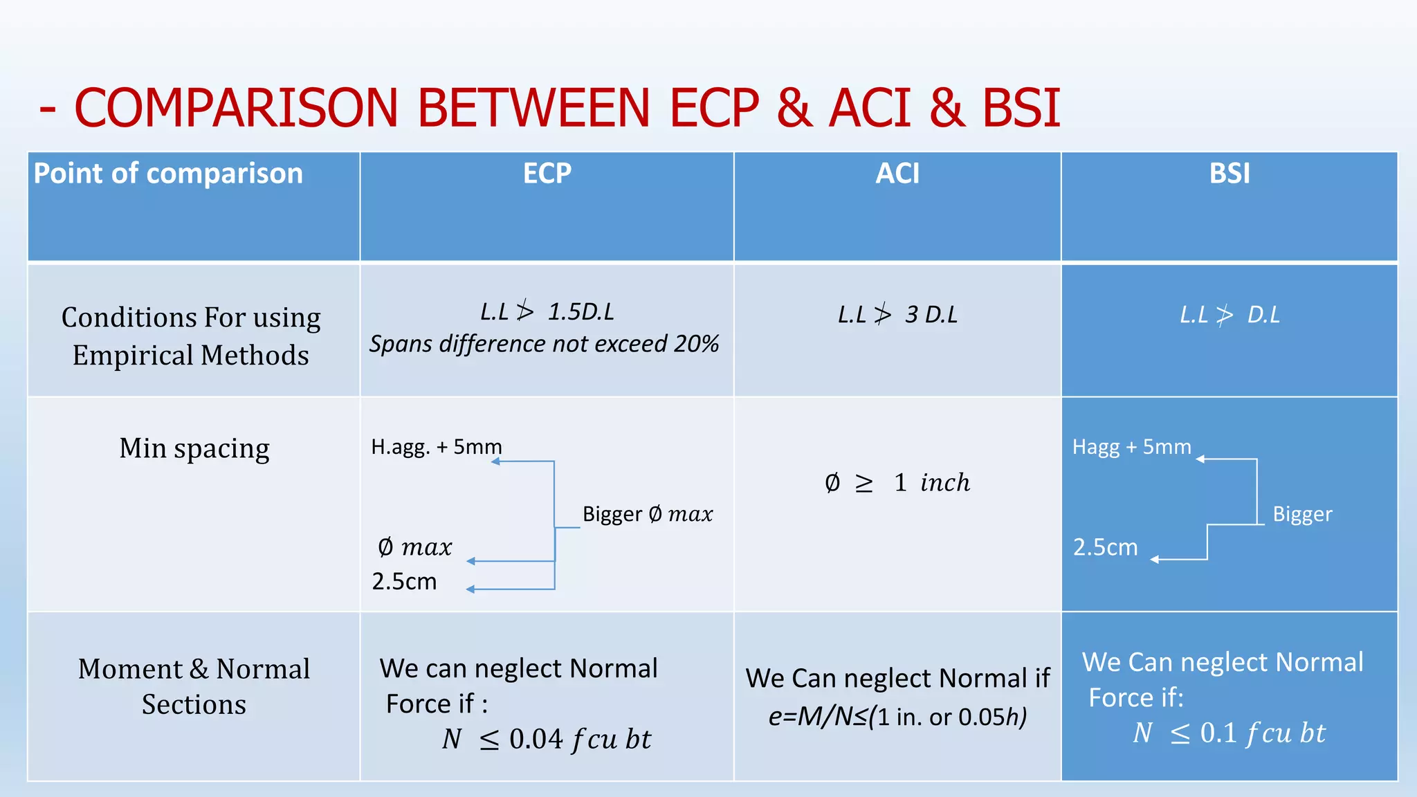


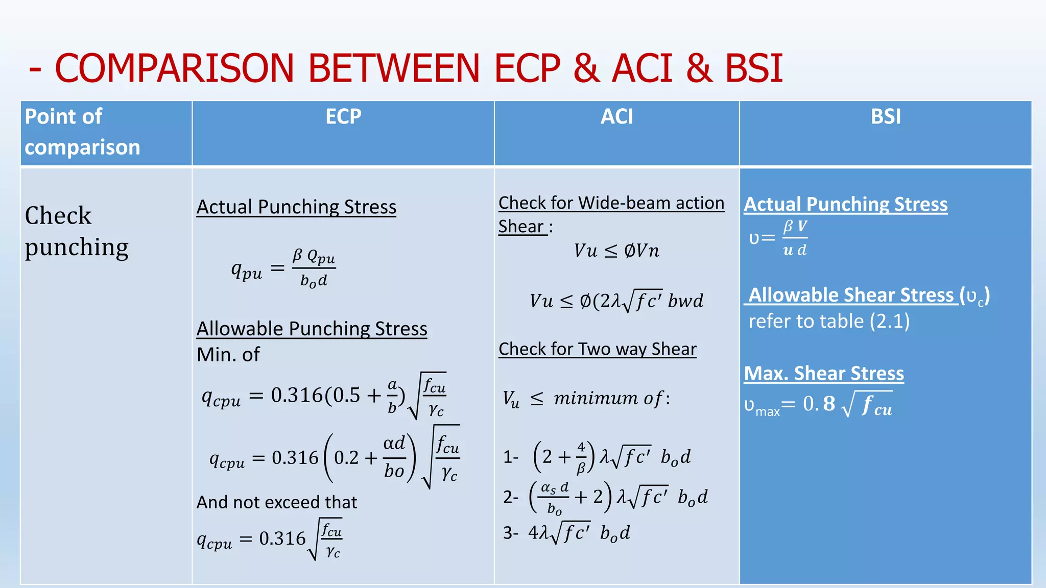


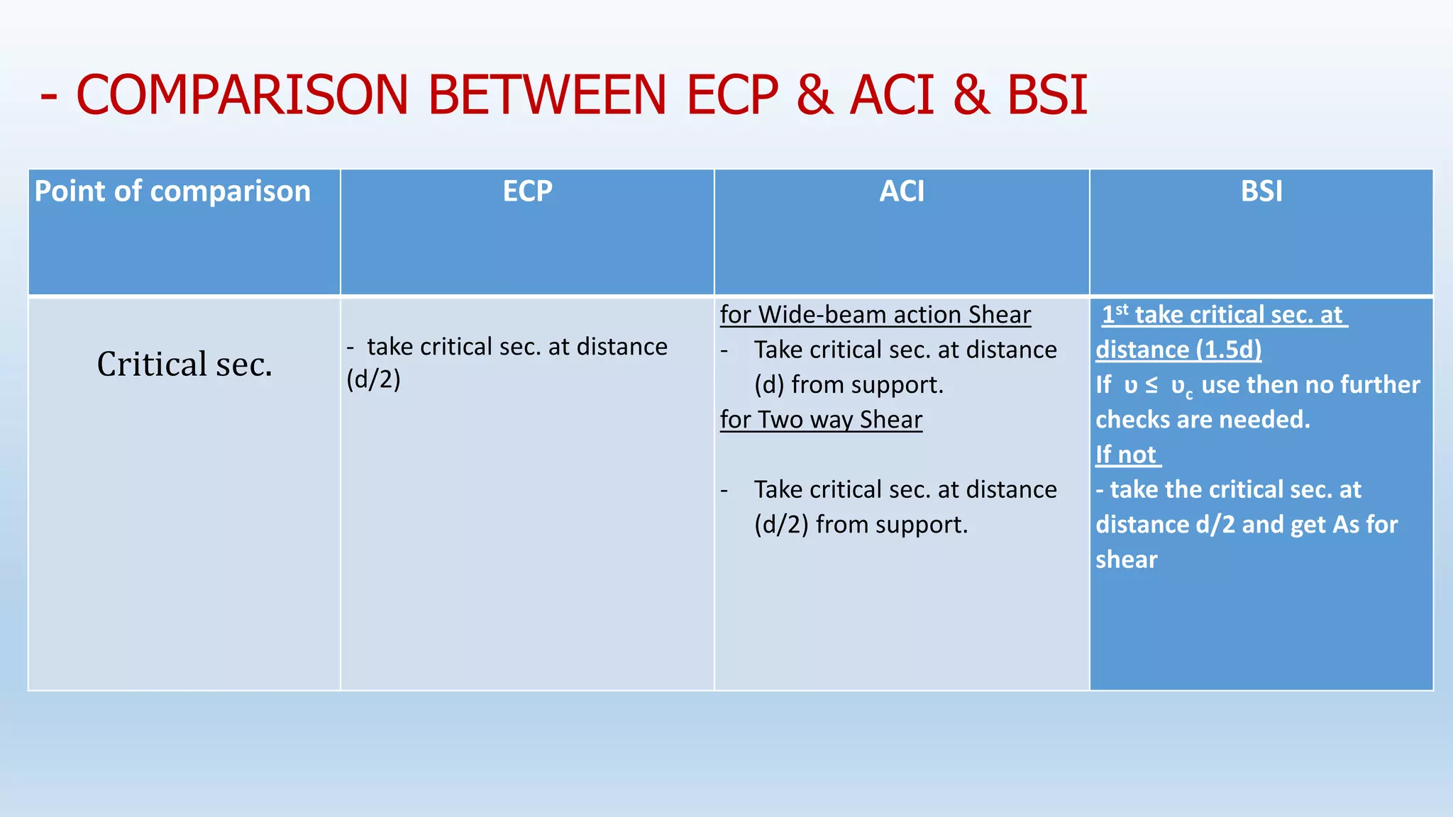


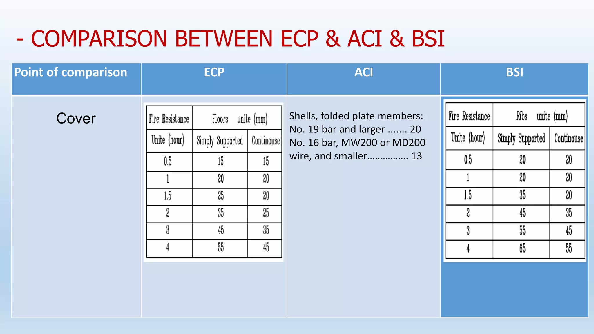

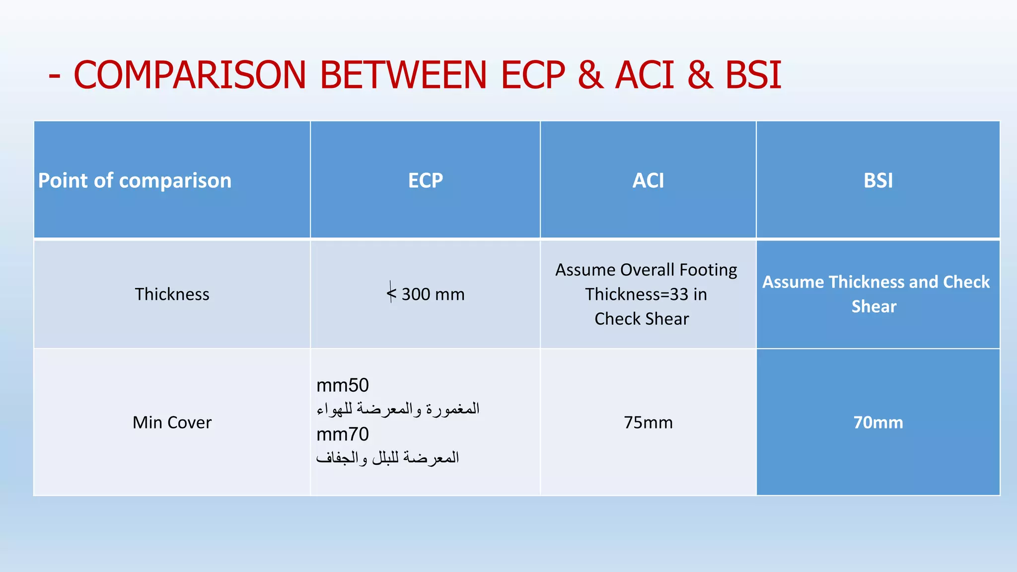
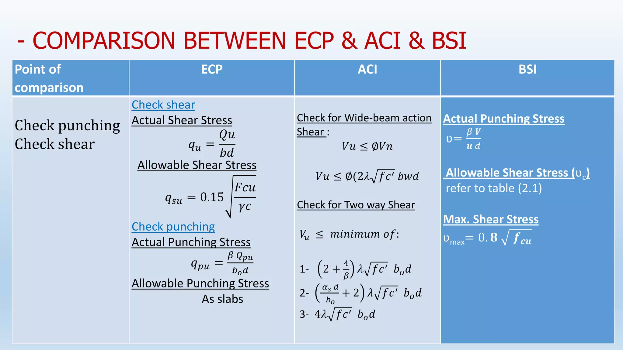

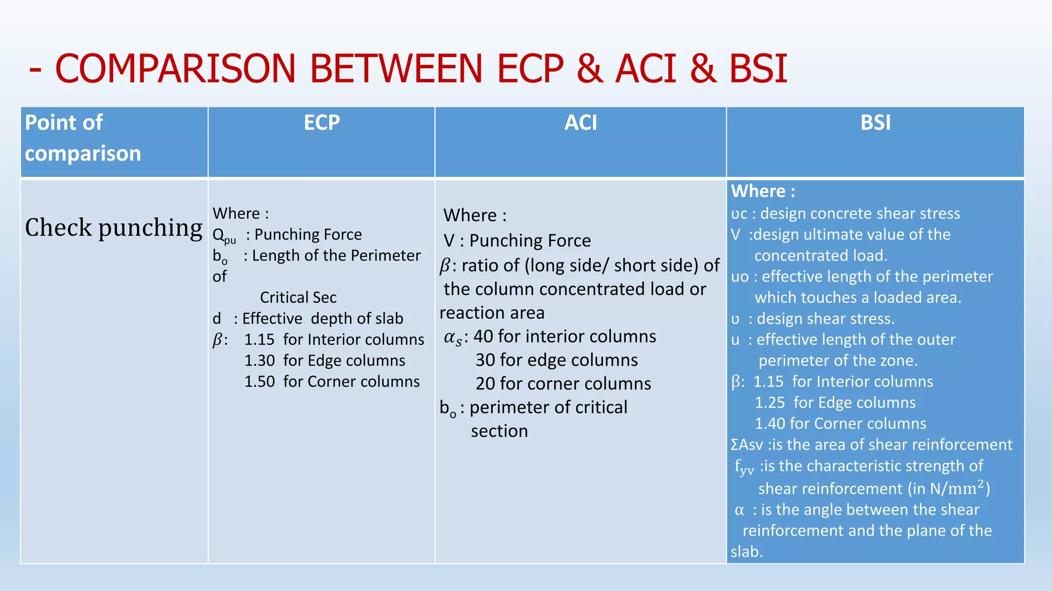
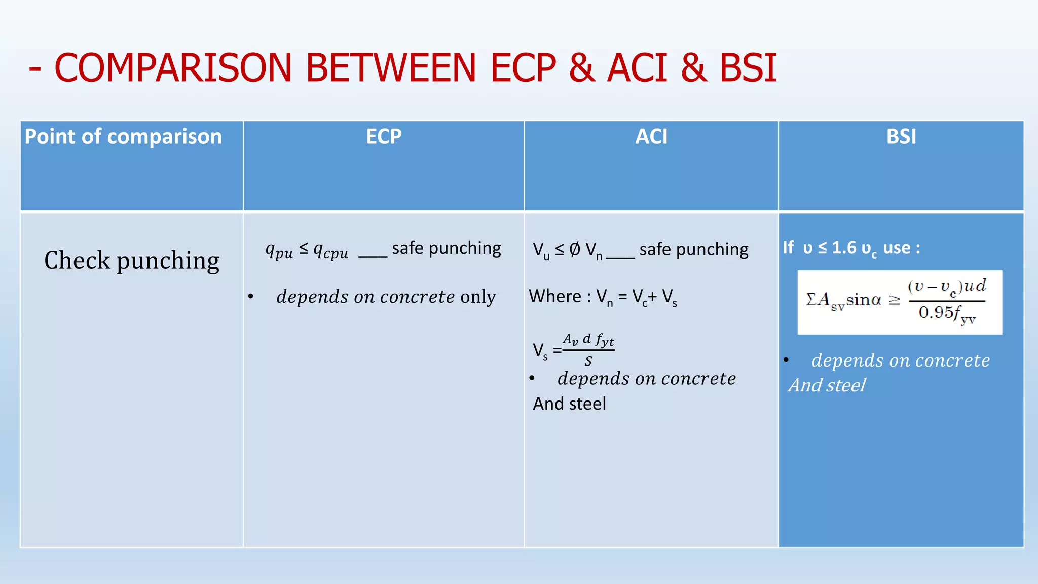


This document compares column and beam design requirements between the Egyptian Code of Practice (ECP), British Standard Institute (BSI), and American Concrete Institute (ACI) codes. For column design, key differences are noted in the calculation of axial load capacity, minimum reinforcement, and effective height considerations. The ECP uses more conservative safety factors. For beams, differences are outlined in critical shear section location and equations for nominal shear strength.