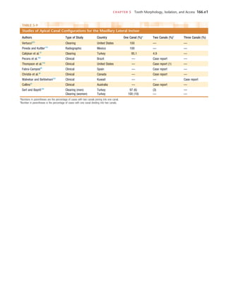
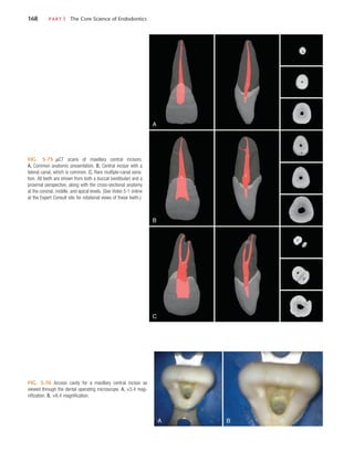
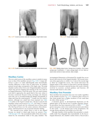
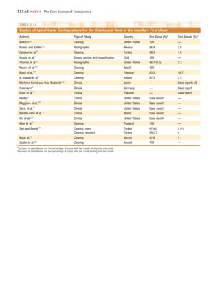
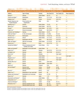
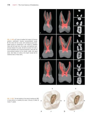
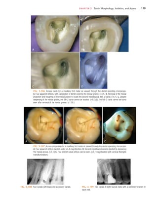
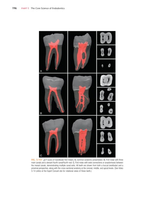
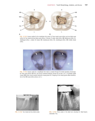
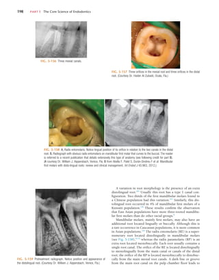
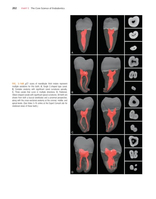
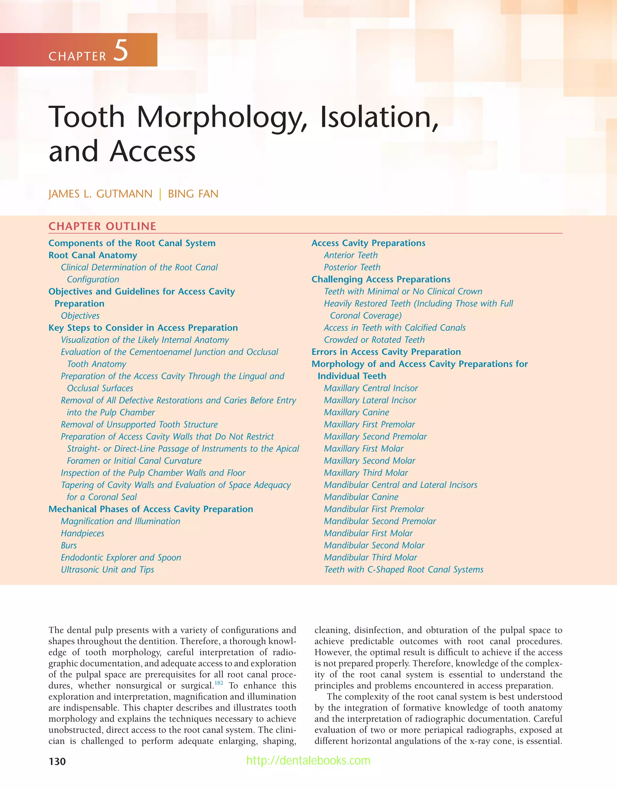
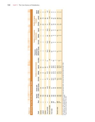
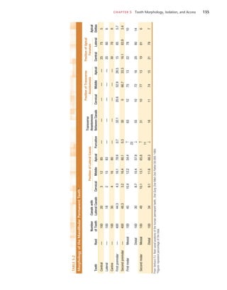
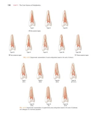
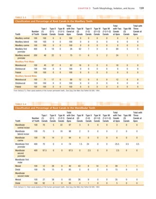
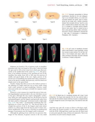
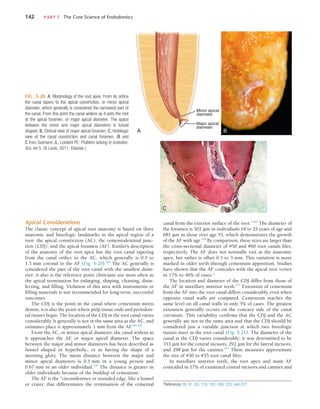
This document discusses root canal anatomy and access cavity preparation for root canal treatment. It describes the components of the root canal system, including the pulp chamber, root canals, accessory canals and apical anatomy. It emphasizes the importance of thorough knowledge of tooth morphology and careful interpretation of radiographs to understand the complex root canal anatomy. The objectives of access cavity preparation are to provide unobstructed access to all root canals to allow for proper cleaning, shaping and filling. Magnification and illumination are important for properly visualizing the pulp chamber floor and locating canal orifices.
![CHAPTER 5 Tooth Morphology, Isolation, and Access 131
These divergently exposed radiographs along with cone-beam
computed tomography (CBCT) scans in some clinical situa-
tions (see Chapter 2) provide important information about
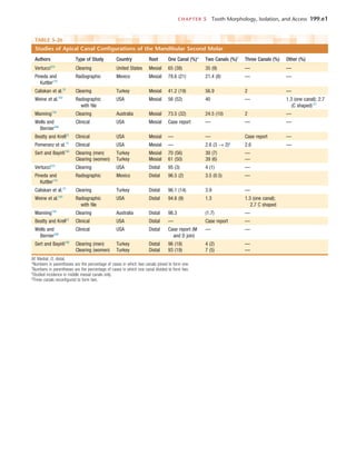
root canal morphology. However, the inclination of the x-ray
tube significantly influences the ability to detect variable root
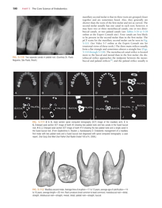
canal systems present in many teeth. For example, in premo-
lars, if the horizontal angle is varied by either 20 or 40 degrees,
the number of root canals seen in the maxillary first and second
premolars and the mandibular first premolars coincides with
the number of canals actually present.134
However, in the man-
dibular second premolar, only the 40-degree horizontal angle
correctly identifies the root canal morphology. The careful
reading and interpretation of each radiograph before and
during root canal procedures is necessary because many teeth
present with unusual canal morphology. Unfortunately, the
interpretation of traditional radiographs may not always result
in the correct morphologic assessment, particularly when only
a buccolingual view is taken. In one study, 790 extracted man-
dibular incisors and premolars were radiographed to assess the
incidence of canal bifurcation in a root.147
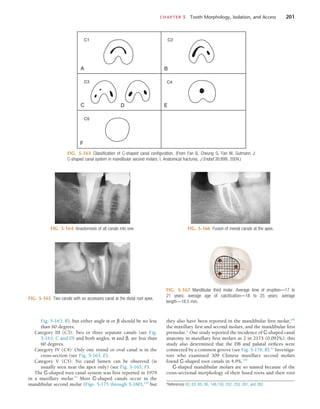
When the fast break
guideline was used (i.e., interpreting a sudden disappearance
or narrowing of a canal as a sign of canal division, such as
bifurcation [Fig. 5-1]), the result was failure to identify one
third of these divisions from a single radiographic view. Thus,
evaluation of the root canal system is most accurate when the
information from several radiographic views is integrated with
a thorough clinical exploration of the interior and exterior
of the tooth. Alternatively, the recent development of micro-
computed tomography (µCT) scanning of teeth has greatly
increased clinical assessment of these complexities and three-
dimensional (3D) relationships found in root canal systems.
The main objectives of root canal procedures are adequate
enlargement, shaping, cleaning, and disinfection of all pulpal
spaces, along with obturation of these spaces with an accept-
able filling material. At times a root canal or its elaborate,
complex system may go undetected, which results in failure
to achieve the stated objectives. Therefore, the use of a vast
array of tools, in particular magnification and illumination,
is essential to accomplish these objectives on a more predict-
able basis.
Initially important aids for determining pulp space mor-
phology, in particular the pulp chamber and location of root
canal orifices, include multiple pretreatment radiographs,
CBCTs, examination of the pulp chamber floor with a sharp
explorer, visual assessment of color changes in the dentin,
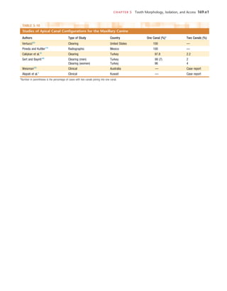
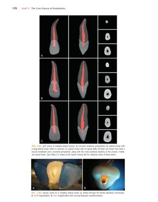
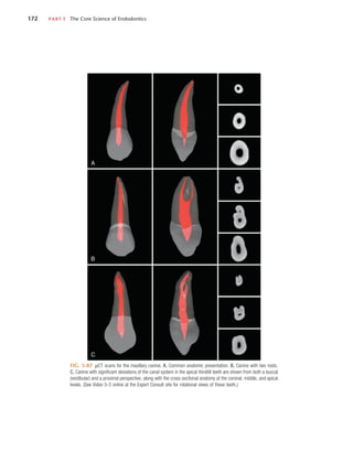
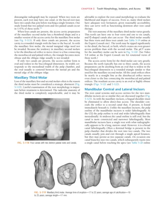
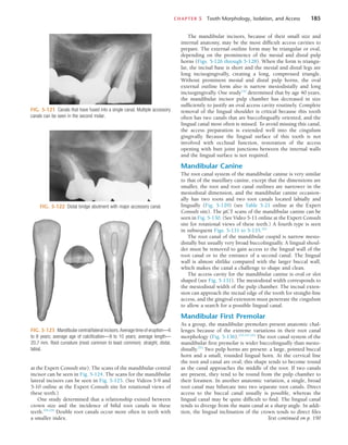
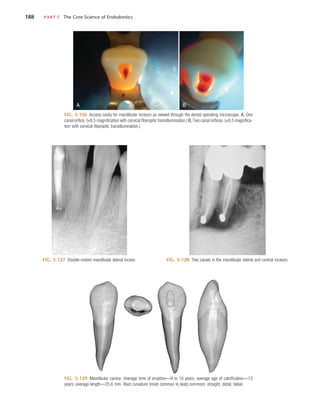
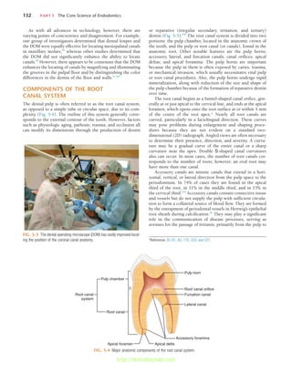
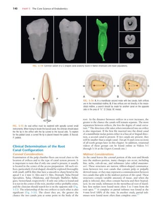
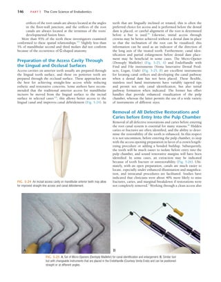
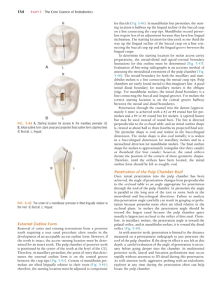
FIG. 5-1 A, Abrupt disappearance of the large canal in the mandibular first premolar indicates a canal bifurca-
tion. B, The same is true for the maxillary first premolar.
A B
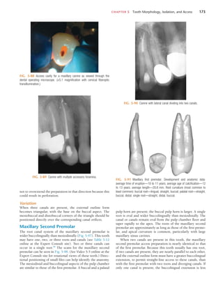
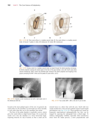
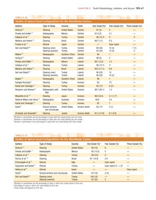
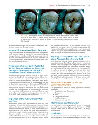
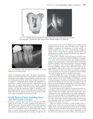
FIG. 5-2 Allowing sodium hypochlorite (NaOCl) to remain in the pulp
chamber may help locate a calcified root canal orifice. Tiny bubbles may
appear in the solution, indicating the position of the orifice. This is best
observed through magnification.
troughing of anatomic grooves with ultrasonic tips, staining
the chamber floor with 1% methylene blue dye, performing a
sodium hypochlorite “champagne bubble” test (Fig. 5-2), visu-
alizing the pulp chamber anatomy from established docu-
ments,107
and root canal bleeding points. Sequential application
of 17% aqueous ethylene diaminetetraacetic acid (EDTA) and
95% ethanol has been recommended for effective cleaning and
drying of the pulp chamber floor before visual inspection.207
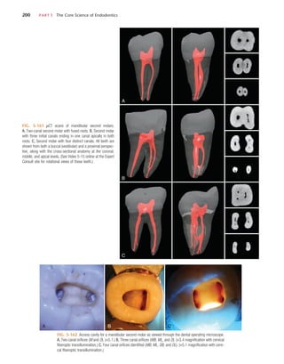
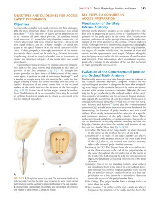
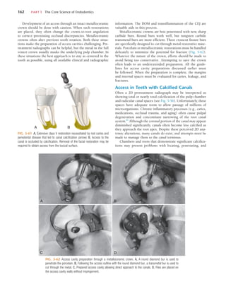
Specifically, the use of the dental operating microscope
(DOM), which is intended to provide superior magnification,
increased lighting, and enhanced visibility,182
is recommended
to determine the location of root canal orifices in the properly
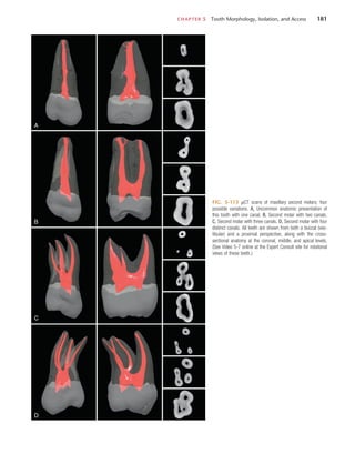
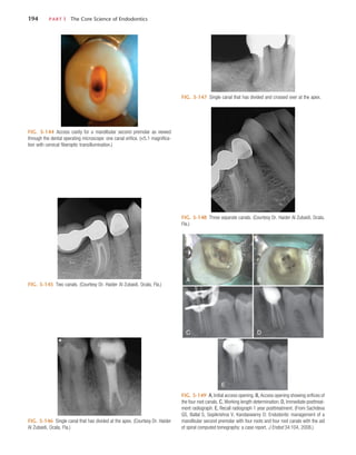
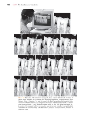
prepared coronal access (Fig. 5-3). Removal of dentin that may
obscure the location of these orifices is also enhanced with
better visualization with the DOM. The DOM also improves the
identification of extra canals (e.g., the mesiopalatal canal found
in many first and second maxillary molars) and has been shown
to be superior to the use of the naked eye and magnifying
loupes for this assessment.14,187
Additional studies have noted
that use of the DOM improves the detection of mesiopalatal
canals to more than 90% in maxillary first molars and 60% in
maxillary second molars.108,207
These evaluative studies demon-
strate that magnification and illumination greatly enhance the
identification of the pulp chamber morphology and ultimately
enable the clinician to achieve better outcomes within each of
the stated objectives for root canal procedures.
http://dentalebooks.com](https://image.slidesharecdn.com/cohens-accessopening-220913122327-51051b1b/85/Cohen-s-Access-Opening-pdf-2-320.jpg)
![CHAPTER 5 Tooth Morphology, Isolation, and Access 163
negotiating the pulpal spaces.84
The use of magnification and
transillumination, as well as careful examination of color
changes and pulp chamber shapes, assists in locating the canals
(Fig. 5-63). However, the search for the root canal orifices
should be made only after the pulp chamber has been com-
pletely prepared and its floor has been cleaned and dried (95%
denatured ethanol may be useful for drying the floor and
enhancing visibility). A fiberoptic light directed through the
CEJ can reveal subtle landmarks and color changes that may
not otherwise be visible. The chamber floor is darker in color
than its walls, and developmental grooves connecting orifices
are lighter in color than the chamber floor. Awareness of these
color differences when searching for calcified orifices is essen-
tial, especially when searching for canal orifices that are located
at the angles formed by the floor and walls and at the end
points of developmental grooves. Additional methods to help
locate calcified root canals include staining the pulp chamber
floor with 1% methylene blue dye, performing the sodium
hypochlorite “champagne bubble” test (see Fig. 5-2) and
searching for canal bleeding points. These approaches are
enhanced when the area is viewed through magnification.
In teeth with significant calcifications that obscure and
block the root canal, the calcified material must be removed
slowly down the root. Long, thin ultrasonic tips should be used
under the high magnification of a DOM to avoid removing too
much tooth structure. As the clinician proceeds apically, expo-
sure of two radiographs should be considered, one from the
straight-on direction and the other from an angled direction.
A very small piece of lead foil placed at the apical extent of the
penetration can provide a radiographic reference.
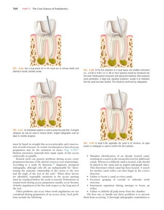
Uncovering canals that contain calcified material is a chal-
lenge. When the canal is located, a small K-file (#6, #8, or #10
or, preferably, a C or C+ file [Dentsply Tulsa and Maillefer,
respectively]) coated with a chelating agent should be intro-
duced into the canal to determine patency. These instruments
provide added stiffness to the shaft for better penetration. The
file should not be removed until some canal enlargement has
occurred. The file should be used in short up-and-down move-
ments and in a selective circumferential filing motion, with
most of the lateral pressure directed away from the furcation.
This enlarges the coronal aspect of the canal safely and moves
it laterally, to avoid thinning of the dentin wall adjacent to the
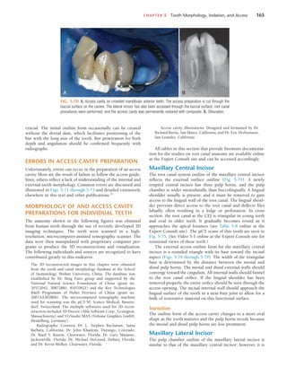
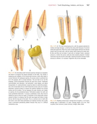
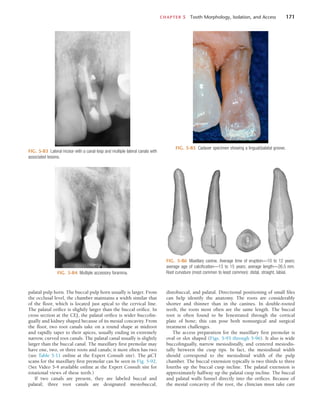
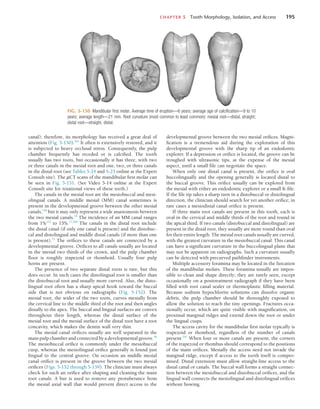
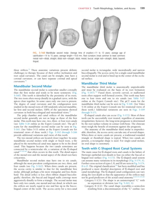
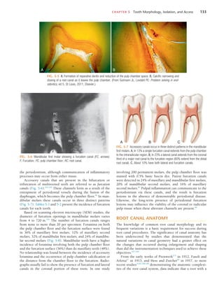
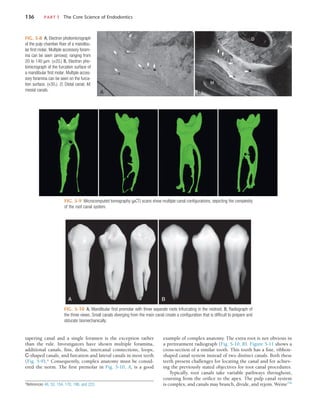
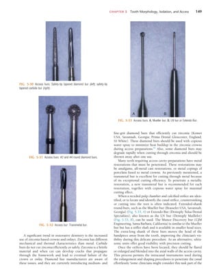
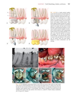
FIG. 5-63 Mandibular molar with what appears to be almost complete
calcification of the pulp chamber and root canals. However, pathosis is
present, which indicates the presence of bacteria and some necrotic tissue
in the apical portion of the roots.
furcation. It also creates a path of insertion for larger files
and for preflaring burs. Figs. 5-64 through 5-69 illustrate
several methods that can be used to locate calcified spaces. For
the most successful results, the sequence should be followed
as shown.
If the canal orifice cannot be found, it is wise to stop exca-
vating the dentin to avoid weakening the tooth structure or
perforating into the periodontal ligament. Management of
these problems can be found in Chapter 19. There is no rapid
technique or solution for dealing with calcified root canals.84
Painstaking removal of small amounts of dentin with the aid
of the DOM and radiographic confirmation has proved to be
the safest approach.
Crowded or Rotated Teeth
Traditional access preparations may not be possible in patients
with crowded teeth. The decision about an alternative approach
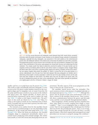
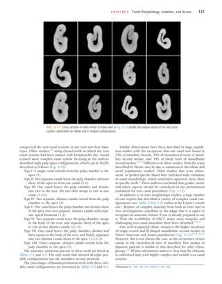
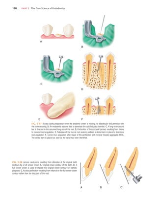
FIG. 5-64 Mandibular first molar with a class I restoration, calcified canals,
and periradicular radiolucencies. Presumably a pulp exposure has occurred,
resulting in calcification and ultimate necrosis of the pulp tissue.
FIG. 5-65 Excavation of a restoration and base material. The cavity prepa-
ration is extended toward the assumed location of the pulp chamber, keeping
in mind that pulp chambers are located in the center of the tooth at the level
of the cementoenamel junction (CEJ).](https://image.slidesharecdn.com/cohens-accessopening-220913122327-51051b1b/85/Cohen-s-Access-Opening-pdf-34-320.jpg)