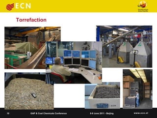
The document summarizes research on co-feeding fibrous biomass and coal into entrained flow gasifiers. It discusses the challenges of biomass as a fuel source and describes how torrefaction can be used as a pre-treatment step to improve biomass properties for gasification. It then outlines the Energy research Centre of the Netherlands' work in developing torrefaction technology, modeling slagging and fouling behavior, and testing biomass and coal mixtures using a lab-scale combustion simulator.

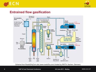

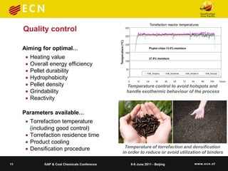
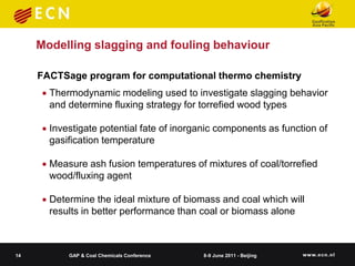
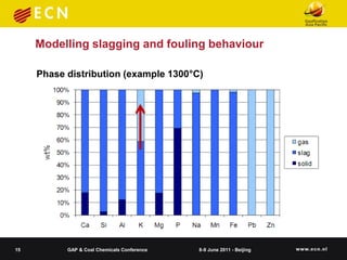
![Modelling slagging and fouling behaviour
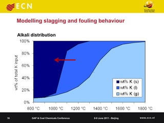
Slagging behavior as function ofelements in biomass for fluxed clean wood fuel
wt% ash mixing slag as f(T) and coal
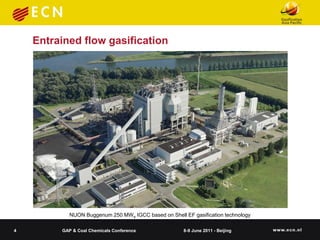
wt% ash elements in slag as f(T) for fluxed clean wood fuel
100
100
90
slag as wt% of fuel ash (incl. flux)
90
slag as wt% of fuel ash (incl. flux)
Original clean wood
80
80
70
70 Silica/fuel ash=0.25 kg/kg
60
60
50
Silica/fuel ash=0.75 kg/kg
50 40
40 30 Silica/fuel ash=1.25 kg/kg
30 20
20 10 Silica/alumina/fuel
10 0 ash=0.5/0.45 kg/kg
0 800 1000 1200 1400 1600 18
800 1000 1200 1400 1600 1800 T [°C]
T [°C]
17 GAP & Coal Chemicals Conference 8-9 June 2011 - Beijing](https://image.slidesharecdn.com/2011beijingcofiringbiomassandcoalineggasifiers-13308590116413-phpapp02-120304050636-phpapp02/85/Cofiring-biomass-amp-coal-17-320.jpg)
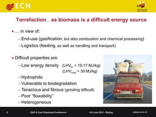
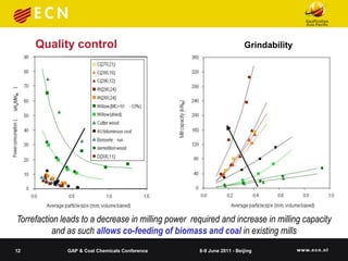
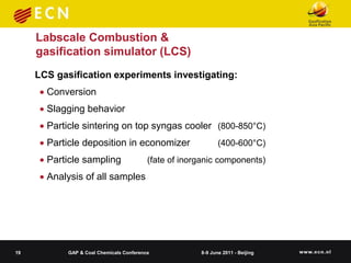
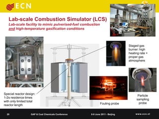
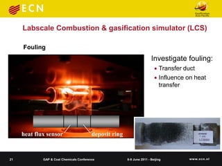
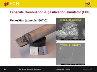
![Labscale Combustion & gasification simulator (LCS)
Residence time/temperature profile (example)
LCS PF facility (controlled conditions, 5 ms up
to 2500ms, 600-1550°C, gas composition)
Temperature [°C]
1000 1200 1400 1600
0 20
90
0,1
0,2 Burner Area
0,3 210
Residence time [ms]
Distance [m] 0,4
0,5
0,6
0,7
1300
0,8
0,9
Furnace Exit
1
18 GAP & Coal Chemicals Conference 8-9 June 2011 - Beijing](https://image.slidesharecdn.com/2011beijingcofiringbiomassandcoalineggasifiers-13308590116413-phpapp02-120304050636-phpapp02/85/Cofiring-biomass-amp-coal-18-320.jpg)
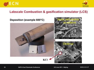
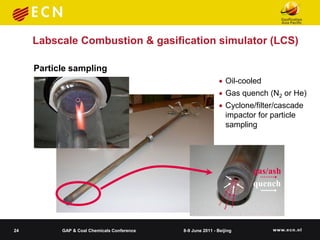
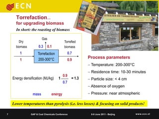
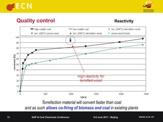
![Labscale Combustion &
gasification simulator (LCS)
Particle sampling
Fractionated samples (lab- & full-scale)
obtained with cascade impactors (CI):
Study release inorganics and
aerosol formation
Provides composition and
morphology of each size 70
fraction 60
plate
stage 1
stage 2
In short: particle sampling
stage 3
weight fraction [% w/w]
50 stage 4
stage 5
allows investigation of 40 stage 6
stage 7
stage 8
all inorganic particles that 30 stage 9
stage 10
enter syngas cooler 20
10
0
25 GAP & Coal Chemicals Conference 8-9 June 2011 - Fe
S Beijing
Na Mg Al Si P Cl K Ca](https://image.slidesharecdn.com/2011beijingcofiringbiomassandcoalineggasifiers-13308590116413-phpapp02-120304050636-phpapp02/85/Cofiring-biomass-amp-coal-25-320.jpg)