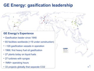
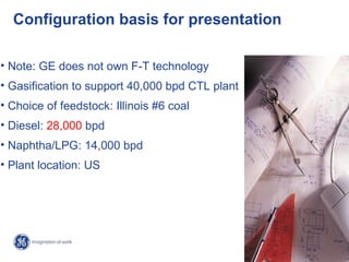
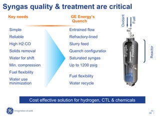
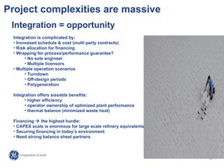
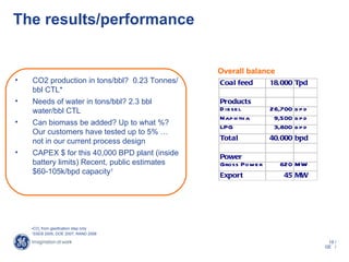
GE Energy
Gasification


World CTL Conference

Robert Carpenter
Marketing Program Manager, Gasification


                                            1/
                                          GE /
Agenda

GE leadership & experience
Important design characteristics
Process description
Critical process elements
Project complexities
+/- of Illinois #6 coal
Key results/data
Summary


                                     2/
                                   GE /
GE leadership & experience
GE Energy: gasification leadership


GE Energy’s Experience
• Gasification leader since 1948
• 65 facilities worldwide (+19 under construction)
• ~120 gasification vessels in operation
• 1966: first heavy fuel oil gasification
• 27 plants today on liquid fuels
• 27 turbines with syngas
• 1MM+ operating hours
                                                       4/
• 33 projects globally that separate CO2             GE /
Continuing to invest in technology
Dr / etInj
  y W ect                                                               HPCoa F
                                                                             l eed       Injection
Ba l e
  ngaor                                                                 Sha i
                                                                           ngha          Technologies
                                                                                         Operability &
                                                                                         Controls
                                                                                         Fuel Flexibility
                                              Dr T F na
                                                op ube ur ce
                                                          Caifor
                                                            l nia
          Conversion                                    Heating Rate

          Controls                                     Residence Time
                                                             (5s)


Quench FowF cil y
        l a it                                         Residence Time
                                                            (40s)
NewY k
    or
                                                                        Proposed R r Cent
                                                                                  eseach er
                                            Conversion                  Wyoming
                              ~   100 Mt/hr
                                            Foulinglb/hr
                                                 ~ 15

                                            Fuel Flexibility

            Entrainment
            Stability & Control                                                          Adv Technologies
            Quench Chamber Design                                                        Operability &
                                                                                         Controls
                                                                                         Fuel Flexibility
                                                                                                          5/
                                                                                                        GE /
The HPG-ATC at the U of Wyoming
              High Plains Gasification Advanced Technology Center:
             Developing the next generation of gasification technologies


• PRB & other coals
• Scaled facility
• Commercial level gasification
  – Dry feed (pressure/metering)
  – Dry injection (spray dispersion)
  – Dry gasification (O/C ratio)
• Complete process blocks                      Status
  –   Coal feeding system                      • Site Selection…May ‘09
  –   Gasification island
  –   Carbon capture systems                   • Start PreFEED…May ‘09
  –   Water treatment systems                  • COD 2012
  –   Data acquisition & controls

                                                                             6/
                                                                           GE /
Important configuration
   characteristics
Configuration basis for presentation

• Note: GE does not own F-T technology
• Gasification to support 40,000 bpd CTL plant
• Choice of feedstock: Illinois #6 coal
• Diesel: 28,000 bpd
• Naphtha/LPG: 14,000 bpd
• Plant location: US


                                                   8/
                                                 GE /
Process description
Indirect CTL with F-T  superior fuels

Coal          Oxygen
                                   Power block


                                                            Fischer-Tropsch
                                                               synthesis
                        Sour     S yngas Cleanup   Sweet
       Gas ification   Syngas        Proces s      Syngas
        Proces s


                         CO2                                                  Clean Fuels
                                                   Sulfur
                        Stream

                  • Proven, commercial process, operating in South Africa
                  • F-T diesel  high cetane, low aromatics, near zero sulfur
                  • Naphtha  straight chain paraffinic, near zero sulfur

                                                                                      10 /
                                                                                     GE /
Process visual model of IGCC plant


                               Click for visual model


                      Today’s discussion focus is here    11 /
                                                         GE /
12 /
GE /
GE’s quench system
configuration
                   GRINDING AND SLURRY      GASIFICATION AND
                                              GAS COOLING                  GAS SCRUBBING
                       PREPARATION

    Oxidant
                                                                                               Particulate Free
 Water                                                                                         Synthesis Gas
                                                                   PARTICULATE
                                                                    SCRUBBER
Coal Feed
                                                       GASIFIER
                    GRINDING
                      MILL
         Recycle                                       Quenched Syngas


                       SLURRY
                        TANK

                                         QUENCH
                       SLURRY            CHAMBER
                        PUMP                           Char                                        Purge Water

                                    LOCKHOPPER                           Clarifier

                                                       Slag
                                         SLAG          Separator
                                         SUMP
                   Coarse Slag to                                                    Recycle
                   Sale/Disposal


                                                                                                               13 /
                                                                                                              GE /
Critical process elements
Syngas quality & treatment are critical
 Key needs                          GE Energy’s


                                                            Oxidant


                                                                          Fuel
                                    Quench

  Simple                           Entrained flow
  Reliable                         Refractory-lined
  High H2:CO                       Slurry feed


                                                                         Product
                                                                Syngas


                                                                                   Reactor
  Solids removal                   Quench configuration
  Water for shift                  Saturated syngas
  Min. compression                 Up to 1200 psig
  Fuel flexibility
                                   Fuel flexibility
  Water use
  minimization                     Water recycle


               Cost effective solution for hydrogen, CTL & chemicals

                                                                                    15 /
                                                                                   GE /
Project complexities
Project complexities are massive
 Integration = opportunity
 Integration is complicated by:
 • Increased schedule & cost (multi party contracts)
 • Risk allocation for financing
 • Wrapping for process/performance guarantee?
       • No sole engineer
       • Multiple licensors
 • Multiple operation scenarios
       • Turndown
       • Off-design periods
       • Polygeneration

 Integration offers sizeable benefits:
      • higher efficiency
      • operator ownership of optimized plant performance
      • thermal balance (minimized waste heat)

 Financing  the highest hurdle:
 • CAPEX scale is enormous for large scale refinery equivalents
 • Securing financing in today’s environment
 • Need strong balance sheet partners


                                                                   17 /
                                                                  GE /
Key results/data
The results/performance


                                                Overall balance
•   CO2 production in tons/bbl? 0.23 Tonnes/    Coal feed      18,000 Tpd
    bbl CTL*
•   Needs of water in tons/bbl? 2.3 bbl         Products
    water/bbl CTL                               D ie se l      26,700 b p d
                                                Nap h th a      9,500 b p d
•   Can biomass be added? Up to what %?         LPG             3,800 b p d
    Our customers have tested up to 5% …
    not in our current process design           Total          40,000 bpd

•   CAPEX $ for this 40,000 BPD plant (inside   Power
    battery limits) Recent, public estimates    Gross Powe r      620 MW
    $60-105k/bpd capacity1                      Export             45 MW


    •CO2 from gasification step only
    1
      SSEB 2005, DOE 2007, RAND 2008

                                                                               19 /
                                                                              GE /
Summary
Summary

GE leadership & experience
Important design characteristics
Process description
Critical process elements
Project complexities
+/- of Illinois #6 coal
Key results/data
Summary
       www.ge-energy.com/gasification
         robert1.carpenter@ge.com


                                         21 /
                                        GE /
GE Energy
Gasification


World CTL Conference
                        22 /
                       GE /

Robert Carpenter

World Coal-to-Liquids Presentation

  • 1.
    GE Energy Gasification World CTLConference Robert Carpenter Marketing Program Manager, Gasification 1/ GE /
  • 2.
    Agenda GE leadership &experience Important design characteristics Process description Critical process elements Project complexities +/- of Illinois #6 coal Key results/data Summary 2/ GE /
  • 3.
    GE leadership &experience
  • 4.
    GE Energy: gasificationleadership GE Energy’s Experience • Gasification leader since 1948 • 65 facilities worldwide (+19 under construction) • ~120 gasification vessels in operation • 1966: first heavy fuel oil gasification • 27 plants today on liquid fuels • 27 turbines with syngas • 1MM+ operating hours 4/ • 33 projects globally that separate CO2 GE /
  • 5.
    Continuing to investin technology Dr / etInj y W ect HPCoa F l eed Injection Ba l e ngaor Sha i ngha Technologies Operability & Controls Fuel Flexibility Dr T F na op ube ur ce Caifor l nia Conversion Heating Rate Controls Residence Time (5s) Quench FowF cil y l a it Residence Time (40s) NewY k or Proposed R r Cent eseach er Conversion Wyoming ~ 100 Mt/hr Foulinglb/hr ~ 15 Fuel Flexibility Entrainment Stability & Control Adv Technologies Quench Chamber Design Operability & Controls Fuel Flexibility 5/ GE /
  • 6.
    The HPG-ATC atthe U of Wyoming High Plains Gasification Advanced Technology Center: Developing the next generation of gasification technologies • PRB & other coals • Scaled facility • Commercial level gasification – Dry feed (pressure/metering) – Dry injection (spray dispersion) – Dry gasification (O/C ratio) • Complete process blocks Status – Coal feeding system • Site Selection…May ‘09 – Gasification island – Carbon capture systems • Start PreFEED…May ‘09 – Water treatment systems • COD 2012 – Data acquisition & controls 6/ GE /
  • 7.
    Important configuration characteristics
  • 8.
    Configuration basis forpresentation • Note: GE does not own F-T technology • Gasification to support 40,000 bpd CTL plant • Choice of feedstock: Illinois #6 coal • Diesel: 28,000 bpd • Naphtha/LPG: 14,000 bpd • Plant location: US 8/ GE /
  • 9.
  • 10.
    Indirect CTL withF-T  superior fuels Coal Oxygen Power block Fischer-Tropsch synthesis Sour S yngas Cleanup Sweet Gas ification Syngas Proces s Syngas Proces s CO2 Clean Fuels Sulfur Stream • Proven, commercial process, operating in South Africa • F-T diesel  high cetane, low aromatics, near zero sulfur • Naphtha  straight chain paraffinic, near zero sulfur 10 / GE /
  • 11.
    Process visual modelof IGCC plant Click for visual model Today’s discussion focus is here 11 / GE /
  • 12.
  • 13.
    GE’s quench system configuration GRINDING AND SLURRY GASIFICATION AND GAS COOLING GAS SCRUBBING PREPARATION Oxidant Particulate Free Water Synthesis Gas PARTICULATE SCRUBBER Coal Feed GASIFIER GRINDING MILL Recycle Quenched Syngas SLURRY TANK QUENCH SLURRY CHAMBER PUMP Char Purge Water LOCKHOPPER Clarifier Slag SLAG Separator SUMP Coarse Slag to Recycle Sale/Disposal 13 / GE /
  • 14.
  • 15.
    Syngas quality &treatment are critical Key needs GE Energy’s Oxidant Fuel Quench Simple Entrained flow Reliable Refractory-lined High H2:CO Slurry feed Product Syngas Reactor Solids removal Quench configuration Water for shift Saturated syngas Min. compression Up to 1200 psig Fuel flexibility Fuel flexibility Water use minimization Water recycle Cost effective solution for hydrogen, CTL & chemicals 15 / GE /
  • 16.
  • 17.
    Project complexities aremassive Integration = opportunity Integration is complicated by: • Increased schedule & cost (multi party contracts) • Risk allocation for financing • Wrapping for process/performance guarantee? • No sole engineer • Multiple licensors • Multiple operation scenarios • Turndown • Off-design periods • Polygeneration Integration offers sizeable benefits: • higher efficiency • operator ownership of optimized plant performance • thermal balance (minimized waste heat) Financing  the highest hurdle: • CAPEX scale is enormous for large scale refinery equivalents • Securing financing in today’s environment • Need strong balance sheet partners 17 / GE /
  • 18.
  • 19.
    The results/performance Overall balance • CO2 production in tons/bbl? 0.23 Tonnes/ Coal feed 18,000 Tpd bbl CTL* • Needs of water in tons/bbl? 2.3 bbl Products water/bbl CTL D ie se l 26,700 b p d Nap h th a 9,500 b p d • Can biomass be added? Up to what %? LPG 3,800 b p d Our customers have tested up to 5% … not in our current process design Total 40,000 bpd • CAPEX $ for this 40,000 BPD plant (inside Power battery limits) Recent, public estimates Gross Powe r 620 MW $60-105k/bpd capacity1 Export 45 MW •CO2 from gasification step only 1 SSEB 2005, DOE 2007, RAND 2008 19 / GE /
  • 20.
  • 21.
    Summary GE leadership &experience Important design characteristics Process description Critical process elements Project complexities +/- of Illinois #6 coal Key results/data Summary www.ge-energy.com/gasification robert1.carpenter@ge.com 21 / GE /
  • 22.
    GE Energy Gasification World CTLConference 22 / GE / Robert Carpenter

Editor's Notes

  • #5 Why not leverage the existing infrastructure that we have today? Oil refineries make a variety of liquid fuels, many of which are highly valued in the global market. But, we are typically left with heaver fuels, with little external market value. Why not leverage these for power? Instead of tying to mix these heavier liquids to make a fuel suitable for power generation, why not use the heavier ends directly. Describe schematic: 1. To deal with these heavier liquid fuels, we offer a new concept …. Split or separate the heavy liquid ends from the refinery. Once split, the lighter liquids could be sent to a gas turbine … these liquids are well within current gas turbine capabilities, especially as most of the contaminants will end up in the heavier fraction. (Need emphasis here) The heavier fuel fraction can then be gasified. This is a chemical process in which the fuel is partially oxidixed and produces a hydrogen based fuel (syngas), which can be cleaned and burned in a gas turbine. This is a well known process …. GE has more than 1 million gas turbine operating hours on these types of fuels; Once example is a plant in Italy which is gasifying petrolelum (pet) coke to produce syngas which is used to fuel a set of gas turbines, producing 500 MW (net power). This slide strengthens the idea of direct firing of GT’s , as a higher performing platform than a traditional steam boiler. And the right side promotes the years of gasification experience, numbers of value streams; syngas, metals, sulfur, CO2.
  • #12 CTL block diagram
  • #14 Slurry/liquid feed simple, safe, versatile, efficient, Reactor design downflow, simple, good solids removal, Wide range of possible operating variables pressure, feeds, optimize overall system, Gas Cooling by either water quench or high pressure steam generation. After the gasification reaction, the gas is cooled and scrubbed free of particulates in a water scrubbing system. This generates a hot clean syngas, saturated with water, and still containing H2S. Ash settles in the water bath and is removed from the high pressure reaction area via a lockhopper. Soot or char high in carbon is concentrated in a settler and recycled to the gasifier. Low carbon ash is sold or disposed of offsite. For solid feeds, the feedstock is ground with water to form a slurry. The slurry is then pumped to the gasifier. For oil feeds, the grinding mill is eliminated and the oil is pumped to the gasifier. Because of the similarity in feed systems for both solids and oil, we have great feedstock flexibility and some commercial units have changed feedstocks as the cost of feedstock has changed.
  • #18 Turndown issues – refineries have daytanks. These don’t can’t.