Downloaded 17 times


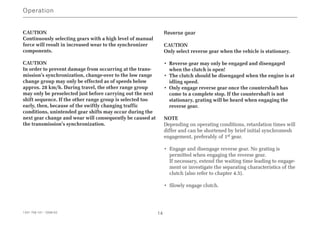
![3.7 Towing
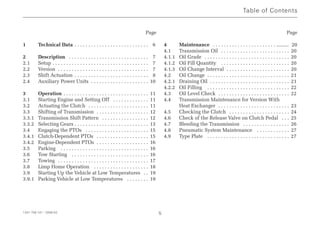
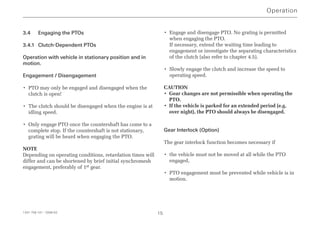
Vehicles may only be towed under the following
conditions:
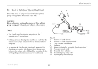
• Emergency steering pump fitted
• High range selected, shift lever in neutral position
• Towing distance of max. 100 km
• The max. permissible towing speed should be defined
depending on axle ratio and tire size using the diagram
provided (also refer to Fig. 8).
NOTE
Vehicle manufacturer specifications MUST be observed.
CAUTION
If one of the aforementioned conditions is not satisfied,
the propshaft must always be deflanged from the rear
axle or the stub shafts must be removed in order to
prevent transmission damage from occurring.
If you suspect transmission damage, the propshaft must
also be deflanged from the rear axle or the stub shafts
must be removed.
Fig. 8
Example (reading): iAxle = 6, Rdyn = 0.5 m
Towing speed from diagram:
Vmax = 25 km/h
NOTE
Relevant local legislation relating to max. towing speeds
must be observed.
Operation
1341 758 101 - 2006-02 17
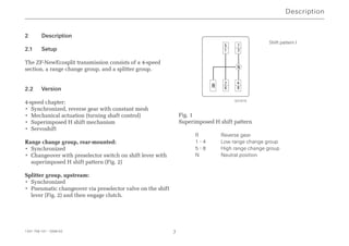
2.0
3.0
4.0
5.0
6.0
7.0
8.0
10 15 20 25 30 35 40 45 50
[i Axle]
V [km/h]
Rdyn 0.5 [m] (z.B. 275/80R22.5)
Rdyn 0.6 [m] (z.B. F24)
Rdyn 0.4 [m] (z.B. 245/70R19.5)
027279_en](https://image.slidesharecdn.com/zfecosplit1341758101operatinginstructions-220827153154-2cdd1e15/85/ZF-Ecosplit-1341_758_101-Operating-Instructions-pdf-17-320.jpg)
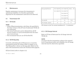

This document provides operating instructions for a ZF synchromesh transmission. It begins with an overview of the transmission components and shift actuation methods. It then provides guidance on starting the vehicle, engaging the clutch, shifting gears, engaging power take-offs, parking, towing, and maintenance. Proper operation and maintenance are emphasized to ensure reliability and cost-effective driving.


