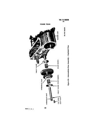
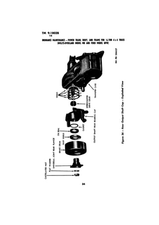
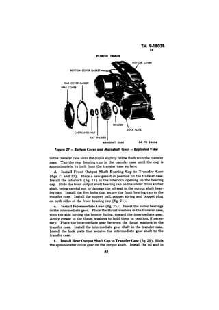
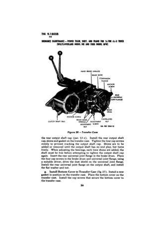
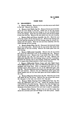
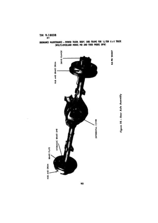
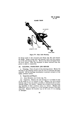
SCOPE. 
a. 
g. 
:
RA PD 28742
TM 9;1803B 
2. MWO AND MAJOR UNIT ASSEMBLY REPLACEMENT 
RECORD. 
a. Description. 
b. _Instructions for Use. 
Early Modifications.
CHAPTER 2 
Section I 
3. POWER TRAIN DESCRIPTION. 
a. The power from the engine is transmitted to the driving wheels 
through a transmission and a transfer case, each of which provides 
a means of selecting the gear reduction. The power from the trans-fer 
case is transmitted to the front and rear axles through propeller 
shafts equipped with universal joints. The transmission is located 
at the rear of the engine and is secured to the clutch housing (fig. 2 ). 
The various gears in the transmission (par. 4) are controlled by a 
shift lever. The transfer case is mounted directly onto the rear of 
the transmission. The transmission output shaft extends from the 
rear of the transmission into splines of the main drive gear in the 
transfer case. The transfer case is provided with two levers, one to 
select the transfer case ratio, and the other to engage or disengage 
the front axle (fig. 5). A hand brake drum is mounted on the rear 
axle output shaft Each axle is of the spiral bevel hypoid gear full-floating 
type, equipped with the conventional differential. 
Section II 
4. DESCRIPTION AND DATA. 
a. Deecription. The transmission (fig. 3) is of the %-speed type 
with synchronized second and high speed gears. The transmission 
and transfer case are mounted on rubber on the frame center cross-’ 
member. The gearshift lever is incorporated in the gearshift housing. 
b. Data. 
Make . . . . . . . . . . . . . . . . . . . . . . . . . . . . . . . . . . . . . . . . . . . . . . . . . . . . . . . . . . . . . . . . . . . , . Warner 
Model . . . . . . . . . . . . . . . . . . . . . . . . . . . . . . . . . . . . . . . . . . . . . . . . . . . . . . . . . . . . . . . . . . . . . . . . . . . . . . . . . . . . . . . . . . . . T84J 
Type . . . . . . . . . . . . . . . . . , . . , . . . . . . . . . . . . . . . . . . . . . . . . . . . . . . . . . . . . . . . . . . Synchronous Mesh 
speeds: 
Forward . . . . . . . . . . . . . , . . . . . . . . . . . . . . . . . . . . . . . . . . . . . . . . . . . . . . . . . . . . . . . . . . . . . . . . . . . . . . , . . . . . . . . . 3 
Reverse . . . . . . . . . . . . . . . . . . . . . . . . . . . . . . . . . . . . . . . . . . . . . . . . . . . . . . . . . . . . . . . . . . . . . . . . . . . 1 
Ratios: 
Low . . . . . . . . . . . . . . . . . . . . . . . . . . . . . . . . . . . . . . . . . . . . . . . . . . . . . . . . . . . . . . . . . . . . . . . . . . . . . . . . . . . . 2.665 to 1 
Second . . . . . . . . . . . . . . . . . . . . . . . . . . . . . . . . . . . . . . . . . . . . . . . . . . . . . . . . . . . . . . . . . . . . . . . . . 1.564 to 1 
7
4 
IAW 
a L
POWER TRAIN 
TM 9-18038 
1 
Figure 3 - Transmission - Three-quarter Front View 
Figure 4 - Transmission - Three-quarter Rear View 
9
FRAMFEO R( /,-TON 
, 
Transmission and Shift Levers 
High . . . . . . . . . . . . . . . . 1to1 
Reverse . . . . . . . . . . . . . . . . . .._._........................................................ 3.554 to 1 
Bearings: 
Clutch shaft (flywheel) .._, ._.. _.. . ..__. . . . . . . . . . . . . . . . Bushing 
Clutch release . . . . . . . . . . . . Ball 
Clutch shaft rear (main drive gear) . . . . . . . . . . . . . . Ball 
Mainshaft front . . _. . . . . . _. _. . . . . . . . . . 13 rollers 
Mainshaft rear . . . . . . . . . .._..._.......................................................... Ball 
Countershaft gear . .. . . . . . . . . . . Bushings (2 ) 
Reverse idle gear . _.. . . . . , . . . . . . . . . . Bushing 
5. 
Remove the 
cap screws from the floor plate at the transmission, and remove the 
floor plate. Remove the gearshift housing cap and remove the shift 
lever from the transmission. Remove the set screw that secures the 
shift lever pivot pin on the transfer case and, with a suitable drift, 
remove the shift lever pivot pin. Remove the two shift levers and 
shift lever springs from the transfer case. Remove the two cap screws 
that secure the clutch housing inspection plate and remove the in-spection 
plate. 
10
RA PD 28.97 
of Chads 
b. Remove Transmission Shield (fig. 6). 
Remove Brake Springs and Speedometer Cable (fig. 6).
Cl 
Clutch Fork 
d. Remove Hand Brake Cable, Clutch Cable, and Engine Stay 
Cable (fig. 6). Remove the clevis pin that secures the hand brake 
cable to the brake band. Remove the hand brake cable clamp at the 
transfer case. Disconnect the clutch cable at the clutch shaft. Re-move 
the two nuts from the engine stay cable on the transmission 
support crossmember and remove the engine stay cable. 
e. Remove Propeller Shafts (fig. 6). Disconnect the front pro-peller 
shaft at the transfer case (par. 17 a). Disconnect the rear 
propeller shaft at the transfer case (par. 17 b). 
f. Remove Ground Strap (fig. 6). Remove the ground strap 
leading from the transfer case to the floor plate. 
g. Remove Clutch Release Fork (fig. 7). Working through the 
inspection plate opening on the clutch housing, remove the clutch 
cable from the clutch release fork, and remove the clutch release fork 
from the clutch housing. 
h. Disconnect Radiator Hose. Drain the coolant from the 
radiator. Loosen the radiator hose clamp at the radiator end, and 
remove the hose from the radiator. 
i. Dieconnect Transmission at Clutch Housing (fig. 6). Place 
a jack under the oil pan shield at the rear of the engine. Remove 
12
5 
PO 
Lock Screws 
j. Remove Transmisaion Support Crossmember (fig. 6). 
k. Remove Transmission From Transfer Case (fig. 27). 
Vehicles of early mam-facture 
were not supplied with this oil Me. 
13
6 
oa#uIKE MAIRYERARCE-PTORWAEIRN O,D YA,R DF RAMFEO Rc /,-TOW 
(WIUYS4YERlARDMODELMRAMHODDFEOLRRDP W) 
ff 
RA PD 28609 
Figure 
DISASSEMBLY. 
a. Remove Gearshift Housing. Remove the four cap screws that 
secure the gearshaft housing to the transmission (fig. 4). Lift the 
housing, shifter shaft plate, and spring washer from the transmission 
(fig. 17). 
Remove Main Drive Gear Bearing Retainer (fig. 3). Unhook 
the clutch release bearing return spring and slide the bearing assem-bly 
off the bearing retainer. Remove the three cap screws fr,om the 
bearing retainer. Slide the bearing retainer and cork gasket off the 
main drive gear. 
c. Remove Shifter Fork Guide Rail (fig. 8). Push the shifter 
fork guide rail out of the transmission. 
d. Remove the Low and Reverse, and the Second and High 
Shifter Forks. Remove the shifter fork lock screw from each fork 
(fig. 8). Tap the shifter shafts part way out of the transmission 
(fig. 9), being careful not to lose the interlocking ball in each shaft. 
Hold the shifter fork and pull the shafts from the transmission. 
a. Remove Main Drive Gear. Tap the countershaft and idle 
reverse shaft lock plate out of the two shafts (fig. 4). With a long 
14
POWER TRAIN
TM 9-18038 
drift, tap the countershaft out of the transmission (fig. 10). This 
will allow the countershaft gear to drop to the bottom of the case 
for clearance to remove the main drive gear. Pull the main drive 
gear assembly from the transmission. 
f. Remove Mainshaft (fig. 11). Remove the synchronizer hub 
snap ring. Slide the synchronizer assembly, second and first and re-verse 
gear off the mainshaft. Remove the shaft. 
g. Remove Idle Reverse Gear. Tap the idle reverse gear shaft 
out of the transmission and remove the gear. Lift the counter-shaft 
gear and both thrust washers out of the transmission. 
h. Disassemble Countershaft Gear (fig. 14). Remove the two 
bushings and spacer from the countershaft gear. 
i. Disassemble Main Drive Gear (fig: 13). Remove the snap 
ring and the 13 rollers from the main drive gear. 
Disassemble Synchronizer (fig. 13). Slide the synchronizer 
sleeve off the synchronizer hub and remove the two lock rings. 
7. CLEANING, INSPECTION, AND REPAIR. 
a. Cleaning. Wash all parts thoroughly in dry-cleaning solvent 
until all trace of old lubricant has been removed Oil the bearings 
16
I 
RA PD 28618 
8 
:
9-18038 
7 
immediately after cleaning to prevent corrosion of the highly pol-ished 
surfaces. 
b. Inspection and Repair. 
( 1) ASSEMBLY (fig. 12). Inspect the case 
and gearshaft housing for cracks or damage of any kind. Cracked 
or damaged units must be replaced 
(2) MAIN DRIVE GEAR ASSEMBLY (fig. 13). Replace the main 
drive gear (clutch shaft) if the following conditions are apparent: 
Broken teeth or excessive wear; pitted or twisted shaft; discolored 
bearing surfaces due to overheating. Small nicks can be honed and 
then polished with a fine stone. Measure the roller bearing recess 
in the gear end of the shaft. If more than 0.974 inch, replace the 
main drive gear. Measure the pilot end of the shaft. If it is less 
than OS95 inch at the pilot end, replace the main drive gear. 
(3) MAINSHAFT (fig. 13). A mainshaft excessively worn, or with 
pitted or discolored bearing surfaces due to overheating, must be 
replaced Measure the diameter of the pilot end of the shaft and 
the diameter of the second speed gear bearing surface. If they are 
less than 0.595 inch at the pilot end, or less than 1.126 inches at the 
second speed gear bearing surface, replace the mainshaft. 
(4) FIRST AND REVERSE GEAR (fig. 13). A first and reverse gear 
with excessively worn teeth or splines, or with broken or chipped 
teeth must be replaced. Slide the gear onto the main&aft. If the 
backlash between the gear and the shaft exceeds 0.005 inch, either 
the gear or the shaft, or both, must be replaced. A gear with small 
nicks can be honed and then polished with a fine stone. 
(5) SECOND GEAR (fig. 13). 
(a) Znspection A second gear with excessively worn, broken, or 
chipped teeth, or scored bearing surface must be replaced Measure the 
inside diameter of the gear. If more than 1.129 inches the gear bush-ing 
must be replaced (step (b), below). Small nicks can be honed 
and then polished with a fine stone. 
(b) Second GearBushing Replacement. Place the second gear 
in an arbor press and, with a suitable driver, press the bushing out 
of the gear. Use a suitable driver to press a new bushing in the gear. 
Ream the bushing to from 1.1275 to 1.1280 inches. 
(6) COUNTERSHAFT GEAR (fig. 14). Replace excessively worn 
gears, and gears with broken or chipped teeth, or with pitted or dis-colored 
bearing surface due to overheating. Measure the front and 
rear bearing surfaces of the countershaft gear. If more than 0.7625 
inch on either end, replace. 
18
5
TM 9-1803B 
RA 
ID= C@AR (fig. 15). 
(a) Inspection. A gear with excessively worn or broken teeth, or 
with a scored bearing surface must be replaced. Small nicks can be 
honed and then polished with a fine stone. Measure the inside diam-eter 
of the idle gear bushing. If more than 0.626 inch, the bushing 
must be replaced (step (b), below). 
Place the idle gear in an 
arbor press and, with a suitable driver, press the bushing out of the 
gear. Use a suitable driver to press a new bushing in the idle gear. 
Ream the bushing to from 0.623 to 0.624 inch. 
(8) IDLE GEAR SHAFT AND COUNTERSHAFT (figs. 14 and 15). 
Ridged, scored, or excessively worn, shafts must be replaced. An idle 
gear shaft measuring under 0.6185 inch or countershaft measuring 
under 0.7490 inch must be replaced. 
(9) SYNCHRONIZER(f ig. 13). Blocking rings with worn, broken, 
or nicked teeth, must be discarded. Hubs with excessively worn 
splines must be replaced. Sleeves with broken, nicked, or worn teeth, 
or excessively worn splines, must be replaced. 
( 10) MAIN DRIVE GEAR BEARING ROLLERS (fig. 13). Needle 
bearing rollers with flat spots, pitted, or discolored surfaces must be 
replaced. Measure the diameter of each roller. If less than 0.187 
inch, the rollers must be replaced. 
(11) BALL BEARINGS (fig. 13). Ball bearings with loose or dis-colored 
balls, or with pitted or cracked races must be replaced. 
( 12) COUNTERSHAPT THRUST WASHERS (fig. 14). Replace ex-cessively 
worn or ridged thrust washers. Measure each thrust wash- 
20
er. If the front washer is less than 0.029 inch, or if either of the rear 
washers are less than 0.060 inch, they must be replaced. 
(13) COUNTERSHAFT BUSHINGS (fig. 14). Excessively worn, 
scored, or ridged countershaft bushings must be replaced. Measure 
the inside and outside diameter of the bushings. If the outside diam-eter 
is less than 0.759 inch, or if the inside diameter is more than 
0.6225 inch, the bushings must be replaced. 
(14) SHIFT LEVER (fig. 16). Replace the shift lever if it is ex-cessively 
worn or bent. Check the gearshift housing cap for stripped 
threads. Replace the shift lever spring, if it is cracked. 
ASSEMBLY. 
a. Install Idle Gear. Hold the idle gear (fig. 15) in place in 
the case with the cone end of the hub toward the front, and push the 
idle gear shaft into the case. 
b. Inetall Countershaft Gear (fig. 14). Dip the countershaft 
bearings into SAE 90 oil. Slide the spacer into the countershaft gear 
and install a bushing in each end of the countershaft gear. Coat the 
front thrust washer, rear thrust washer, and steel washer with a light 
film of grease to hold them in place while installing the gear. Lay 
the countershaft gear in the case with the large gear toward the front. 
c. Install Mainshaft Assembly (fig. 13). Insert the mainshaft 
in the case through the opening in the rear of the case. Slide the 
first and reverse gear onto the shaft, with the shifter fork channel 
toward the rear. Slide the second gear onto the mainshaft with the 
tapered end of the gear toward the front. Install a blocking ring 
onto the second gear. Slide the synchronizer onto the mainshaft with 
the long end of the hub toward the front and install the snap ring, 
d. Install Main Drive Gear Assembly (fig. 13). Place the other 
blocking ring in the synchronizer and install the main drive gear as-sembly 
in the case. 
21
TM 9-18038 
MODE6LP W) 
RA PD 
e. Install Countershaft. Raise the countershaft gear into position. 
Making sure the three washers are in line, push the countershaft into 
the case and tap the lock plate between the countershaft and idle 
gear shaft (fig. 4). 
f. Install First and Reverse Shifter Fork (fig. 8). Hold the first 
and reverse shifter fork in position on the first and reverse gear, and 
slide the low and reverse shifter shaft (short shaft) into the case 
about half way. Drop an interlock spring and ball in the pocket 
Press down on the ball and push the shifter shaft all the way in the 
case. Line up the groove of the shaft with the shifter fork and install 
the lock screw. 
g. Install Second and Third Shifter Fork (fig. 8). Repeat the 
same procedure as used in installing the low and reverse shifter fork, 
and then push the guide rail into the case and through both shifter 
forks. 
h. Install Gearshift Housing on Case (fig. 17). Place the trans-mission 
in neutral position. Lay the shifter shaft plate on the pivot 
and on the shifter shafts. Lay the spring washer on the pivot. Place 
a new gearshift housing gasket on the case. Place the shift lever in 
neutral position. Lay the housing on the transmission and install the 
four lock washers and cap screws in the housing 
i. Install Clutch Release Bearing (fig. 3). Slide the clutch release 
bearing assembly onto the main drive gear bearing retainer and in-stall 
the clutch release bearing return spring. 
22
INSTALLATION. 
a. Install Transmission to Transfer Case. Place the transmission 
in position on the transfer case. Be sure the interlock plunger (fig. 4) 
is in position between the two shifter shafts on the transmission. 
Install the bolts that secure the transmission to the transfer case. 
Slide the oil baffle and mainshaft gear on the transmission mainshaft 
through the rear cover opening on the transfer case. (The oil baffle 
was not supplied on vehicles of early manufacture. If grease is found 
to have been leaking from the transfer case into the transmission on 
vehicles without this baffle, reverse the rear mainshaft bearing (fig. 
13) so that the open side of the bearing faces the front of the trans-mission. 
Leave the oil baffle in front of the bearing in its original 
position. Install another oil baffle at the rear of the bearing.) In-stall 
the flat washer and nut that secure the mainshaft gear to the 
transmission mainshaft. Install a new gasket and the rear cover on 
the transfer case (fig. 27). 
b. Place Transmission in Position on Vehicle. Place a jack 
under the transmission and raise the transmission and transfer case 
up until the shaft of the main drive gear is lined up with the splines 
in the clutch disk. 
c. Install Transmission Main Drive Gear to Clutch Housing. 
Insert the shaft of the main drive gear into the clutch splines care-fully, 
do not use force. Slide the transmission in flush with the clutch 
housing. Install the four bolts that secure the transmission to the 
clutch housing. 
d. Install Clutch Shaft to Transfer Case (fig. 6). Push the 
transfer case to the right until the clutch shaft has enough clearance 
to enter the ball joint on the transfer case. 
e. Install Transmission Support Crossmember (fig. 6). Place 
the transmission support crossmember in position on the transmission. 
Install the four bolts that secure the crossmember to the transmission. 
Raise the transmission up with a jack until the crossmember is flush 
with the frame. With a long nosed drift, line up the holes on the 
crossmember with the holes in the frame. Install the three nuts and 
bolts on each end of the crossmember and remove the jack Install 
the transfer case mounting bolt. 
f. Install Clutch Release Fork (fig. 7). Working through the 
inspection plate opening on the clutch housing, insert the clutch re-lease 
fork in the clutch housing. Place the release fork behind the 
clutch release bearing. Slide the clutch release fork cable in the slot 
on the opposite end of the clutch release fork. Install the clutch 
release fork cable to the clutch shaft at the transfer case. 
23
TM 9-18036 
Install Hand Brake Cable (fig. 6). Install the hand brake 
cable to the brake band at the transfer case. Install the hand brake 
spring leading from the brake band linkage to the body floor plate. 
Install the clamp that secures the hand brake cable to the transfer 
case. 
h. Install Engine Stay Cable and Ground Strap (fig. 6). Install 
the engine stay cable leading from the engine rear plate to the trans-mission 
support crossmember. Install the ground strap leading from 
the transmission to the floor plate. 
i. Install Propeller Shafts and Speedometer Cable (fig. 6). 
Install the rear propeller shaft to the transfer case (par. 21 In-stall 
the front propeller shaft to the transfer case (par. 21 b). Install 
the speedometer cable to the transfer case. 
j. Install Transmission Shield (fig. 6). Install the five nuts and 
bolts that secure the shield to the transmission support crossmember. 
Install the clamp that secures the exhaust pipe to the shield. 
k. Lubricate and Adjpst Clutch. Fill both the transmission and 
transfer case to proper oil level with specified oil. Adjust the clutch 
pedal free travel (refer to TM g-803). 
TRANSFER CASE 
10. DESCRIPTION AND DATA. 
a. Description. The transfer case (figs. 28 and 29) is located 
at the rear of the transmission. The transfer case is essentially a 
2apeed transmission, which provides two gear ratios and a means of 
distributing the power from the transmission to the two axles. 
b. Data. 
Make . . . . . . . . . . . . . . . . . . . . . . . . . . . . . . . . . . . . . . . . . . . . . . . . Spicer 
Model . . . . . . . . . . . . . . . . . . . . . . . . . . . . . 18 
Mounting . . . . . . . . . Unit with transmission 
Shift lever . . . . . . . . . . .. . . . . . .. . . .. . . . . . . .. . Floor 
Ratio : 
High ., . . . _. ._.. . .._. . . . . . . . . . . . . . . . . . . . . . . . . . . . . .,.. . . . . . . . . . . . 1 to 1 
Low . . . . . . . . . . . . . . . . . . . . . . . . . . . . . . . . . . . . . . . . . . . . . . . . . . . . . . . . . . . . . . . . . . . . . . . . . . . . . . . . . . . . 1.97 to 1 
24
Bearings : 
Transmission mainshaft . . . . . . . . . . . . . . . . . . . . . . . . . . . . . . . . . . . . . . . . . . . . . . . . . . . . . . . . . . . . Ball 
Idle gear . . . . . . . . . . . . . . . . . . . . . . . . . . . . . . . . . . . . . . . . . . . . . . . . . . . . . . . . . . . . . . . . . . . . . . . . . . . . . 2 rollers 
Output shaft . . . . . . . . . . . . . . . . . . . . . . . . . . . . . Taper rollers 
Front axle clutch shaft front bearing., . . . . . . . . . . . . . Ball 
Rear pilot in output shaft., . . . . . . . ., . . . . Bronze bushing 
11. REMOVAL. 
a. Remove Transmission Shield (fig. 6). Remove the two cap 
screws that secure the exhaust pipe clamp to the shield Remove the 
exhaust pipe clamp. Remove the five bolts that secure the transmis-sion 
shield to the transmission support crossmember and remove the 
shield. 
b. Remove Hand Brake Cable and Clutch Cable (fig. 6). Re-move 
the hand brake spring at the transfer case. Remove the clevis 
pin that secures the hand brake cable at the brake on the transfer case. 
Remove the hand brake cable clamp on the transmission. Remove the 
clevis pin from the clutch cable at the transmission support cross-member. 
c. Remove Mounting Bolt and Rear Cover (figs. 7 and 27). Re-move 
the mounting bolt that secures the transfer case to the trans-mission 
support crossmember at the right side of the transfer case. Re-move 
the five cap screws that secure the rear cover to the transfer case. 
d. Remove Rear Propeller Shaft (fig. 7). Disconnect the rear 
propeller shaft at the transfer case (par. 17 b). 
e. Remove Mainshaft Gear (fig. 27). Through the opening at the 
rear of the transfer case, remove the castellated nut that secures the 
mainshaft gear to the transmission mainshaft Remove the flat washer 
mainshaft gear and oil retainer. 
f. Remove Transfer Case. Place a jack under the transfer case. 
Remove the five cap screws that secure the transfer case to the trans-mission. 
Move the transfer case straight back until the transmission 
mainshaft is out of the transfer case. Remove the transfer case. 
12. DISASSEMBLY. 
a. Remove Brake Band and Drum Assembly (fig. 28). Remove 
the two anchor screws from the brake band. Remove the brake band 
adjusting nut and adjusting screw. Remove the clevis pin from the 
hand brake linkage. Remove the brake band assembly. Remove the 
castellated nut that secures the universal joint flange to the output 
shaft. Install puller 41-P-2912 on the universal joint flange and re-move 
the flange and brake drum (fig. 18). NOTE: The puller ~1Zus-trated 
in figure 18 is similar to puller 41-P-2912. 
25
TM 9-18038 
RA PD 21657 
b. Remove Rear Output Shaft Bearing Cap (fig. Remove 
the four cap screws that secure the rear output shaft bearing cap to 
transfer case housing. Remove the rear output shaft bearing cap. 
Remove the rear bearing cap shims, Remove the speedometer drive 
gear from the output shaft. 
c. Remove Intermaliate Gear and Bottom Cover (figs. 25 and 
27). Remove the 10 cap screws that secure the bottom cover to the 
transfer case and remove the bottom cover. Remove the cap screw 
that secures the lock plate. Remove the lock plate. With a suitable 
driver, remove the intermediate gear shaft. Remove the intermediate 
gear, thrust washers, and roller bearings through the bottom of the 
transfer case. 
d. Remove Shifter Shaft and Front Output Shaft Bearing 
(fig. 29). Shift front axle drive to the engaged position. Remove the 
poppet plug, spring, and ball on both sides of the output shaft bearing 
cap. Remove the five cap screws that secure the front output shaft 
bearing cap to the transfer case. Remove the front output shaft bearing 
cap as an assembly with the universal joint flange, clutch shaft, bear-ing, 
clutch gear, shifter fork, and shifter rod. Be careful not to lose 
the interlock in the front bearing cap. 
e. Remove Output Shaft (fig. 19). Insert a screwdriver between 
the snap ring and output shaft bearing and pry the output shaft bearing 
away from the snap ring. Remove the snap ring from the groove in 
the output shaft. Pull the output shaft out from the rear of the housing. 
The output shaft bearing, snap ring thrust washer, output shaft sliding 
gear, and output shaft gear can now be removed through the bottom 
of the transfer case. 
26
TM 9-18038 
f. Disassemble Front Output Shaft Bearing Cap (fig. 21). 
13. CLEANING, INSPECTION, AND REPAIR. 
a. Cleaning. 
b. Inspection. 
( 
(a) Front Output Shaft Bearin& Cap Housing (fig. 20).
Figure 20 - 
{b) Front Wheel Drive Shifter Shaft and Fork (fig. 2 
Crutch Shaft and Gear (fig. 2 1). 
(d) Output Shaft Bearing (fig. 2 
GEAR A88EMBLY (fig. 2 5). ‘Replace the inter-mediate 
gear if excessively worn, or if any teeth are damaged Check 
the thickness of the thrust washers. If the thrust washers are less than 
0.093 inch in thickness, replace them. Check the diameter of the 
intermediate gear shaft If the diameter is less than 0.750 inch, replace 
the intermediate gear shaft. Replace the roller bearing, if the rollers 
are scored or have flat spots 
(4) REAR OUTPUT SHAFT BEARING 
place the output shaft bearing cap if cracked or damaged. Replace 
the speedometer drive gear if it is worn or has damaged teeth. Re-place 
the oil seal in the output shaft bearing cap housing (subpar. c, 
below). Replace the brake drum if it is worn or bent Replace the 
universal joint rear flange; if the splines are worn, Replace the dust 
shield on the flange if bent. 
(5) OUTPUT SHAFT ASSEMBLY (fig. 24). Replace the output 
shaft if the splines are worn. Small nicks can be removed by honing 
and then polishing with a fine stone, Measure the inside diameter of 
28
/ 
RA 
Figure 21 - Front Output Sbuh Bearing Cap - Exploded View
RA PD 28623 
the bushing in the output shaft. If it is greater than 0.627 inch, replace 
the output shaft Replace the output shaft gear if it is worn or has 
any damaged teeth. Replace the sliding gear, if it is worn or has dam-aged 
teeth. Measure the thickness of the thrust washer. If the thrust 
washer thickness is less than 0.103 inch, replace it. Replace the roller 
bearings if they are scored or have flat spots, or if the races are nicked 
or cracked 
(6) UNDER DRIVE SHIFTER FORK ASSEMBLY (fig. 24). Check 
the fork for stripped set screw threads, cracked or bent forks. Replace 
if in any of these conditions. Replace the under drive shifter shaft if 
it is bent. 
(7) SHIFT LEVER ASSEMBLY (fig. 29). Replace the shift levers 
if found bent or damaged. Replace the shift lever spring if bent or 
cracked. Measure the diameter of the shift lever pivot pin. If the 
diameter is less than 0.500 inch, replace the pivot pin. 
c. Output Shaft Bearing Cap Oil Seal Replacement (fig. 20). 
Drive the old oil seal out of the output shaft bearing cap housing, using 
a suitable driver. Drive the oil seals out, working from the inside of 
the cap housing. To install a new oil seal, use a driver the size of the 
oil seal and drive the new seal in the output shaft bearing cap housing. 
14. ASSEMBLY. 
a. Assemble the Front Output Shaft Bearing Cap (fig. 21). 
Insert the bearing in the output shaft bearing cap. Install the snap 
ring that secures the bearing in the output shaft bearing cap. Insert 
the clutch shaft through the bearing from the inside of the output shaft 
bearing cap. Insert the front wheel drive shifter shaft in the output 
30
POWER TRAIN 
ouTPlrl SHAFT 
Figure 23 - Pressing Output Shaft Bearing on Output Shaft 
shaft bearing cap through the outer side of the output shaft bearing 
cap. Place the front wheel drive shifter fork in position on the clutch 
gear. Slide the shifter fork on the shifter shaft and clutch gear on the 
clutch shaft together. Install the set screw in the shift fork and secure 
with a lock wire. Install the universal joint flange on the clutch shaft. 
Install the washer and castellated nut that secure the universal joint 
flange to the clutch shaft. 
b. Install Under Drive Shifter Fork (fig. 20). Place the under 
drive shifter fork in the transfer case housing. Insert the under drive 
shifter shaft in the transfer case and shifter fork. Install the shifter 
fork set screw that secures the fork to the shifter shaft. Secure the 
set screw with lock wire. 
c. Install Output Shaft in Transfer Case (figs. 23 and 24). Press 
the rear output shaft bearing on the output shaft (fig. 23). Set the out-put 
shaft sliding gear in the transfer case with the shifter fork in the 
channel of the sliding gear. Place the output shaft gear in the transfer 
case with the shoulder of the output shaft gear facing the sliding gear. 
Insert the output shaft in the transfer case and through the gears. Slide 
the thrust washer on the output shaft. Install the snap ring that secures 
the output shaft gear on the shaft Slide the front output shaft roller 
bearing on the output shaft and, using a suitable driver, tap the roller 
bearing snug against the snap ring. Tap the front roller bearing cup 
31
RA 18622 
s
RA PD 28624 
Figure 25 - Gear Exploded View
Y
TM 9-1803B 
14 
POWER TRAIN 
RAA’NER 
RA 
Bottom Cover and Mainshaft Gear - Exploded View 
in the transfer case until the cup is slightly below flush with the transfer 
case. Tap the rear bearing cup in the transfer case until the cup is 
approximately l/s inch from the transfer case surface. 
d. Install Front Output Shaft Bearing Cap to Transfer Case 
(figs. 2 1 and 22). Pla’ce a new gasket in position on the transfer case. 
Install the interlock (fig. 21) in the interlock opening on the bearing 
cap. Slide the front output shaft bearing cap on the under drive shifter 
shaft, being careful not to damage the oil seal in the output shaft bear-ing 
cap. Install the five bolts that secure the front bearing cap to the 
transfer case. Install the poppet ball, poppet spring and poppet plug 
on both sides of the front bearing cap (fig. 2 1). 
e. Install Intermediate Gear (fig. 25). Insert the roller bearings 
in the intermediate gear. Place the thrust washers in the transfer case, 
with the side having the bronze facing, toward the intermediate gear. 
Apply grease to the thrust washers to hold them in position, if neces-sary. 
Place the intermediate gear between the thrust washers in the 
transfer case. Install the intermediate gear shaft in the transfer case. 
Install the lock plate that secures the intermediate gear shaft to the 
transfer case. 
f. Install Rear Output Shaft Cap to Transfer Case (fig. 26). Slide 
the speedometer drive gear on the output shaft. Install the oil seal in 
35
RI PD 28613 
the rear output shaft cap (par. 13 c). Install the rear output shaft 
cap, shims and gasket on the transfer case. Tighten the four cap screws 
evenly to prevent cracking the output shaft cap. Shims are to be 
added or removed until the output shaft has no end play, but turns 
freely. When adjusting the bearings, each time shims are added, the 
shaft must be free before attempting to tighten the output shaft cap 
again. Insert the rear universal joint flange in the brake drum. Place 
the four cap screws in the brake drum and universal joint flange, using 
a suitable driver, drive the dust shield on the universal joint flange. 
Install the rear universal joint flange on the output shaft, and install 
the flat washer and nut. 
g. Install Bottom Cover to Transfer Case (fig. 27). Install a new 
gasket in position on the transfer case. Place the bottom cover on the 
transfer case. Install the cap screws that secure the bottom cover to 
the transfer case. 
36
POWER TRAIN 
RA PD 28606 
Figure 29 - Transfer Case Shift Levers 
h. Install Brake Band to Traasfer,Case (fig. 28). Place the brake 
band on the brake drum. Place the brake band springs between the 
rear output shaft bearing cap and the ends of the brake band Install 
the nut and bolt that secure the hand brake linkage to the rear output 
shaft bearing cap. Insert the adjusting screw through the brake band 
linkage, brake band springs, and install the adjusting nut. Install the 
two anchor screws on the brake band. 
15. INSTALLATION. 
a. Raise Transfer Case. Raise the transfer case and line up the 
clutch shaft ball joint in the transfer case. Line up the transfer case 
with the transmission. Be sure the interlock is in position on the rear 
of the transmission case before installing the transfer case to the trans-mission 
(fig. 4). Install the five cap screws that secure the transfer 
case to the transmission. Install the mounting bolt that secures the 
transfer case to the transmission support crossmember. 
37
TM 9-18038 
b. Install Mainehaft Gear (fig. 27). Insert the retainer and main-shaft 
gear on the transmission mainshaft. Install the flat washer and 
castellated nut that secure the mainshaft gear on the transmission 
mainshaft. Place a new gasket and the rear cover on the transfer case 
and install the cap screws that secure the cover to the case. 
c. Install Clutch, Hand Brake and Speedometer Cables (fig. 6). 
Install the clevis that secures the clutch release fork cable to the clutch 
shaft. Install the clevis pin that secures the hand brake cable to the 
brake band. Install the cap screw that secures the hand brake clamp 
to the transfer case rear output shaft cap. Install the speedometer 
cable to the transfer case at the top of the rear output shaft cap. 
d. Install Propeller Shaft and Transfer Case Shield (fig. 6). 
Connect the rear propeller shaft to the transfer case (par. 17 b). Place 
the transmission shield in position and install the five cap screws that 
secure the shield to the transmission support crossmember. Install 
the exhaust pipe clamp to the transmission shield. Fill the transfer 
case with specified oil to the proper level. Adjust the hand brake 
band (refer to TM 9-803). 
PROPELLER (DRIVE) SHAFTS AND UNIVERSAL JOINTS 
16. DESCRIPTION AND TABULATED DATA. 
a. Description (fig. 2). The power from the transfer case is car-ried 
through two propeller shafts One propeller shaft runs from the 
front of the transfer case to the front axle, and a second propeller shaft 
runs from the rear of the transfer case to the rear axle. Each is equipped 
with two universal joints. The splined slip joint at one end of each 
shaft allows for variations in distance between the transfer case and 
the axle units due to spring action. Two types of universal joints are 
used; the U-bolt type and the solid yoke type. 
b. Tabulated Data. 
(1) PROPELLER SHAFTS. 
Make . . . . . . . . . . . . . . . . . . . . . . . . . . . . . . . . . . . . . . . . . . . . . Spicer 
Shaft diameter . . . . . . . . . . . . . . . . . . . . . . . . . . . . . . . . . . . . . . . . . . . . . . . . . . . . . . . . . . . . . . . . . 1% in. 
Length (front) . . . . . . . . . . . . . . . . . . . . . . . . . . . . . . . . . . . . . . . . . . . . . . . . . . . . . . . . . . . . . . . . . . . . . . 2111/1a in. 
Length (rear) . . . . . . . . . . . . . . . . . . . . . . . . . . . . . . . . . . . . . . ,...... . . . . . . . . . . . . . . 201/3a in. 
38
........................................................................................... 
.................................................................. 
.......................................................................... 
............................................................................................ 
.................................................................. 
........................................................................................ 
I ...................................................................... 
.......................................................................................... 
............................................................................ 
SHAFT 
.................................................................. 
............................................................................................ 
.......................................................................... 
17. REMOVAL. 
a. Front Propeller Shaft (fig. 33). 
h. Rear Propeller Shaft (fig. 34). The 
39
TM 9;;803B 
4x4 TRUCK 
RA PD 28743 
RA PD 28744 
18. DISASSEMBLY. 
a. Front Propeller Shaft (fig. 
1) Place the pro-peller 
shaft in a vise. Remove the snap rings that secure the spider 
bearings in the yoke flange with a pair of pliers. If the snap ring does 
This 
not snap out 01 the groove, tap the end of the bearing lightly. 
will relieve the pressure against the snap ring. 
(2) 32). Drive lightly on the 
end of the spider bearing until the opposite bearing is pushed out 
of the yoke flange. Turn the assembly over in the vise and drive the 
first spider bearing back out of its lug by driving on the exposed end 
of the spider. Use a brass drift with a flat face about 1/3a inch smaller 
40
TM 9-18036 
18 
in diameter than the hole in the yoke, otherwise there is danger of 
damaging the spider bearing. Repeat this operation for the other two 
bearings, then lift out the spider, sliding to one side and tilting over 
the top of the yoke. 
(3) REMOVE KNUCKLE FROM SHAH (fig. 30). Bend the ears of 
the dust cap off the knuckle. Slide the knuckle off the drive shaft. 
Remove the split cork gasket from the bearing cap. Line up the slots 
in the dust cap with the splines on the drive shaft and remove the cap 
from the shaft. 
1) REMOVE YOKE FLANGE (fig. 3 1). Place the propeller shaft 
in a vise. Remove the four snap rings that secure the spider bearings 
in the yoke flange and knuckle. Using a brass drift with a flat face 
about l/32 inch smaller than the hole in the yoke, drive lightly on the 
end of the bearing until the opposite bearing is out of the yoke 
fiange. Turn the assembly over in the vise and drive the first bearing 
out of its lug by driving on the exposed end of the spider. Remove 
the yoke flange from the spider. 
(2) REMOVE SPIDER AND KNUCKLE (fig. 32). Remove the spider 
from the knuckle (subpar. a (2), above). Remove the knuckle from 
the propeller shaft (subpar. a (3), above). 
41
A 
Y 
RA PD 28746 h 
7
TM 9-1803B 
19-21 
CLEANING, INSPECTION, AND REPAIR. 
a. Clean all parts thoroughly with dry-cleaning solvent. Inspect 
the drive shafts for cracks, broken welds, scored spider bearing sur-faces, 
or bent shafts. Parts with any of these faults must be replaced. 
Inspect the knuckle for worn splines, worn bearing surfaces and bear-ings 
and plugged lubricant fittings. Check the diameter of the ma-chined 
surface of the spiders. If the diameter is less than 0.595 inch, 
replace the spider. Replace all grease seals regardless of their 
condition. 
20. ASSEMBLY. 
a. Front PropeIier Shaft (fig. 33). Place the propeller shaft in 
a vise. Slide the dust cap on the drive shaft. Place a new cork 
gasket in the cap. Slide the knuckle on the shaft splines, being sure 
that the knuckle on the shaft is in the same angle as the yoke at the 
opposite end of the propeller shaft. Slide the dust cap on the 
shoulder of the knuckle and bend the ears of the cap over the 
shoulder of the knuckle. 
Rear Propeller Shaft (fig. 34). 
( 1) INSTALL SPIDER IN YOKE FLANGE (fig. 34). Insert the spider 
into the yoke flange. Tap the spider bearing approximately ‘/4 inch 
into the yoke flange, using a brass drift approximately %s inch 
smaller than the hole in the yoke. Tap the other bearing into the 
opposite end of the yoke flange until the bearing is in line with the 
snap ring grooves. With a pair of pliers, install the snap rings on 
both ends of the yoke flange. Insert the flange assembly in the 
knuckle. Tap the bearing approximately i/4 inch into the yoke. 
Place the other bearing into the opposite end of the yoke, and tap 
this bearing into the yoke until the bearing is in line with the snap 
ring groove. Install the snap rings on both ends of the yoke. 
(2) INSTALL KNUCKLE AND SPIDERS (fig. 34). Install the knuckle 
on the propeller shaft (subpar. a ( l), above). 
2 INSTALLATION. 
a. Rear Propeller Shaft. Place the propeller shaft with the yoke 
flange end toward the transfer case (fig. 6). Install the four nuts 
that secure the yoke flange to the transfer case. Insert the two spider 
bearings on the spider at the rear axle end. Place the spider in the 
universal joint rear flange. Install the two U-bolts that secure the 
propeller shaft to the rear axle flange. Lubricate the propeller shaft 
with specified lubricant. 
Front Propeller Shaft. Place the propeller shaft with the 
knuckle end at the transfer case. Insert the bearings on the spider 
43
I ’ 
I 
Ii, 
7
and place the propeller shaft in the universal joint flange on the 
transfer case. Install the two U-bolts that secure the propeller shaft 
to the transfer case. Insert the two spider bearings on the spider 
at the front axle end. Place the propeller shaft in the front axle 
flange. Install the two U-bolts that secure the propeller shaft to the 
universal joint flange. Lubricate the propeller shaft with specified 
lubricant. 
Section V 
2). The front axle assembly is a front wheel 
driving unit, with specially designed spindle housings, and has a con-ventional 
type differential with hypoid drive gears. The differential 
parts are interchangeable with those of the rear axle. The axle shafts 
are of the full-floating type. The differential is mounted in the 
housing similar to the rear axle, except that the drive pinion shaft is 
toward the rear instead of the front and to the right of the center of 
the axle. Three types of axle shafts and universal joints have been 
used (Rzeppa, Bendix, and Tracta). The vehicles using the different 
types of shafts are identified by an identification tag attached to the 
spindle housing (fig. 35). 
1) 
Make _. Spicer 
Drive _. _. . Through springs 
Type . Full-floating 
( 2 ) 
_. . . Hypoid 
Gear ratio ._..._...__..._.....,. .._... ,._.............__..... I ._......_........_........ 4.88 
Bearings ._ _. . . Timken roller 2 
Adjustment _. _. . . . . Shims 
Gears (pinion) __. . . ._. _. . . . . . . . . . . . . 2 
(3) _. . . . . . , . . . pt
t 
I-D- 
BREATHER 
J-K- 
TIE 
RA PD 329205 *b 
legend for Figure 35 - Front Axle Assembly in Vehicle
TM 9-18038 
Figure 36 - Removing Drive Puller Similar to 
Puller 41-P-2912 
REMOVAL. 
a. Preliminary Work. Remove the drain plug at the differential 
housing and drain the oil. Raise the vehicle until the weight is off 
the front springs. 
b. Dieconnect Shock Absorbers and Drag Link (fig. 35). Remove 
the cotter pin and flat washer that secure the shock absorber to the 
spring seat plate at both front shock absorbers. Remove the drag 
link plug at the pivot arm. Remove the drag link from the pivot 
arm. 
c. Disconnect Front Propeller Shaft and Spring U-bolts (fig. 35). 
Disconnect the front propeller shaft at the front anxle (par. 17 a). 
Remove the four nuts from the two U-bolts that secure the spring 
seat plate. Remove the spring seat plate and U-bolts. Remove the 
four nuts from the U-bolts at the torque reaction spring. Remove the 
two U-bolts. 
d. Disconnect Spring Shackles (fig. 35 ). Remove the lower spring 
shackle bushing at the forward end of the front springs. Pull both 
springs out of the spring shackles and drop the forward end of the 
springs to the Root. Roll the front axle assembly from the vehicle, 
48
TM9 ;:803B 
POWER TRAIN 
Figure 37 - Removing Bearing Lock Nut With Wrench 41-W-3825-200 
24. DISASSEMBLY. 
a. Remove Wheels. Place the front axle assembly on two blacks. 
Remove the five nuts that secure the wheels to the brake drum. Re-move 
the wheels. 
h. Remove Axle Shaft Assembly. Using a screwdriver, pry the 
hub cap off the drive flange. Remove the cotter pin and castellated 
nut from the axle shaft. Remove the six cap screws that secure the 
drive flange to the hub. Install the puller 41-P-2912 or similar on 
the drive flange and remove the drive flange (fig. 36). Bend the ear 
of the lock washer off the bearing lock nut. Remove the bearing lock 
nut, lock washer, and bearing adjustment nut, using the wheel bearing 
nut wrench 41-W-3825-200 furnished with the vehicle (fig. 37). Slide 
the brake drum and hub assembly, including the wheel bearings, off 
the spindle. Disconnect the hydraulic brake line at the brake hose 
guard (fig. 36). Remove the six cap screws that secure the brake 
plate to the spindle housing. Remove the brake plate from the spin-dle. 
Slide the spindle off the axle shaft. The axle shaft can, now 
be removed from the housing. If equipped with a Tracta universal 
joint axle shaft, see subparagraph c, below. Use the same procedure 
to disassemble the other end of the front axle shaft. 
c. Axle Shaft Disassembly. Three types of axle shaft universal 
joints, as shown in figures 38, 42, and 44, are used in the front axle. 
855473 0 - 49 - 4 49
TM 9-18038 
24 
RI PD 28752 
Disassembly procedures for each are given in steps ( 1 ), (2), and (3), 
below. 
( 1) RZEPPA UNIVERSAL JOINT. 
(a) Remove Inner Axle Shaft (fig. 59). Remove the three flat 
head screws that secure the retainer to the inner ball race. Slide the 
inner axle shaft out of the universal joint. Remove the pilot pin 
from the outer axle shaft If the pilot pin does not drop out of the 
outer axle shaft, hold the shaft upside down and tap the shaft on a 
piece of wood. 
(b) Remove Balls From Cage (fig. 39). Tilt the cage in the 
axle shaft cup until the opposite side of the cage is out of the hous-ing. 
It may be necessary to use a brass drift and hammer to tilt the 
cage. Use a screwdriver to pry the steel ball out of the cage. Re-peat 
this operation until all the balls are removed. 
(c) Remove Cage and Inner Race From Axle Shaft (fig. 40). 
Turn the cage in the axle shaft cup in line with the shaft and with 
the two larger elongated holes between two bosses in the shaft. Lift 
the cage and inner race from the axle shaft cup. 
(d) Remove Inner Race From Cage (fig. 41). Turn the inner 
race in the cage so that one of the bosses on the inner race can be 
dropped into one of the two elongated holes in the cage. Remove 
the inner race from the cage. 
(2) BENDIX UNIVERSAL JOINT (figs. 42 and 43). Place the axle 
51
TM 9-18036 
PD 28753
TM 9-1803B 
d. Remove Spindle Housing
Figure 43 - Front Axle Sfiaft - Fxp?bded View (Bendix Type)
TM 9-18038 
Front Axle Shaft (Tracta Type) 
Type) 
REMOVE DIFFERENTIAL. PINION GEARS AND AXLE SHAFT 
GEARS (fig.
46 - Front Axle Assembly
POWER TRAIN 
Assembly 
Figure 48 - Removing Shaft lock Pin 
57
TM 9-1803B 
28757 
pinion shaft tapered pin out of the differential gear case. Tap the 
differential pinion shaft from the case with a brass drift and hammer. 
Remove the two differential pinion gears and thrust washers and the 
two axle shaft gears and thrust washers from the case. 
Bend the ears 
of the lock plates off the cap screws. Remove the cap screws that 
secure the ring gear to the case, and remove the ring gear. 
(3) 
Place the differential case in a, vise. Install the bearing 
remover 41-R-2378-30 to the roller bearing. Remove the roller 
bearing from each end of the differential case. Remove the shims, 
noting the thickness of the shims removed from each end. 
g. Remove Drive Pinion. Remove the nut and flat washer that 
secure the universal joint flange to the drive pinion. Install the 
puller 41-P-2905-60 to the universal joint flange (fig. 50) and remove 
the flange. Using a brass drift and hammer, drive the drive pinion 
out of the axle housing (fig. 5 1). Remove the shims and spacer 
from the drive pinion, noting the thickness of the shims removed 
from the pinion. 
58
POWER TRAIN 
Figure 50 - Removing Universal Joint Axle 
Puller 4 1 -P-2905-60 
With 
Figure 51 - Removing Drive Pinion 
59
TM 9-18038 
RA PO 28761 
CLEANING, INSPECTION, AND REPAIR. 
a. Cleaning. 
bearings 
b. hspection and Repair. 
AXLE HOUSING (fig.53). 
(a)
. 
Figure 53 - Front Axle Housing
25 
AND 
inside diameter of the housing at each end of the axle housing. If 
the bushing is worn to more than 1.285 inch, replace the bushing 
(step (f), below). 
tb) Pivot Arm Shaft Replacement (fig. 53). With a long nosed 
drift, drive out the dowel that secures the pivot arm shaft to the axle 
housing. Tap the shaft out of the housing. To install a new pivot 
arm shaft, insert it in the bracket on the housing with the dowel slot 
in line with the dowel hole. Drive dowel in place. 
(c) Drive Pinion Bearing Cup Replacement. Remove the inner 
and outer bearing cups, using a standard puller, noting the thickness 
of the shims when removing the inner bearing cup. To install new 
bearing cups, use a‘ brass drift and hammer. Place the original 
thickness of shims behind the imner bearing cup and tap the bearing 
cups lightly around the entire circumference until flush with the 
shoulder in the axle housing (fig. 52). 
(d) Spindle Housing Bearing Cup Replacement. Working 
through one of the bearing cups, tap the opposite bearing cup out 
of the axle housing, using a brass drift and hammer (fig. 54). To 
install new bearing cups, place the bearing cup in position and tap 
the cup lightly until it is flush with the shoulder in the axle housing. 
62
Figure 55 - Removing Oil Seal From Outer 
With Remover 41 -R-2384-38 
Oil Seal Replacement (fig. 55). To remove the outer axle 
shaft oil seal, remove the oil seal retainer. Use a screwdriver to 
pry the retainer out of the housing. Use the oil seal remover 
41-R-2384-38 to remove the inner and outer oil seals (figs. 55 and 
80). To install the inner and outer oil seals, use the oil seal replacer 
63
TM 9-18038 
(f) Axle Housing Bushing Replacement (For Tracta Type Axle 
Shafts Only). 
57). 
58). 
(b), 
(a) Rzeppa Universal Joint (fig. 59). 
(b) Bendix Universal Joint (fig. 43). 
855413 0 - 49 - 5
t 
. ..-- -. .mn I 
I_Y.F.F .F _R.F.N_.T .I A. .I~ ,_ C_A.S._F _ ii III  / I - I 
I /,! -i 
L 1 / SHAFT 
.
Figure 59 - Axle Shaft - Exploded View (Rzeppa Type)
I Y 
J 
7 
I I 
RA PD 28770 
Figure 60 - Tie Right Side - Exploded View
TM 9-18038 
RA PD 28772 
worn ball surfaces. Small nicks or scratches can be removed with 
a fine stone. Replace universal joint balls, if they are excessively 
worn or have any flat spots. 
(c) Tracta Universal Joint (fig. 45). Replace the inner portion 
or the outer portion of the axle shafts, if they are bent or have worn 
splines. Replace ,the inner portion or the outer portion of the uni-versal 
joints, if they are cracked or excessively worn. Small nicks or 
scratches can be removed with a fine stone. 
(5) TIE ARM (figs. 60, 61, and 62). 
Replace the tie rods if bent or damaged. Re-place 
the tie rod ends if the sockets are loose (step (b), below). 
Replace the pivot arm, if it is bent or has a worn ball joint. Replace 
the needle roller bearings in the pivot arm if they are loose or ex-cessively 
worn (step (c), below). 
(b) Tie Rod End Replacement (figs. 60 and 61). Loosen the 
tie rod clamps at both ends of the tie rod. Remove the tie rod ends 
from the tie rods. To install tie rod ends, place the tie rod clamps 
on the tie rod. Install the tie rod ends. 
(c) Pivot Arm Needle Bearing Replacement (fig. 62). Place 
the pivot arm in a press and with a suitable driver, press out the two 
70
needle bearings. To install the needle bearings, press one needle 
bearing in the pivot arm about l/le inch below the shoulder of the 
pivot arm, then turn the pivot arm over and press the other bearing 
in the arm about l/Ils inch below the shoulder of the pivot arm. 
(6) 
Replace the spindle arm if bent. Replace the 
spindle arm bearing pin if the diameter of the pin is worn to less 
than 0.623 inch. Replace the spindle housing bearing cap pin if it is 
worn to less than 0.625 inch (step below). 
Place the spindle hous-ing 
bearing cap or the spindle arm (fig. 76) in a press and with a 
suitable driver, press out the bearing pin. To install a new pin, use 
a suitable driver and press the pin in until it is flush with the outer
TM 9-18038
) . 
(b) Broken Stud Replacement. 
Spindle Bushing Replacement.
TM 9-1803B 
in Differential 
new bushing, use a suitable driver and press the bushing in the spindle 
(fig. 65). 
ASSEMBLY. 
a. Install Inner Bearing on Pinion (fig. 66). Press the inner bear-ing 
on the pinion, using an arbor press. Make sure the bearing is 
seated against the shoulder of the pinion gear when installed. 
b. Adjust Pinion in Housing (fig. 67). Place the pinion in the 
differential housing. Install the 41-G-176 gage to check the setting 
from the back face of the pinion to the center line of the differential 
case bearing. The standard setting is 0.719 inch. If the gage read-ing 
is more than 0.179 inch, shims will have to be added to the inner 
bearing cup (par. 25 b ( 1) (c)). If the gage reading is less than 
0.719 inch, shims will have to be removed from the inner bearing cup 
(par. 25 b (1) (c) ). 
c. Install Outer Bearing on Pinion (fig. 57). After the correct 
pinion setting has been obtained, install the spacer and the original 
amount of shims on the pinion. If the thickness of the original shims 
is unknown, install the shims totaling approximately 0.060 inch thick 
74
POWER TRAIN 
RA CD 28777 
Figure 68 - Installing Differential Bearing, Using Special Replacer 
47-R-2391-65 
d. Adjust the Outer Bearing. 
Install Gears in Differential Case
TM 9-18038 
IA CD 5a77a 
69-Checking Clearance Between Differential Case and Bearing 
f. Install Differential Ring Gear (fig. 58). 
Install Roller Bearings on Case (fig. 68). 
h, 
i, 
h. Install Differential Assembly in Houeing (fig. 47). 
i, 
i. Adjust Differential Assembly (fig. 69).
TM 9-1803B 
Slide the assembly to one side of the housing. Check the clearance 
between the bearing cup and differential housing with a feeler gage. 
After this clearance has been determined, add 0.008 inch. This will 
give the thickness of shims required for proper bearing adjustment. 
Remove the differential assembly from the housing. Remove the 
bearings from the differential case (par. 24 f (3) ). Install the 
amount of shims determined above in equal amounts on each side 
of the case and install the bearings back on the, case (subpar. g, 
above). Tilt the bearing cups and place the differential in the hous-ing. 
Tap the bearing cups lightly until the assembly is seated firmly 
in the housing. Install the two bearing caps so the numbers on the 
caps and the housing face the same way, and match in every way. 
Install a dial indicator 41-I-100 on 
the differential housing so that the indicator contact is resting on the 
surface of a ring gear tooth as shown in figure 70. Rotate the ring 
gear back and forth to determine the backlash. If the backlash is 
less than 0.005 inch or more than 0.007 inch, remove the differential 
from the housing (par. 24 e) and remove the bearings from the 
differential case (par. 24 If the backlash was more than 
0.007 inch, the ring gear must be brought closer to the pinion. If the 
backlash was less than 0.005 inch, the ring gear must be moved away 
from the pinion. This is accomplished by moving shims equal to the 
77
TM 9-18038 
‘79 
Figure 71 -Checking Ring Gear Run-out With Dial Indicator 41-I-100 
h, 
k. Check Ring Gear Run-out (fig. 71). 
0.003 
h, 
1. Install Differential Cover
m. Install Pivot Arm (fig. 46). Insert the two rubber seals in 
the pivot arm. Place the flat washer on the pivot arm shaft. Place 
the pivot arm on the shaft with the ball joint of the arm facing 
downward. Place the flat washer and dust shield on the shaft. Ir, 
stall the castellated nut and cotter pin. 
n. Install Spindle Housing (fig. 76). Dip the two spindle housing 
bearings in grease. Place the bearings in the bearing cups 
axle housing. Place the spindle housing on the axle housing with 
the grease plug to the rear of the vehicle. Install shims totaling 
0.048 inch thick on the spindle bearing cap and the spindle arm. 
Shims are available in thicknesses of 0.003 inch, 0.005 inch, 0.010 
inch and 0.030 inch. Install one of each size on the top and bottom 
of the spindle housing. Place the lower bearing cap on the spindle 
housing and install the four nuts that secure the cap to the spindle 
housing. Place the spindle arm on the spindle housing and install 
the four nuts that secure the spindle arm to the spindle housing. 
o. Adjust Spindle Housing (fig. 72). Check the tension of the 
spindle housing by hooking a scale to the end of the spindle arm. 
The tension should not be more than 6 pounds or less than 4 pounds. 
If the tension is over 6 pounds, shims must be removed from the 
spindle housing. If the tension is less than 4 pounds, shims must be 
added. When removing or adding shims, be sure the same thickness 
is removed from, or added to, both ends of the spindle housing. Re-move, 
or add, shims until the correct tension is obtained. 
p. Install Spindle Housing Oil Seal (fig. 76). Place a new gasket 
on the spindle housing. Place the upper and lower halves of the oil 
seal on the spindle housing. Install the four cap screws that secure 
the lower half of the oil seal to the spindle housing. Place the axle 
79
TM 9-18038 
%-TOW 4x TRW 
shaft identification tag on the upper half of the oil seal. Install the 
four cap screws that secure the upper half of the oil seal to the 
spindle housing. 
q. Axle Three different types of front axle uni-versal 
joints (figs. and 44) are used. Assembly procedures 
for the Rzeppa and Bendix types are covered in subparagraphs (1) 
and (2), below. The Tracta type front axle universal joint (fig. 43) 
requires no assembly before installation (subpar. below). 
(1) RZEPPA JOINT (fig. Hold the cage in a horizontal 
and hold the inner race in a position (fig. 41). In-sert 
the inner race in the cage, one of the inner race 
into one of the elongated When the race is entered 
the cage, turn the race so that it is in the cage. Line up the 
two elongated holes with the on the axle shaft (fig. 40). 
Slide cage the axle Holding cage this position, 
insert the (fig. behind the Tilt the cage so 
that it is flush with the Tilt the cage so that a steel ball can 
be in the elongated hole (fig. 39). After steel ball is iri 
position, push the cage down until opposite side of the cage is 
Insert another ball in the elongated hole on the cage 
and push the cage down. Repeat this operation the steel 
balls in cage. Insert the pilot (fig. in position. Insert 
the on the axle shaft secure the retainer with snap 
ring. Insert the inner shaft the outer shaft. Install the three flat 
head that the to the inner race. 
BENDIX JOINT 42 and 43). Place universal joint 
knuckle an upright position in a vise. Insert the center ball 
the hole of the Place the ball in its race on the 
ball pin hole. Arrange the center that grooved 
side the center ball away from the pin hole. Insert. the 
joint balls their races. Arrange the center ball that 
grooved side in line with the race of the last ball to be in-stalled 
shown figure 42 and drop the ball in its Rotate 
the center its race until hole the ball is in line with the 
ball pin. the vise. Turn the 
that pin drop the hole of the ball. 
Install the pin in the knuckle stake pin prevent 
it from out. 
1) BENDIX AND RZEPPA JOINTS. Slide the axle shaft in the 
axle housing. It will be necessary to turn the axle shaft until the 
splines on the axle shaft are in line with the axle shaft gear in the 
differential.
Figure 73 - Checking 
TRACTA JOINT (fig. 45). Slide the inner portion of the axle 
shaft and the inner portion of the universal joint into the axle hous-ing. 
Turn the axle shaft so as to line up the splines of the axle shaft 
with the axle shaft gear in the differential. Slide the outer portion of 
the universal joint on the outer portion of the axle shaft. Line up 
the slots of the two universal joints and slide the outer axle shaft 
in place on the axle. 
s. Install Brake Plate and Spindle. Place the spindle on the 
spindle housing. Place the brake plate on the spindle with the wheel 
cylinder toward the top of the brake plate. Line up the holes in the 
brake plate and spindle with the spindle housing. Install the six cap 
screws that secure them to the spindle housing. 
t. Install Hydraulic Brake Hose (fig. 46). Install the brake hose 
to the brake line on the axle housing. Install the clamp to the brake 
hose at the bracket on the axle housing. Insert the brake hose 
through the guard and connect the hose to the brake line on the 
brake plate. Install the brake hose clamp at the guard. 
u. Install Hub and Brake Drum (fig. 46). Pack the wheel,bear-ings 
with the specified lubricant. Insert the hub and brake drum on 
the spindle with the inner wheel bearing and grease retainer in the 
hub. Insert the smaller thrust washer on the spindle and install the 
bearing adjusting nut. Tighten the adjusting nut until the brake 
855413 0 - 49 - 6
ga 
m _= 
f% 
=a 
rz w 
=ff 
-2i s 
f 
P 
w 
P 
S
drum binds when turned; then back off the adjusting nut one-eighth 
turn. This will give the correct wheel bearing adjustment. Install 
the lock washer and lock nut on the spindle. Bend the ears of the 
lock washer over the lock nut. 
v. Install Drive Flange (fig. 73). 
(1) RZEPPA TYPE AXLE SHAFTS. Install a 0.060-inch thickness 
of shims between the drive flange and the hub. Place the drive flange 
on the axle shaft. Install the six cap screws that secure the drive 
flange to the hub. Install the castellated nut on the axle shaft. In-stall 
the hub cap on the drive flange. 
(2) BENDIX OR TRACTA TYPE AXLE SHAFT (fig7.3 ). Place the 
drive flange on the axle shaft. Install the castellated nut on the axle 
shaft and draw it down tight. Turn the front wheels to the maxi-mum 
left or right and measure the space between the drive flange 
and hub with a feeler gage (fig. 73) to determine the number of 
shims to be installed. Remove the nut from the axle shaft and re-move 
the drive flange. Add the required thickness of shims between 
the drive flange and the hub. Install the six cap screws that secure 
the drive flange to the hub. Install the castellated nut on the axle 
shaft. Back off the nut on the axle shaft until a OJO-inch feeler gage 
can pass between the nut and drive flange. Tap the nut on the axle 
shaft lightly. The axle shaft will mcve inward. Again check the 
space between the nut and drive flange. The space should not be 
less than 0.015 inch or more than 0.035 inch. If the space is less 
than 0.015 inch, add shims behind the drive flange and hub until this 
limit is obtained. If the space is more than 0.035 inch, remove shims 
from the drive flange until the above limit is obtained. Draw the 
nut on the axle shaft up tight. Install the hub cap. 
w Install Tie Rods (fig. 46). Insert the ends of the tie rods in 
the spindle arms and pivot arm. Be sure the dust shield and felt 
washer are on the tie rod ends. Install the castellated nuts that 
secure the tie rod ends to the spindle arms and to the pivot arm. 
27. INSTALLATION. 
a. Preliminary Work. Place a hydraulic jack under the front axle 
assembly. Roll the assembly under the vehicle. Raise the assembly 
until the front springs can be raised and secure to the spring shackles. 
Lower the jack to allow the axle assembly to rest on the springs. 
h. Install Spring U-bolts (fig. 35). Place the spring U-bolts in 
position on the axle housing. Install the spring seat plate on the 
U-bolts at the right side of the axle. Install the four nuts that secure 
the spring seat to the U-bolts. Raise the torque reaction spring in 
position on the U-bolts on the left side. Install the nuts that secure 
the torque reaction spring to the U-bolts. 
83
TM 9-1803B 
27
;--Z 
RA PD 
(fig. Insert a rubber mounting 
in each side of each shock absorber eye. Place the shock absorber 
on the mounting bracket at the spring seat plate. If new rubber 
mountings are being used, compress them with compressor 
41-C-2554-400. Install the flat washer and cotter pin that secure 
the shock absorber to the spring seat plate. Place the left shock 
absorber on the mounting bracket Et the torque reaction spring. 
Install the flat washer and cotter pin that secure the shock absorber 
to the torque reaction spring. 
d. (fig. 35). 
Install the propeller shaft to the front axle (par. 21 Place the 
drag link in the ball joint on the pivot arm. Install the drag link 
85
TM 9-18038 
Lubricate. 
28. WHEEL ALINEMENT. 
a. Caster and Camber. 
b. Toe-in. 
75). 
Section VI 
29. DESCRIPTION AND DATA. 
a. Description (fig. 78).
TM 9-18038 
b. Data. 
.............................................................................. 
................................. .................................................... 
.................................................. ................... 
.............. .................................................... 
: 
...................................................................................... 
..................................................................... 
................................................................................ 
............................................................................ 
................................................................ 
30. REMOVAL. 
a. ., Preliminary Work. 
b. Disconnect Propeller Shaft (fig. 77). 
Disconnect Shock Absorbers and Hydraulic Brake Line 
(fig. 77). 
d. Remove Spring U-bolts (fig. 77). 
Disconnect Springs (fig. 77). 
87
1 
Assembly ih Vehicle
DISASSEMBLY. 
a. Remove the five nuts that secure each wheel 
to the hub. Remove the wheels. 
Remove the six cap screws that 
secure the drive flange to the hub. Install two of the cap screws 
that were removed from the drive flange in the two threaded holes 
on the drive flange. Draw the cap screws down until the drive flange 
is free from the hub. Remove the axle shafts from the axle housing. 
c. Rend the ears 
of the flat washer off the bearing lock nut. Remove the bearing lock 
nut and bearing adjusting nut off the housing, using the wrench fur-nished 
with the vehicle. Slide the hub and drum assembly with the 
wheel bearings off the housing. 
Disconnect the hydraulic brake 
line at the brake plate. Remove the six cap screws that secure the 
brake plate to the axle housing. Remove the brake plate from the 
axle housing. 
e. Remove the 10 cap screws 
that secure the differential cover to the housing (fig. 78). Remove 
the differential cover. Remove the 4 cap screws from the 2 differ-ential 
bearing caps (fig. 47), and remove the caps. Remove the 
differential assembly from the housing, using a pry bar if necessary. 
Reinstall the bearing caps in the housing, noting the markings (fig. 
47) to assure their being installed in their correct location. 
Place the differential assembly in a vise 
equipped with brass jaws. With a long-nosed drift, drive the dif-ferential 
pinion shaft tapered pin out of the differential gear case 
(fig. 48). Tap the differential pinion shaft from the case with a brass 
drift and hammer. Remove the two differential pinion gears and 
thrust washers and the two axle shaft gears and thrust washers from 
the case. 
g. 58). Bend the ears of the 
lock plates off the cap screws. Remove the cap screws that secure 
the ring gear to the case, and remove the ring gear. 
Place the differential case in a vise. Install the bearing remover 
41-R-2378-30 to the roller bearing. Remove the roller bearings from 
both ends of the differential case. Remove the shims. Note the 
thickness of the shims removed from each side to assist in reassembly. 
Remove the nut and flat washer that 
secure the universal joint axle end flange to the drive pinion. Install
9 
HU*BlN DR UM
31-32 
CLEANING, INSPECTION AND REPAIR. 
a. Cleaning. 
Inspection and Repair. 
AXLE HOUSING AND COVER (fig.
Removing Oil Seal From Axle Housing, With Remover 
4 1-R-2384-38 
(b) Drive Pinion Bearing Cap Replacement. 
Oil Seal Replacement (fig. 80).
TM 9-18038 
32-33 
Figure 81 - Installing Oil Seal With Replacer 41-R-239 l-20 
either is found damaged, both must be replaced. Replace the differ-ential 
pinion gear if its inside diameter is more than 0.625 inch. 
Replace the differential pinion shaft, if the inside diameter is worn 
to less than 0.625 inch. Replace the axle shaft gear if the hub is 
worn to less than 1.500 inches. Replace the differential pinion gear 
and the axle shaft gear thrust washer if the thickness is worn to less 
than 0.032 inch. Roller bearings and cups that are pitted, corroded, 
or discolored due to overheating must be replaced. 
(4) AXLE SHAFT (fig.82 ). Replace the axle shafts if they are 
bent or have any worn or broken splines. 
33. ASSEMBLY. 
a. Install Inner Bearing on Pinion (fig. 66). Press the inner 
bearing on the pinion, using an arbor press. Make sure the bearing 
is firmly seated on the shoulder of the pinion gear when installed. 
b. Adjust Pinion in Housing (fig. 67). Place the pinion in the 
differential housing. Install the gage 41-G-176 to check the setting 
from the back face of the pinion to the center line of the differential 
case bearing. The standard setting is 0.719 inch. If the gage reading 
is more than 0.719 inch, shims will have to be added to the inner 
bearing cup (par. 32 b). If the reading is less than 0.719 inch, 
shims will have to be removed from the inner bearing cup (par. 
32 b). 
. 
c. Install Outer Bearing on Pinion (fig. 57). After the correct 
pinion setting has been obtained, install the spacer and the original 
amount of shims on the pinion. If the thickness of the original shims 
is unknown, install shims totaling approximately 0.060 inch thick 
93
33 
Adjust the Outer Bearing. 
Install Gears in Differential Case (fig, 58). 
f. Install Differential Ring Gear (fig. 58). 
Install Roller Bearings on Case (fig. 68). 
h, 
i, 
h. Install Differential Assembly in Housing (fig. 47). 
i, 
i. Differential Assembly Adjustment (fig. 69).
Figure 82 - Axle Shaft - Exploded View
brake line at the connection on the brake plate. Install the flexible 
hydraulic brake line leading from the frame crossmember at the 
connection at the differential housing. 
n. Install Hub and Brake Drum (fig, 82). Pack the wheel bear-ings 
with the specified lubricant. Install the inner bearing in place in 
the hub and install the hub and brake drum on the housing. Install 
the outer wheel bearing and thrust washers. Install and tighten the 
bearing adjusting nut until the brake drum binds, then back it 
one-sixteenth turn. This will give the correct wheel bearing adjust-ment. 
Install the lock washer and lock nut. Bend the ears of the lock 
washer over the lock nut. 
o. Install Axle Shafts (fig. 82). Insert the axle shaft in the axle 
housing. Turn the axle shaft to line up the splines on the axle shaft 
with the gear in the differential. Install the six cap screws that secure 
the drive flange to the hub. 
p. Inetall Wheels. Place the wheel in position on the hub and 
secure it with five cap screws. 
34. INSTALLATION. 
a. Preliminary Work. Place the rear axle assembly under the 
vehicle. With a hydraulic jack, raise the rear axle high enough so 
that the spring shackles can be connected. 
b. Install Springs (fig. 77). Raise the two rear springs and install 
them on the spring shackles. Install the spring shackle bushings in 
the spring shackles. Lower the jack until the axle assembly is rest-ing 
on the springs, making sure that the spring tie bolt is in line with 
the hole on the axle housing. 
c. Install Spring U-bolts (fig. 77). Place the spring U-bolts in 
position on the axle housing, Install the spring seat plate on the 
U-bolts and secure it to the spring with four nuts. The same pro-cedure 
applies for installing the U-bolts on the other spring. 
d. Install Shock Absorbers (fig. 77). Insert a rubber mounting 
in each side of each shock absorber eye. Place the lower end of the 
shock absorber on the bracket at the spring seat plate. If new shock 
absorber rubber mountings are being used, compress them with 
compressor 41-C-2554-400. Install the flat washer and cotter pin 
that secure the shock absorber to the bracket on the spring seat plate. 
e. Install Hydraulic Brake Line and Propeller Shaft. Install the 
flexible hydraulic line to the connection at the differential housing 
(fig. 77). Connect the propeller shaft at the axle (par. 21 a). 
f. Lubricate. Fill the differential to proper level with specified 
oil. Apply specified grease to all fittings. Bleed the hydraulic brake 
system. Refer to TM 9-803. 
97
35 
FITS AND TOLERANCES. 
a. Transmission. 
Second speed gear bushing.... 
Second speed gear and inain-shaft 
. . . . . . . . . . . . . . . . . . . . . . . . . . . . . . . . . . . . 
Idle gear bushing.. . ..._....,.,.,_. 
Idle gear and idle gear shaft 
Countershaft end play ..,...._,._. 
Countershaft gear bushings 
and countershaft gear ,....,.. 
Countershaft gear bushings 
and countershaft . . . . . . . . . . . . 
h. Transfer Case. 
Intermediate gear end play.. 
Output shaft bushing and 
clutch shaft . . . . .._.._.......... 
Shift lever pivot pin and 
shift levers . . . . . .._._............. 
Output shaft and output 
shaft gear . . . . . . . . .._.._... 
c. Front Axle. 
Differential pinion gears and 
differential pinion shaft.... 
Axle shaft gear and differen-tial 
case . . . . . . . . . . . . . . . . . . . . . . . . . . . . . . 
Differential pinion adjust-ment 
.. . . .. . ._....__...., .., 
Differential ring gear back-lash 
. . . . . . . . . . . . . . . . . . . . . . . . . . . . . . . . . . . . . . 
Differential ring gear run-out 
Spindle housing tension 
Bendix or Tracta axle shaft 
backlash . . . . . . . . . . . . . . . . . .._.......... 
d. Rear Axle. 
Differential pinion gears and 
differential pinion shaft,..... 
Axle shaft gear and differen-tial 
case . . . . . . . . . . . . . . . . . . . . . . . . . . . . . . . . 
Differential ring gear back-lash 
. . . . . . . . . . . . . . . . . . . . . . . . . . . . . . . . . . . . . . 
Differential pinion adjust-ment 
. . . . . . . . . . . . . . . . . . . . . . . . . . . . . . . . . . . . 
Differential ring gear run-out 
0.001-0.002 
0.003-0.0045 in. 
0.004-0.016 in. 
0.0015-0.003 in. 
0.0015-0.0025 in. 
0.006-0.017 in. 
O.OOlS-0.003 in. 
0.001-0.005 in. 
0.0015-0.0025 in. 
0.0019-0.0044 in. 
0.003-0.006 in. 
0.719 in. 
0.005-0.007 in. 
0.003 in. 
4 to 6 lb 
0.015-0.035 in. 
0.0019-0.004 in. 
0.003-0.006 in. 
0.005-0.007 in. 
0.719 in. 
0.003 in. 
Fit Wear 
limit 
- 
0.004 in. 
- 
0.005 
0.016 in. 
0.005 in. 
0.005 in. 
0.017 in. 
0.003 in. 
0.010 in. 
0.003 in. 
0.005 in. 
0.006 in. 
0.719 in. 
0.005-0.007 in. 
0.003 in. 
4 to 6 lb 
pull scale 
0.015-0.035 in. 
0.005 in. 
0.006 in. 
0.005-0.007 in. 
0.719 in. 
0.003 in. 
lwt* ef 
Fit 
Press 
Running 
Press 
Running 
- 
Running 
Running 
- 
Running 
Slip 
Running 
Running 
Running 
- 
- 
- 
- 
Running 
Running 
- 
- 
-
TM 9-1803B 
36 
CHAPTER 3 
BODY AND FRAME 
Section I 
SPRINGS AND SHOCK ABSORBERS 
36. SPRINGS. 
a. Description and Data. 
(1) Description. The front and rear springs are the semi-elliptic type. 
The front end of the front springs and the rear end of the rear springs are 
shackled, using the U-bolt type shackle with a threaded core bushing. The 
rear ends of the front springs and the front ends of the rear springs each have 
a bronze bushing and are each pivoted by a pivot bolt mounted to a bracket 
on the frame. A torque reaction spring, mounted on the left front spring, 
stabilizes the torque of the front axle. The front springs appear to be identical 
in construction but are different in load carrying ability. The left spring can be 
identified by the letter “L” stamped on the No. 8 leaf. 
(2) DATA. 
Front spring: 
Make Mather 
Type leaf Parabolic 
Length (center to center of eye) 36¼ in. 
Width 1¾ in. 
Number of leaves 8 
Front eye (center to center bolt) 181/s in. 
Rear eye (center to center bolt) 18 1/a in. 
Left camber under 525 lb ••~ in. 
Right camber under 390 lb 6 in. 
Rear eye Bushing 
Rebound clips . 4 
Product of military media copyright 1999 
Rear springs: 
Make Mather 
Type leaf . Parabolic 
Length 42 in. 
Width 1¾ in. 
Number of leaves 9 
Rebound clips 4 
Camber under 800 lb ¾ in. 
Eye to center bolt 21 in. 
Front eye Bushing
TORQUE 
Figure Left Front With Torque Reaction Spring 
(1) RIGHT FRONT SPRINGS (fig. 35). Raise the vehicle frame 
until the weight is off the springs but the wheels are still on the floor. 
Remove the cotter pin and flat washer that secure the shock absorber 
to the spring seat plates. Remove the shock absorbers from the 
spring seat plates. Remove the four nuts from the spring U-bolts 
and remove the U-bolts and spring seat plates. Remove the two 
front shackle bushings from the spring shackles at the forward end of 
the frame. Remove the cotter pin and nut from the shackle bolt at 
the rear of the spring. Remove the shackle bolt from the spring. 
Remove the spring from the vehicle. 
(2) LEFT FRONT SPRING (fig. 83). Raise the vehicle frame until 
the weight is off the springs but the wheels are still on the floor. Re-move 
the cap screw that secures the shackle bolt lock plate to the 
left side of the frame. Remove the nut and bolt from the clamping 
end of the.lock plate and remove the lock plate from the shackle bolt. 
Remove the cotter pin and flat washer that secure the lower end of 
the shock absorber to the torque reaction spring. Pull the shock ab-sorber 
off the reaction spring. Remove the cotter pin and nut from 
the reaction spring shackle bolt and remove the shackle bolt. Re-move 
the cotter pin and nut from the spring shackle bolt and remove 
100
TM 9-18038 
36 
the shackle bolt and shackles from the spring. Remove the four nuts 
from the U-bolts and remove the torque reaction spring. Remove the 
two spring shackle bushings from the spring shackle at the forward 
end of the spring. Remove the spring from the vehicle. 
(3) REAR SPRINGS (fig. 77). Raise the rear of the vehicle frame 
until the .weight is off the spring but the wheels still are on the floor. 
Remove the cotter pin and flat washer that secure each shock ab-sorber 
to the spring seat plate. Remove the shock absorbers from the 
spring seat plates. Remove the four nuts from the spring U-bolts at 
both springs. Remove the U-bolts and spring seat plates. Remove 
the two shackle bushings from the spring shackle at the rear of the 
spring. Remove the spring shackles from the spring. Remove the 
cotter pin and castellated nut from the two shackle bolts at the front 
of the rear spring. Remove the two shackle bolts from the springs. 
Remove the rear springs from the vehicle. 
c. 
1) CLEANING AND INSPECTION (figs. 85 and 86). Clean all 
parts in dry-cleaning solvent. Replace spring leaves or spring clips 
that are cracked or bent (step (2) (b), below). Replace spring 
shackles or shackle bolts that are bent or excessively worn. Replace 
the shackle bolt if the diameter is worn to less than 0.055 inch. Re-place 
the spring bushing in the spring if the inside diameter is worn 
to more than 0.565 inch (step (2) {a), below). Replace the torque 
reaction leaves if they are cracked or bent. Replace the bushing in 
the torque reaction spring if worn to more than 0.566 inch (step (2) 
(a), below). Replace the inner shackle bushing if the inside dia-meter 
is worn to more than 0.570 inch. Replace the outer shackle 
bushing if the inside diameter is worn to more than 0.630 inch, 
( 2 ) REPAIR. 
(a) Front and Rear Spring and Torque Reaction Spring Bushing 
Replacement (fig. 84). Place the spring in a press and, with a suit-able 
driver, press out the bushing. Press a new bushing in the spring, 
using the same driver. 
(b) Spring Leaf Replacement (fig. 86). Remove the nut and 
bolt from each of the four spring clips and remove the clips. Install 
a C-clamp next to the spring tie bolt to hold the tension of the spring 
leaves before removing the tie bolt. Remove the nut from the spring 
tie bolt and remove the spring tie bolt from the spring. Remove the 
C-clamp and separate the spring leaves. Replace the damaged or 
broken spring leaves. To reassemble the spring, place the spring 
leaves on the spring tie bolt, starting with the shortest leaf. Pull the 
leaves together in a vise or a suitable press and install the nut on the 
tie bolt. Install the four spring leaf clips on the spring. 
101
TM 9-18038 
AND
TM 9-1803B 
36 
 
H 
 
RA PD 28871 
1) Place the front spring with 
the bushing end in the spring bracket on the frame. Insert the spring 
shackle bolt in the spring with the grease fitting facing outward. In-stall 
the nut and cotter pin on the shackle bolt. Raise the forward 
end of the spring and insert the spring shackle in the bracket on the 
frame and in the spring. Install the spring shackle bushing with the 
grease fittings facing outward. Place the spring U-bolts in position 
103
on the axle. Place the spring seat plate on the U-bolts. Install the 
the four nuts that secure the U-bolts to the axle housing. Install the 
lower end of the shock absorbers to the spring seat plate. Apply 
specified lubricant to all fittings. 
(2) 83). Place the spring with the 
bushing end in the spring bracket on the frame. Insert the outer 
shackle on the shackle bolt. Insert the shackle bolt in the spring. 
Place the inner shackle on the shackle bolt and install the nut and 
cotter pin. Place the torque reaction spring between the inner and 
outer shackles. Insert the shackle bolt through the shackle and 
spring. Install the nut and cotter pin on the shackle bolt. Raise the 
forward end of the spring and insert the spring shackle in the spring. 
Install the spring shackle bushings with the grease fittings facing out-ward 
on the spring shackles. Place the spring U-bolts on the axle 
housing. Raise the torque reaction spring onto the U-bolts. Install 
the four nuts to the U-bolts. Install the lower end of the shock ab 
sorber to the torque reaction spring. Apply specified lubricant to 
all fittings. 
(3) 77). Place the rear spring with the bush-ing 
end in the spring bracket on the frame. Insert the spring shackle 
bolt in the spring with the grease fitting facing outward. Raise the 
rear end of the spring and insert the spring shackle in the spring and 
in the bracket on the frame. Install the two spring shackle bushings 
with the grease fitting facing outward. Place the spring U-bolts in 
position on the axle housing. Place the spring seat plate on the 
U-bolts. Install the four nuts that secure the spring seat plate to 
the U-bolts. Insert a rubber mounting in each side of each shock 
absorber eye. Place the lower end of the shock absorber on the 
bracket at the spring seat plate. If new shock absorber rubber mount-ings 
are being used, compress them with compressor 41-C-2554400. 
Install the flat washer and cotter pin that secure the shock absorber 
to the spring seat plate. 
37. GABRIEL SHOCK ABSORBER. 
a. Description and Data. 
(1) The Gabriel shock absorbers used on some 
of the vehicles can be distinguished from the Monroe type (par. 38) 
in that the upper tube has no cutaway section (fig. 87). of 
these direct-acting shock absorbers are used, one at each side of each 
axle. These shock absorbers are sealed at the factory with the proper 
amount of fluid and are non-refillable. These shock absorbers are 
adjustable (subpar. e, below). 
104
a ” 
Figure
_. __, _. _. . 
_. _. 
: 
Front .,.. ,,.,..,. ,..,,......................,,,..,,........ 
,_.. ._.. .., .,. ,. .._.. . . . . . 
._.. ...,..... . . . . 
_. 
Removal (figs. 35 
Cleaning and Inspection. 
d. Installation (figs. 35 
Adjustment.
38 
Figure Spanner Wrench 
4 I -W-3336-745 
MONROE SHOCK ABSORBER. 
a. Description and Data. 
( 
_. _. 
_. 
: 
._.._. .._... .._.. ._....... .._.. 
_, ._. .__. _. 
: 
_. _, _. __. 
,. ., .._.... .._.....
I 
RA PD 329198 :: 
& 
a’ 
c 
Sz
Removal. 
Disaesemhly (figs. 88 
d. Cleaning and Inspection (fig. 89). 
Assembly. 
(
TM 9-1803B
39 
Section II 
STEERING GEAR ASSEMBLY. 
a. Description. The Ross Model T-12 steering gear (fig. 90) is of 
the cam and twin lever, variable ratio type, having a ratio of 14-12-14 
to 1. The steering gear sector shaft is serrated for attachment of the 
Pitman arm, and the steering wheel is serrated for attachment to the 
worm and shaft assembly. The steering wheel is of the safety type, 
having three spokes and is 17% inches in diameter. 
h. Removal. 
( 1) REMOVE LEFT FRONT FENDER. Remove the 12 bolts that 
secure the left front fender to the body, frame and radiator guard. 
Remove the bolt that secures the fender to the top of the frame in 
the engine compartment. Remove the wing nut that secures the 
headlight bracket to the fender. Disconnect the wires leading from 
the fender to the junction block on the cowl. Disconnect the wires 
leading from the junction block on the fender to the headlight and 
blackout light. Remove the fender from the vehicle. 
(2 ) REMOVE STEERING WHEEL. Remove the steering wheel nut, 
horn button nut and horn button. Pull the steering wheel off the 
shaft with a steering wheel puller. 
(3) REMOVE STEERING COLUMN TUBE AND BEARING ASSEMBLY. 
Remove the two nuts and bolts that secure the steering column sup-port 
clamp at the instrument panel and remove the clamp. Remove 
the four metal screws that hold the steering column cover plate to 
the floor plate in the driver’s compartment. Remove the two screws 
that hold the horn wire contact brush to the steering column and 
remove the brush. Loosen the bolt at the steering column clamp and 
slide the steering column tube and bearing assembly off the shaft. 
(4) DISCONNECT DRAG LINK AT PITMAN ARM (fig. 104). Re-move 
the cotter pin from the-- Pitman arm end of the drag link. 
Loosen the drag link socket plug and lift the drag link off the Pitman 
arm. 
(5) REMOVE STEERING GEAR (fig. 104). Remove the three bolts 
that hold the steering gear to the frame. Slide the steering gear as-sembIy 
down through the floorboard and out over the frame. 
c. Disassembly. 
( 1) REMOVE PITMAN ARM (fig. 92). Remove the nut and lock 
washer that hold the Pitman arm on the sector shaft assembly. Pull 
the Pitman arm off the steering sector shaft assembly with a standard 
Pitman arm puller. 
111
TM 9-18038 
IA PD 25555 
Figure 90 - Steering Gear 
(2) REMOVE STEERING SECTOR SHAFT ASSEMBLY (fig, 92). Re-move 
the four cap screws that hold the side cover to the housing and 
remove the side cover and gasket. Slide the sector shaft assembly 
from the housing. 
(3) REMOVE STEERING GEAR WORM AND SHAFT AS%MBLY 
FROM HOUSING (fig. 92). Remove the three cap screws that secure 
the housing end cover and shims to the housing. Slide the housing 
and shims off the worm and shaft assembly. 
(4) REMOVE STEERING GEAR WORM BEARINGS (fig. 91). Re-move 
the retainer ring that secures the steering gear worm lower 
bearing cup at the end of the shaft assembly. Remove the bearing 
cup and balls. Remove the retainer ring that secures the worm 
upper bearing cup to the shaft assembly. Slide the worm bearing 
cup up on the shaft and remove the balls. 
d. Cleaning, Inspection, and Repair. 
( 1) CLEANING AND INSPECTION (figs. 91 and 97). Clean all 
parts thoroughly in dry-cleaning solvent Replace a housing assem-bly 
or side cover that is cracked or damaged. Replace the expansion 
plug in the lower end of the housing if it is loose. Replace the inner 
and outer bushings in the housing (step (2 ) (c), below) if worn 
larger than 0.876 inch inside diameter. Replace a sector shaft assem-bly 
that has flat spots on the tapered studs or that has chipped studs. 
Replace the sector shaft if the shaft measures less than 0.870 inch at 
the bearing surfaces. Replace the worm and shaft assembly if the 
worm is excessively worn, ridged, scored, or chipped. Replace a 
worn, pitted, or cracked worm upper and lower bearing cup (step 
(2) (b), below). Replace a broken or damaged horn wire (step 
(2) (a), below). Replace a steering column tube that is bent or 
damaged. Replace the whole assembly if it is damaged Replace 
112
I 
Figure 91 - Shaft Assembly - Exploded View
OS 
35 
x 
P 
:: 
RA PD 28863 
a 
and Housing
Figure 93 - Removing Housing Bushings 
(a) Horn Wire Replacement (fig. 96). 
(b) Worm Upper Bearing Cup Replacement. 
even
TM 9-18038 
39 
RA PD 28861 
wire contact ring. Install the horn wire in the shaft (step (a), 
above). 
(c) Housing, Inner, and Outer, Bushing Replacement. Remove 
the housing oil seal with a small punch or chisel. Drive a small 
punch or chisel between the housing and the joint in the bushings 
(fig. 93), until the ends of the bushings overlap. Tap the bushings 
out of the housing. To install the bushings, press the outer bushing 
into the housing (fig. 94) until it is flush with the oil seal shoulder 
in the housing assembly. Press the inner bushing into the housing. 
Ream the bushings to 0.875 inch diameter (fig. 95) with reamer 
41-R-1220. 
e. Aesembly. 
(1) ASSEMBLE WORM AND SHAFT ASSEMBLY. Place the 11 
worm bearing balls in the upper worm bearing cup. Slide the cup 
and retainer ring in place. Place the balls in the lower worm bear-ing 
cup and install the cup and retainer ring on the lower end of the 
shaft. 
(2) INSTALL WOWM AND SHAFT IN HOUSING. Slide the worm 
and shaft assembly in the housing. Install shims approximately 
0.024 inch thick and the housing end cover on the shaft (fig. 91). 
116
BODY AND FRAME 
Figure 95 - R earning Steering Gear Housing Bushing With Reamer 
41-R-1220 
Figure 96 - Removing Horn Wire Contact Ring 
II7
TM 9-18038 
Install the three cap screws that secure the housing end cover. Turn 
the shaft by hand, if it is too tight, shims must be added, if too loose, 
shims must be removed. The correct adjustment is when shaft turns 
freely but has no end play. Shims are supplied in 0.0035, 0.0025 
and 0.0065 inch thicknesses. 
(3) INSTALL SECTOR SHAFT ASSEMBLY (fig. 92). Slide the sec-tor 
shaft assembly into the housing, making sure the two tapered 
studs engage in the worm. 
(4) INSTALL SIDE COVER ON HOUSING. Install a new side cover 
gasket and cover on the housing. Install the side adjusting screw 
and lock nut in the side cover (fig. 92). Turn the shaft counter-clockwise 
until the shaft cannot be turned any farther. Turn the 
shaft clockwise until it cannot be turned any farther, counting the 
complete and part revolutions of the shaft and then turn the shaft 
counterclockwise half the number of turns. This will center the 
shaft. Turn the side adjusting screw in, until a slight drag on the 
shaft can be felt at this point. Tighten the adjusting screw lock 
nut and recheck the adjustment. 
(5) INSTALL STEERING COLUMN TUBE ON SHAPT (fig. 91). In-stall 
the steering column clamp on the steering column with the bolt 
side of the clamp in line with the horn wire contact brush opening in 
the steering column. Slide the steering column tube down onto the 
housing end cover, making sure the horn wire contact brush opening 
in the steering column is in a vertical position when the housing base 
is in normal position. Tighten the clamp bolt. 
(6) INSTALL PITMAN ARM (fig. 9 1). Place the Pitman arm on 
the sector shaft assembly, making sure the line on the Pitman arm 
is in line with the mark on the sector shaft assembly and that the 
ball joint on the Pitman arm is facing downward when the shaft is 
centered. Install the lock washer and nut that secure the Pitman 
arm to the sector shaft. 
(7) INSTALL HORN WIRE CONTACT BRUSH ASSEMBLY. Hold 
the horn wire contact brush assembly in place on the steering column 
and install the two hold-down screws. 
f. Installation. 
( 1) INSTALL STEERING ASSEMBLY IN VEHICLE. Slide the steer-ing 
gear up through the floorboard. Install, but do not tighten, the 
three steering gear bolts. 
(2) CONNECT STEERING GEAR TO BRACKET. Slide the steering 
column cover plate down the steering column and fasten it to the 
floorboard with four metal screws. Install the two bolts that secure 
the steering column clamp to the instrument panel in the driver’s 
compartment. 
118
TM 9-1803B 
39 
BODY AND FRAME 
Figure 97 - Assembly - Exploded View 
(3) CONNECT DRAG LINK (fig. 104). With the front wheels 
in a straight ahead position, connect the drag link to the Pitman arm, 
making sure the ball socket on the Pitman arm is between the socket 
and ball seat (fig. 99). Tighten the socket plug and install the cot-ter 
pin. Tighten the three steering gear hold-down bolts at the 
frame. 
(4) INSTALL HORN WIRE CONTACT BRUSH (fig.9 1). Hold the 
horn wire contact brush in place on the steering column and install 
the two hold-down screws. Connect the horn (live) wire to the 
contact brush. 
(5) INSTALL STEERING WHEEL (fig. 97). Slide the steering col-umn 
bearing spring and spring seat on the shaft. With the front 
wheels in a straight ahead position, place the steering wheel on the 
shaft with the center spoke in a vertical position and facing down-ward. 
Install the horn button and horn nut. 
(6) INSTALL FENDER AND REPLENISH LUBRICANT. Place the 
fender in position on the vehicle. Install the 12 bolts that secure 
the fender to the frame, body, and radiator guard. Install the bolt 
that secures the fender on the frame in the engine compartment. 
Install the wires leading from the fender to the junction block on 
the cowl. Install the wires leading from the junction block on the 
119
TM 9.18038 
fender to the headlight and blackout light. Replenish the lubricant, 
using the specified amount and grade (refer to TM g-803). 
DRAG LINK. 
a. Removal. Remove the cotter pin from each end of the drag 
link. Loosen the adjusting plug at each end of the drag link. Lift 
the drag link from the vehicle. 
b. Disassembly. Remove the dust seal shield and dust seal from 
each end of the drag link. Remove the adjusting plug, ball seat, 
spring, and spring seat from the front end of the drag Sink. Remove 
120
%?ur9e9 - Drug lhk -Exploded View ro
TM 9-18038 
sectionII I
TM 9-18038 
41
TM 9-18038 
41 
BODY AND FRAME 
transmission support crossmember. Remove the bolts that secure 
the body at each side of the frame at the forward end of the body. 
c. Disconnect Hand Brake Cable and Speedometer Cable 
(fig. 100). Remove the hand brake spring at the transfer case. RP 
move the clevis pin that secures the hand brake cable at the brake 
on the transfer case. Remove the hand brake cable clamp on the 
transmission. Disconnect the speedometer cable at the transfer case. 
d. Disconnect Ground Straps and Muffler (fig. 100). Disconnect 
the ground strap at the left side of the transmission. Disconnect the 
ground strap leading from the body to the right side of the frame at 
the muffler. Remove the two nuts and bolts that secure the muffler 
to the body. 
e. Remove Air Cleaner. Loosen the hose clamp that secures the 
air cleaner hose at the air cleaner. Remove the hose from the air 
cleaner. Remove the four wing nuts that secure the air cleaner to 
the brackets on the cowl. 
f. Remove Clutch and Brake Pedal Pads and Steering Wheel. 
Remove the cap screw from the clamp at the bottom of the clutch 
pedal under the floor plate and remove the clutch pedal pads. Re-move 
the cap screw from the clamp under the floor plate at the 
bottom of the brake pedal and remove the brake pedal. Remove the 
nut that secures the steering wheel to the steering shaft and remove 
the steering wheel, using a steering wheel puller. Disconnect the foot 
accelerator in the driver’s compartment. 
g. Disconnect Miscellaneous Wires and Tubes in Engine Com-partment 
(fig. 10 1) . Disconnect the positive cable at the battery. Dis-connect 
the wire leading from the junction block at the left side of 
the cowl to the generator regulator. Disconnect the wire leading 
from the ignition coil to the junction block. Disconnect the battery 
cable at the starting switch. Disconnect the ground strap leading 
from the cylinder to the cowl. NOTE: When removing the wires, 
Disconnect the fuel outlet line at 
the fuel filter. Disconnect the three wires leading from the left 
fender to the junction block at the left side of the cowl. Disconnect 
the blackout light wire at the connection at the cowl. Disconnect 
the two wires at the hydraulic brake master cylinder. Disconnect 
the wire at the bottom of the steering tube. Disconnect the choke 
and throttle cable at the carburetor. Disconnect the oil line leading 
to the oil gage at the flexible connection at the left side of the engine. 
Disconnect the radiator stay rod at the radiator and cowl and remove 
the stay rod. Drain the coolant from the radiator and remove the 
heat indicator (engine unit) at the right-hand side of the cylinder 
head. 
125
TM 9-1803B 
41 
AND
h. Remove Body From Frame (fig. 102). Install a rope on the 
two forward lifting handles on the body and raise the body slowly off 
the frame. While raising the body, move it toward the rear of the 
vehicle until the steering tube is clear of the body. Remove the body 
from the vehicle. 
42. INSTALLATION. 
a. Place Body in Position on Frame (fig. 102). Install a rope on 
the two lifting handles at the forward end of the body. Position the 
body over the chassis. Line up the steering post with the hole pro-vided 
in the floor plate of the body. Lower the body slowly and at 
the same time roll the chassis under the body so as to follow the 
angle of the steering post until the body is resting on the frame. 
h. Install Body Bolts (fig. 100). Install the two bolts that secure 
the body to each side of the frame at the forward end of the body. 
Install the four bolts that secure the body to the rear crossmember of 
the frame. Install the two bolts that secure the body to the pintle 
hook brace. Install the two bolts that secure the body to the two 
brackets on each frame side member. Install the bolt that secures the 
body to each side of the transmission support crossmember. 
Connect Hand Brake Cable and Speedometer Cable (fig. 100). 
Connect the speedometer cable to the transfer case. Install the clevis 
pin that secures the hand brake cable at the brake linkage on the 
transfer case. Install the hand brake cable clamp to the transmission. 
Install the spring leading from the hand brake to the floor plate. 
d. Connect Muffler and Ground Straps (fig 100). Install the 
two nuts and bolts that secure the muffler to the right..hand side of the 
body. Connect the ground strap leading from the left side of the 
transmission to the floor plate. Connect the ground strap leading 
from the body to the right-hand side of the frame. 
e. Install Miscellaneous Wires and Tubes in Engine Compart-ment 
(fig. 101). Install the heat indicator (engine unit) at the right-hand 
side of the cylinder head. Install the radiator stay rod to the 
radiator and at the cowl. Connect the gage oil line at the flexible con-nection 
on the left side of the cylinder block. Connect the choke and 
throttle cables at the carburetor. Connect the horn wire at the bot-tom 
of the steering post. Connect the two stop light wires at the 
hydraulic brake master cylinder. Connect the blackout light wire at 
the connection at the cowl. Connect the three headlight wires on the 
left fender to junction block at the left side of the cowl. Connect the 
ground strap leading from the rear of the cylinder head to the cowl. 
Connect the battery cable at the starting motor switch Connect the 
wire leading from the coil to the junction block at the right-hand side
42-44 
MODEL AND FORD MODEL ww) 
of the cowl. Connect the wire leading from the junction block at the 
left side of the cowl to the generator regulator. Connect the positive 
cable at the battery. Connect the fuel line at the fuel filter. 
f. Install Clutch and Brake Pedal Pade and Steering Wheel. 
Place the clutch and brake pedal pads in the clutch and brake pedals 
so that the raised ends of the pedal pads are toward the steering post. 
Install the two cap screws that secure the pedals to the levers. Install 
the steering wheel on the steering shaft. Connect the foot accelerator 
to the accelerator rod. Install the transmission gear shift lever on the 
transmission. 
g. Install Air Cleaner. Install the air cleaner with four wing nuts 
securing it to the brackets on the cowl. Connect the air cleaner hose 
to the air cleaner. 
Install Hood and Windshield. Place the hood in position on 
the vehicle and install the five cap screws that secure the hood to the 
cowl. Place the windshield in position on the cowl and install the 
wing nuts that secure the windshield at each side of the cowl, 
Section IV 
FRAME 
43. INSPECTION BEFORE REMOVAL. 
a. Position the vehicle on a clean level floor. Attach a plumb bob 
to the grease fittings at the forward ends of the front spring shackle 
brackets. Mark the floor at the point indicated by the plumb bob. 
Attach the plumb bob to the grease fittings at the rear of the rear 
spring shackle brackets and mark the floor at the point indicated by 
the plumb bob. Move the vehicle off the markings on the floor. 
Measuring from the markings on the floor, compare the distance be-tween 
the front shackle and the rear shackle on the one side of the 
vehicle with the same measurement on the opposite side of the ve-hicle, 
and compare the diagonal distance between each of the front 
shackles and the rear shackles on the opposite side of the vehicle. Dif-ferences 
of more than 19” inch in these measurements indicate mis-alinement 
that must be corrected. If these comparative measure-ments 
are the same within i/4 inch, the frame is not misalined. 
44. REMOVAL. 
a. Remove Battery (fig. 101). Disconnect the positive and nega-tive 
cables from the battery. Remove the two wing nuts that secure 
the battery hold-down rack and remove the rack from the battery. 
128
RA PD 28854 
855473 0 - 49 - 9
J 
 
 
211855 
Engine
TM 9-1803B 
cl. Remove Exhaust Pipe and Transmission Shield (fig. 
Disconnect the Propeller Shafts (fig. 
f. Remove Front and Rear Bumpers (fig. 
Remove Engine From Vehicle (figs. 103 
h. Remove Steering Gear Assemldy (fig. 
Remove Clutch and Brake Levers (fig. 
Remol-e Brake Master Cylinder (fig. 104).
Figure 105 - 
#A PO 329141 
zo 
P 
:: 
S 
5
TM 9-18038 
end of the frame. Remove the lock plate that secures the flexible 
hose to the frame. Disconnect the hydraulic brake line leading to the 
rear wheels at the master cylinder. Remove the two bolts that secure 
the master cylinder to the frame and remove the master cylinder. 
Disconnect the hydraulic brake line at the flexible connection on the 
center crossmember. Remove the lock plate that secures the flexible 
hose to the center crossmember. 
k. Remove Front Axle (fig. 35). Remove the cotter pin from the 
upper end of the two front shock absorbers. Pull the shock absorbers 
off the brackets on the frame. Remove the two spring shackle bush-ings 
from the forward end of each front spring and remove the spring 
shackles. Remove the shackle bolt that secures the rear ends of the 
front springs to the frame. Remove the front axle from the frame. 
1. Remove Rear Axle (fig. 77). Remove the cotter pin from the 
upper ends of the two rear shock absorbers and pull the shock absorb-ers 
off the brackets on the frame. Remove the two spring shackle 
bushings at the rear end of the frame from each spring. Remove the 
shackle bolts that secure the forward end of the rear springs to the 
frame. Remove the rear axle from the frame. 
m. Remove Ground Straps (fig. 104). Remove the two radiator 
ground straps at the front crossmember of the frame. Remove the 
ground strap at the transmission support crossmember. Remove the 
battery ground cable at the front crossmember. 
45. INSPECTION AND REPAIR. 
a. Inspection. 
( 1) FRAME ALINEMENT (fig. 105). The extent of mis-alinement 
of the frame can be determined by taking measurements at 
the various points as indicated in figure 105. Measure the distance 
from A to D and from B to C. The distance between these two points 
should not vary more than l/8 inch. Measure the distance from C to 
F and D to E. The distance between these two points should not 
vary more than ‘/8 inch. Measure the distance from E to H and F to 
G. The distance between these two points should not vary more than 
r/8 inch. Measure the distance from H to J and G to K. The dis-tance 
between these two points should not vary more than ‘/8 inch 
If the frame is found to be out of alinement, in most cases it can be 
corrected by straightening or replacing the damaged frame members 
or sections. 
(2) INSPECT FRAME FOR LOOSE RIVETS. Replace any rivets that 
are loose or missing. Replace the battery support bracket if bent 
133
TM 9-18038 
46 
INSTALLATION. 
a. Install Ground Straps (fig. 104). Install the two radiator 
ground straps at the front crossmember of the frame. Install the 
ground strap at the transmission support crossmember. Install the 
battery ground cable at the front crossmember. 
b. Install Rear Axle (fig. 77). Place the rear axle in position under 
the frame. Install the rear spring forward shackle bolts with the 
grease fittings facing outward. Install the two castellated nuts and 
cotter pins that secure the shackle bolts. Install the rear spring rear 
shackles with the shackle ends facing outward. Install the two 
shackle bushings to each spring shackle. Install the shock absorbers 
to the brackets at each side of the frame. 
c. Install Front Axle (fig. 35). Place the front axle in position 
under the frame. Install the two front spring rear shackle bolts with 
the grease fittings facing outward. Install the two castellated nuts 
and cotter pins that secure the shackle bolts. Install the spring 
shackle at the forward end of the frame with the shackle ends facing 
outward. Install the two spring shackle bushings to each spring 
shackle. Install the shock absorbers to the brackets at each side of 
the frame. 
d. Install Brake Maeter Cylinder (fig. 104). Install the lock plate 
that secures the hydraulic brake flexible hose to the center cross-member 
of the frame. Connect the hydraulic brake line at the flexible 
connection on the center crossmember. Install the two bolts that 
secure the hydraulic brake master cylinder to the side of the frame. 
Install the brake line leading from the rear wheels to the brake master 
cylinder. Install the lock plate that secures the brake flexible hose 
at the bracket on the frame. Install the brake line leading from the 
flexible hose to the master cylinder. 
e. Install Clutch and Brake Pedals (fig. 103). Install the clutch 
and brake shaft with brake pedal and clutch release shaft onto the 
frame. Install the two cap screws that secure the master cylinder tie 
bar to the master cylinder. Insert the brake pedal rod in the master 
cylinder. Install the clutch and brake return springs leading from 
the clutch and brake pedals to the transmission support crossmember. 
Install the Woodruff key on the clutch and brake pedal shaft. Slide 
the clutch pedal on the clutch shaft. Install the lock bolt that secures 
the clutch pedal to the shaft and install the cotter pin. 
f. Install Steering Assembly and Bleed Brakes (fig. 104). Place 
the steering assembly in position on the frame. Install the three nuts 
and bolts that secure the steering assembly to the frame. Connect 
134
TM 9-18038 
46 
the drag link at the Pitman arm. Bleed the hydraulic brake system. 
(Refer to TM g-803.) 
g. Install Engine in Vehicle (fig, 104). Install a suitable lifting 
sling on the engine and place the engine in position on the frame. 
Move the rear of the engine slightly to the right-hand side as to 
allow the ball joint on the transfer case to enter in the clutch release 
shaft. Install the two nuts and bolts that secure the engine mounts 
to the engine support brackets on each side of the frame. Install the 
two ground straps leading from the engine support brackets to the 
engine. Install the two nuts that secure the transmission to the 
transmission support crossmember. Install the ground strap leading 
from the transmission to the transmission support crossmember. In-stall 
the clevis pin that secures the clutch control cable to the clutch 
release shaft. Install the engine stay cable to the transmission sup-port 
crossmember. 
h. Install Front and Rear Bumpers (fig. 104). Place the front 
bumper in position on the frame. Install the four nuts and bolts that 
secure the bumper to the ends of the frame. Place the two bumper-ettes 
in position on the rear crossmember of the frame and install the 
eight cap screws that secure the bumperettes to the rear crossmember 
of the frame. 
. I. Install Propeller Shafts (fig. 100). Place the front propeller 
shaft in the universal joint flange at the transfer case. Install the 
two U-bolts that secure the propeller shaft to the transfer case. Place 
the rear propeller shaft yoke flange in position on the transfer case. 
Install the four nuts that secure the propeller shaft to the transfer 
case. 
j. Install Exhaust Pipe and Transmission Shield (fig. 100). In-stall 
the two nuts that secure the exhaust pipe to the exhaust mani-fold. 
Place the transmission shield in position under the vehicle. 
Install the five bolts that secure the transmission shield to the trans-mission. 
Install the clamp that secures the exhaust pipe to the shield 
k. Install Radiator and-Radiator Guard (fig. 103). Place the in-sulators 
on the radiator brackets on the frame. Place the radiator 
in position in the brackets on the frame. Install the flat washers, 
ground straps, and flat washers on the two radiator studs. Install the 
nuts that secure the radiator to the frame. Install the upper and 
lower radiator hose connections. Install the radiator guard in the 
bracket in front of the radiator. Install the three nuts and bolts that 
secure the guard to the frame. 
1. Install Fenders and Body (fig. 102). Place the fenders in posi-tion 
on the vehicle. Install the seven cap screws that secure each 
135
TM 9-18038 
fender to the radiator guard and to the frame. Install the body on 
the chassis (par. 41). 
m. Install Battery (fig. 101). Place the battery in the battery 
rack Install the hold-down bracket on the battery. Install the two 
wing nuts that secure the hold-down bracket. Connect the negative 
and positive cables to the battery. 
n. Lubricate. Lubricate the chassis of the vehicle with specified 
lubricants. Fill the radiator to proper level with coolant 
47. FITS AND TOLERANCES. 
Manufacturer’r 
Fit Location and Noma Fit Tolwonc. 
a. Front Springs. 
Spring bushing and shackle bolt - 
Torque reaction spring and 
shackle bolt - 
Torque reaction spring shackle 
inner bushing and lower 
shackle bolt - 
Torque reaction spring shackle 
outer bushing and lower 
shackle bolt - 
b. Rear Springs. 
Rear spring bushing and shackle 
bolt 
c. Steering Gear. 
Sector shaft bushing and sector 
shaft - 
d. Monroe Shock Absorber. 
Piston and pressure tube 0.002 in. 
136 
At Wwr 
Limit 
0.0 10 in. 
0.0 10 in. 
0.0 10 in. 
0.010 in. 
0.010 in. 
0.001 in. 
0.004 in. 
of Rr 
Running 
Running 
Running 
Running 
Running 
Running 
Running
CHAPTER 4 
48. PURPOSE. 
The the 
4 x 4 
LIST OF SPECIAL TOOLS. 
a. Special Tools for Power Train. 
F0d.d 
b. Special Tools for Shock Absorbers (Monroe). 
137 
- 
-
. 
_. 
. . 
.41 
.41 
.4 
.41 
.41 
.41 
.41
TM 9-18038 
ORDNANMCEA IHTEWA- WPCOEW ERT RAIN, 
REFERENCES 
PUBLICATIONS INDEXES. 
The following publications indexes should be consulted frequently 
for latest changes or revisions of references given in this section and 
for new publications relating to materiel covered in this manual: 
a. Introduction to Ordnance Catalog (explaining 
SNL system) 
Ordnance Publications for Supply Index (index 
to SNL’s) . . . . . . . . . . . . . . . 
c. Index to Ordnance Publications (listing FM’s, 
TM’s, TC’s, and TB’s of interest to ordnance person-nel, 
OPSR, MWO’s, BSD, S of SR’s, OSSC’s, and 
OFSB’s; and includes Alphabetical List of Major Items 
with Publications Pertaining Thereto) _. _. _. _. 
List of Publications for Training (listing MR’s, 
MTP’s, T/BA’s, T/A’s, FM’s, TM’s, and TR’s concern-ing 
training) 
List of Training Films, Film Strips, and Film 
Bulletins (listing TF’s, FS’s, and FB’s by serial num-ber 
and subject) . . . _. 
Military Training Aids (listing Graphic Train- 
ASF Cat. 
ORD 1 IOC 
ASF Cat. 
ORD 2 OPSI 
OFSB l-l 
FM 21-6 
FM 21-7 
ing Aids, Models, Devices, and Displays) . . . . . FM 2 l-8 
STANDARD NOMENCLATURE LISTS. 
Cleaning, preserving and lubricating materials; recoil 
fluids; special oils, and miscellaneous related 
items _. . . _. . . . SNL K-l 
Ordnance maintenance sets ,,...,...........................,,.. SNL N-21 
Soldering, brazing and welding materials, gases and 
related items . . . . . . . . . . . . . . . . . . . . . . . . . . . . . . . . . . . . . . . . . . . . . . . . . . . . . . . . . . . . SNL K-2 
Tools, maintenance for repair of automotive vehicles SNL G-27 
Tool-sets, for ordnance service command automo- 
Volume 1 
tive shops . . . . . . . . . . . . . . . . . . . . . . . . . . . . . . . . . . . . . . . . . . . . . . . . . . . . . . . . . . . . . . . . SNL N-30 
Tool-sets, motor transport . . SNL N-19 
Truck, ?&ton, 4 x 4, command reconnaissance (Ford 
and Willys) . . _. . . . . _. SNL G-503 
140
TM 9-18038 
REFERENCES 
EXPLANATORY PUBLICATIONS. 
Fundamental Principles. 
Automotive brakes _.. ._, ._, . . . . . . ._. ._. _. _.. TM lo-565 
Automotive electricity ._, _. . TM lo-580 
Automotive power transmission units TM lo-585 
Basic maintenance manual ._. ._.. . . . ___. _. __.. . _. TM 38-250 
Chassis, body, and trailer units TM lo-560 
Electrical fundamentals _. TM l-455 
Military motor vehicles __.,_ . _.. __. _. .._. AR 850-15 
Motor vehicle inspections and preventive mainte-nance 
service . . . . TM 9-2810 
Precautions in handling gasoline AR 850-20 
Sheet metal work, body, fender, and radiator 
repairs . . TM lo-450 
Standard military motor vehicles . . . TM 9-2800 
The body finisher, woodworker, upholsterer, 
painter, and glassworker . . . . . TM lo-455 
The machinist . . . . . . . . . TM lo-445 
Maintenance and Repair. 
Cleaning, preserving, lubricating and welding ma-terials 
and similar items issued by the Ord-nance 
Department . . . TM 9-850 
Cold weather lubrication and service of combat 
vehicles and automotive materiel _.._.._..,___,.__....O_ FSB 6-11 
Maintenance and care of pneumatic tires and 
rubber treads TM 31-200 
Ordnance Maintenance : Electric equipment 
(Auto-Lite) ._. _,_ . ._,. _.. ._. _._.. . . . . . ._. .__. TM 9-1825B 
Ordnance Maintenance: Engine and engine acces-sories 
for %-ton 4 x 4 truck (Ford and Willys) TM 9-1803A 
Ordnance Maintenance: Hydraulic brake system 
(Wagner) . . . . . . . . . . . . . . . . . . . . . . . . . . . . . . . . . . . . . . . . . . . . . . . . . . . . . . . . . . TM 9-1827C 
Ordnance Maintenance: Speedometers and tach-ometers 
(Stewart-Warner) . . . _. . . . . . TM 9-1829A 
Operator’s Manual. 
r&ton 4 x 4 truck (Willys-Overland model MB 
and Ford model GPW) . TM 9-803 
141
Protection of Materiel. 
Storage and Shipment.
TM 9-18038 
A Page 
................................... 
rear axle ..................................... 95 
B 
joint 
143
TM 9-18038 
B - Cont’d 
C 
...................................... 
. . . . . . . . . . . . . . 
, . . . . . . . . . . . . . . . . . . . . . I 
D 
..............................................
TM 9-18038 
INDEX 
D -- Cont’d 
............... 
E 
F 
G 
........................................ 
.................................... 
145
TM 9-18038 
Hood 
Page 
Mainshaft 
inspection and repair 
removal .._.._ . 
Mainshaft assembly ____._._._._, 
Mounting bolt, removal ,_...,, 
Muffler 
installation .,..__.._.......__._.................. 128 
removal .,,,...,.,.,,,,,.,.......................... 122 
Horn wire 
installation ._.,._.._........_.,.................. 118 
replacement . . . . . .. . .__.._...__.....1_15.. .. 
Housing, inner and outer, bushing 
replacement _..,._........,.___....,,........... 116 
Hub 
installation 
front axle . . . . . 81 
rear axle _.,,_.._.............. . . 97 
removal 
rear axle ..__.._._.._......_................, 89 
Hydraulic brake hose 
installation ,, .._ 81 
Hydraulic brake line 
disconnect . . . .._......._.._............... 87 
installation .._...._.........._................... 97 
I 
Idle reverse gear (See Gear, idle 
reverse) 
Inspection and repair 
axles 
front .,.._....,..............,................... 60 
rear . . . . . . . . . . . . . . . . . . . . . . . . . . . . . . . . . . . . . . 91 
propeller shafts and universal 
joints . . . . . . . . . . . . . . . . . . . . . . . . . . . . . . . . . . . . . . . . 43 
steering gear assembly 112, 113 
transmission __.............._................... 18 
K 
Knuckle, propeller shaft, removal 
front shaft . . . . . . . . . . . . . . . . . . . . . . . . . . . . . . . . . . . . . . 49 
rear shaft .___..____._._.....,...,.......,...,.... 41 
1 
Lubrication 
chassis . .._...._.,,_......_...........,............., 137 
clutch . ..._...._..._..._.,.....,..,,,...,,.,,,.,.,,, 24 
front axle .__.,._......_....._,...,,,.,,,.,,,.,,, ~ 86 
rear axle . . . . . . . . . . . . . . . ..~...................... 97 
Main drive assembly ..,.._.,,_.._..__....... 18 
Main drive gear assembly ..,,_,..,_..,.,, 2 1 
Main drive gear bearing retainer.... 14 
Main drive gear bearing rollers ,,.,,. 20 
. 
Page 
. . . . . . . . . . 18 
. 16 
,,.......,.. 21 
,........... 25 
connect ._. ._ 
disconnect . . . 
0 
127 
125 
Oil seal, replacement 
front axle . . . 
rear axle . . .._._......._.......... 
,__. . 63 
. 92 
Oil seal. spindle housing . . . . . . . 79 
Output shaft, installation ._...__.,,._._.. 31 
Output shaft bearing cap oil seal, 
replacement .,,.._,........,.,,,...,,.,, 30 
Pedals, brake . . ..__.,_.................,,...,.... 134 
Pitman arm 
disconnect . . . . . . . . . . . . . . . . . . . . . . . . . . . . . . . . . . . . . . 111 
installation . . . . . . . . . . . . . . . . . . . . . . . . . . . . . . . . . . . . . . 118 
Pivot arm _.....,,_,......__,,...............,.. 70, 79 
Pivot arm shaft ._,._.............~............. 62 
Power train . . . . . . .._............................... 7 
Propeller shaft, front 
disconnect . . . . . . . . . . . . . . . . . . . . . . . . . . . . . . . . . . . . . . 48 
removal ._....,_,,,,.,,...._............,,.,,,.... 39 
Propeller shaft, rear 
disconnect . . . . . . . . . .._.......................... 25 
removal . . . . . . . . . . . . . . ..__.......................... 39 
Propeller shafts 
disconnect . . . . . . . . . . . . . . . . . . . . . . . . . . . . . . . . . . . . . . 87 
installation . ..~ ,_._.... 24, 38. 85, 97, 135 
removal . . . . . . . . . . . . . . . . . . . . . . . . . . . . . . . . . . . . 12, 131 
Propeller shafts and universal 
joints 
assembly . . . . . .._..._..._..._............... 43 
cleaning, inspection and repair.. 43 
data . . . . . . . . . . . . . . . . . . . . . . . . . . . . . . . . . . . . . . . . . . . . . . . . 39 
description . . . . . . . . . . . . . . . . . . . . . . . . . . . . . . . . . . . . . . 39 
disassembly .._.____._.............,,.,,,,,,..,. 49 
mstallation . ..._..................,..,,,..,,,.,,. 43 
R 
Radiator 
installation . . . . . . .._............. ,,...,,...... 135 
removal . . . . . . . .._.................._...._..... 129
Page 
Radiator guard 
installation ................................. 135 
removal .......................................... 129 
Radiator hose .................................... 12 
Rear cover .......................................... 25 
Rear output shaft cap ........................ 35 
Ring gear 
check run-out ............................ 78, 95 
removal 
front axle ................................... 58 
rear axle ................................... 89 
Ring gear, differential ........................ 94 
Rivets in frame, loose .................... 133 
Rxeppa universal joint 
disassembly .................................... 51 
replacement ................................... 65 
Shaft, idle gear 
inspection and repair .................. 20 
Shaft assembly 
removal from housing ................ 112 
Shaft assembly, steering sector 
removal .......................................... 112 
Shift lever 
inspection and repair ................... 21 
removal ........................................... 11 
Shift lever assembly 
replacements .................................. 30 
Shifter fork guide rail 
removal ............................................ 14 
Shifter forks 
assembly .......................................... 22 
installation .................................... 31 
removal .........................................1.4 
Shock absorber, Gabriel 
cleaning and inspection ................ 106 
description and data .................... 104 
installation and adjustment ........ 106 
removal .......................................1..0.6 
Shock absorber, Monroe 
adjustment .................................... 110 
assembly and disassembly .......... 109 
cleaning, inspection, and removal 109 
description and data .................... 107 
fill with fluid .................................. 110 
installation .................................... 110 
Page 
Shock absorbers 
disconnect 
front axle .................................... 
rear axle ...................................... 
installation 
front axle .................................... 
rear axle .................................... 
Snap rings (front propeller shaft) 
removal from yoke ........................ 
Spider (front propeller shaft) 
removal from yoke 
front shaft .................................. 
rear shaft .................................... 
Spider (rear propeller shaft) 
install in yoke flange .................... 
Spindle 
inspection and replacement ........ 
installation ...................................... 
Spindle arm 
inspection and replacement of 
spindle bearing pin ................ 
Spindle housing 
adjustment and installation ........ 
removal .......................................... 
Spindle housing bearing cap 
inspection and replacement ........ 
Spring shackles 
disconnect ...................................... 
Spring U-bolts 
disconnect 
front axle .................................... 
rear axle ...................................... 
installation 
front axle .................................. 
rear axle .................................... 
Springs 
48 
87 
85 
97 
40 
40 
41 
43 
73 
81 
71 
79 
53 
71 
48 
48 
87 
83 
87 
disconnect .._........._........................... 87 
installation 
front . . . . .._..._.......................... 103 
rear .,,,..,,,,..,,......,........,...,...... 97, 104 
removal 
front ,._..,..,,.......__ .,,......__..._......... 100 
rear ._, ,._. ,, ,. ,. _. ._ 101 
Steering assembly 
installation .._,__.,..,._.,__.,..,............. 134 
Steering column, installation 118 
Steering column tube, removal 111 
Steering gear, removal .._. 111
TM 9-1803B

TM 9-1803B

  • 4.
  • 5.
  • 6.
    TM 9;1803B 2.MWO AND MAJOR UNIT ASSEMBLY REPLACEMENT RECORD. a. Description. b. _Instructions for Use. Early Modifications.
  • 7.
    CHAPTER 2 SectionI 3. POWER TRAIN DESCRIPTION. a. The power from the engine is transmitted to the driving wheels through a transmission and a transfer case, each of which provides a means of selecting the gear reduction. The power from the trans-fer case is transmitted to the front and rear axles through propeller shafts equipped with universal joints. The transmission is located at the rear of the engine and is secured to the clutch housing (fig. 2 ). The various gears in the transmission (par. 4) are controlled by a shift lever. The transfer case is mounted directly onto the rear of the transmission. The transmission output shaft extends from the rear of the transmission into splines of the main drive gear in the transfer case. The transfer case is provided with two levers, one to select the transfer case ratio, and the other to engage or disengage the front axle (fig. 5). A hand brake drum is mounted on the rear axle output shaft Each axle is of the spiral bevel hypoid gear full-floating type, equipped with the conventional differential. Section II 4. DESCRIPTION AND DATA. a. Deecription. The transmission (fig. 3) is of the %-speed type with synchronized second and high speed gears. The transmission and transfer case are mounted on rubber on the frame center cross-’ member. The gearshift lever is incorporated in the gearshift housing. b. Data. Make . . . . . . . . . . . . . . . . . . . . . . . . . . . . . . . . . . . . . . . . . . . . . . . . . . . . . . . . . . . . . . . . . . . , . Warner Model . . . . . . . . . . . . . . . . . . . . . . . . . . . . . . . . . . . . . . . . . . . . . . . . . . . . . . . . . . . . . . . . . . . . . . . . . . . . . . . . . . . . . . . . . . . . T84J Type . . . . . . . . . . . . . . . . . , . . , . . . . . . . . . . . . . . . . . . . . . . . . . . . . . . . . . . . . . . . . . . Synchronous Mesh speeds: Forward . . . . . . . . . . . . . , . . . . . . . . . . . . . . . . . . . . . . . . . . . . . . . . . . . . . . . . . . . . . . . . . . . . . . . . . . . . . . , . . . . . . . . . 3 Reverse . . . . . . . . . . . . . . . . . . . . . . . . . . . . . . . . . . . . . . . . . . . . . . . . . . . . . . . . . . . . . . . . . . . . . . . . . . . 1 Ratios: Low . . . . . . . . . . . . . . . . . . . . . . . . . . . . . . . . . . . . . . . . . . . . . . . . . . . . . . . . . . . . . . . . . . . . . . . . . . . . . . . . . . . . 2.665 to 1 Second . . . . . . . . . . . . . . . . . . . . . . . . . . . . . . . . . . . . . . . . . . . . . . . . . . . . . . . . . . . . . . . . . . . . . . . . . 1.564 to 1 7
  • 8.
  • 9.
    POWER TRAIN TM9-18038 1 Figure 3 - Transmission - Three-quarter Front View Figure 4 - Transmission - Three-quarter Rear View 9
  • 10.
    FRAMFEO R( /,-TON , Transmission and Shift Levers High . . . . . . . . . . . . . . . . 1to1 Reverse . . . . . . . . . . . . . . . . . .._._........................................................ 3.554 to 1 Bearings: Clutch shaft (flywheel) .._, ._.. _.. . ..__. . . . . . . . . . . . . . . . Bushing Clutch release . . . . . . . . . . . . Ball Clutch shaft rear (main drive gear) . . . . . . . . . . . . . . Ball Mainshaft front . . _. . . . . . _. _. . . . . . . . . . 13 rollers Mainshaft rear . . . . . . . . . .._..._.......................................................... Ball Countershaft gear . .. . . . . . . . . . . Bushings (2 ) Reverse idle gear . _.. . . . . , . . . . . . . . . . Bushing 5. Remove the cap screws from the floor plate at the transmission, and remove the floor plate. Remove the gearshift housing cap and remove the shift lever from the transmission. Remove the set screw that secures the shift lever pivot pin on the transfer case and, with a suitable drift, remove the shift lever pivot pin. Remove the two shift levers and shift lever springs from the transfer case. Remove the two cap screws that secure the clutch housing inspection plate and remove the in-spection plate. 10
  • 11.
    RA PD 28.97 of Chads b. Remove Transmission Shield (fig. 6). Remove Brake Springs and Speedometer Cable (fig. 6).
  • 12.
    Cl Clutch Fork d. Remove Hand Brake Cable, Clutch Cable, and Engine Stay Cable (fig. 6). Remove the clevis pin that secures the hand brake cable to the brake band. Remove the hand brake cable clamp at the transfer case. Disconnect the clutch cable at the clutch shaft. Re-move the two nuts from the engine stay cable on the transmission support crossmember and remove the engine stay cable. e. Remove Propeller Shafts (fig. 6). Disconnect the front pro-peller shaft at the transfer case (par. 17 a). Disconnect the rear propeller shaft at the transfer case (par. 17 b). f. Remove Ground Strap (fig. 6). Remove the ground strap leading from the transfer case to the floor plate. g. Remove Clutch Release Fork (fig. 7). Working through the inspection plate opening on the clutch housing, remove the clutch cable from the clutch release fork, and remove the clutch release fork from the clutch housing. h. Disconnect Radiator Hose. Drain the coolant from the radiator. Loosen the radiator hose clamp at the radiator end, and remove the hose from the radiator. i. Dieconnect Transmission at Clutch Housing (fig. 6). Place a jack under the oil pan shield at the rear of the engine. Remove 12
  • 13.
    5 PO LockScrews j. Remove Transmisaion Support Crossmember (fig. 6). k. Remove Transmission From Transfer Case (fig. 27). Vehicles of early mam-facture were not supplied with this oil Me. 13
  • 14.
    6 oa#uIKE MAIRYERARCE-PTORWAEIRNO,D YA,R DF RAMFEO Rc /,-TOW (WIUYS4YERlARDMODELMRAMHODDFEOLRRDP W) ff RA PD 28609 Figure DISASSEMBLY. a. Remove Gearshift Housing. Remove the four cap screws that secure the gearshaft housing to the transmission (fig. 4). Lift the housing, shifter shaft plate, and spring washer from the transmission (fig. 17). Remove Main Drive Gear Bearing Retainer (fig. 3). Unhook the clutch release bearing return spring and slide the bearing assem-bly off the bearing retainer. Remove the three cap screws fr,om the bearing retainer. Slide the bearing retainer and cork gasket off the main drive gear. c. Remove Shifter Fork Guide Rail (fig. 8). Push the shifter fork guide rail out of the transmission. d. Remove the Low and Reverse, and the Second and High Shifter Forks. Remove the shifter fork lock screw from each fork (fig. 8). Tap the shifter shafts part way out of the transmission (fig. 9), being careful not to lose the interlocking ball in each shaft. Hold the shifter fork and pull the shafts from the transmission. a. Remove Main Drive Gear. Tap the countershaft and idle reverse shaft lock plate out of the two shafts (fig. 4). With a long 14
  • 15.
  • 16.
    TM 9-18038 drift,tap the countershaft out of the transmission (fig. 10). This will allow the countershaft gear to drop to the bottom of the case for clearance to remove the main drive gear. Pull the main drive gear assembly from the transmission. f. Remove Mainshaft (fig. 11). Remove the synchronizer hub snap ring. Slide the synchronizer assembly, second and first and re-verse gear off the mainshaft. Remove the shaft. g. Remove Idle Reverse Gear. Tap the idle reverse gear shaft out of the transmission and remove the gear. Lift the counter-shaft gear and both thrust washers out of the transmission. h. Disassemble Countershaft Gear (fig. 14). Remove the two bushings and spacer from the countershaft gear. i. Disassemble Main Drive Gear (fig: 13). Remove the snap ring and the 13 rollers from the main drive gear. Disassemble Synchronizer (fig. 13). Slide the synchronizer sleeve off the synchronizer hub and remove the two lock rings. 7. CLEANING, INSPECTION, AND REPAIR. a. Cleaning. Wash all parts thoroughly in dry-cleaning solvent until all trace of old lubricant has been removed Oil the bearings 16
  • 17.
    I RA PD28618 8 :
  • 18.
    9-18038 7 immediatelyafter cleaning to prevent corrosion of the highly pol-ished surfaces. b. Inspection and Repair. ( 1) ASSEMBLY (fig. 12). Inspect the case and gearshaft housing for cracks or damage of any kind. Cracked or damaged units must be replaced (2) MAIN DRIVE GEAR ASSEMBLY (fig. 13). Replace the main drive gear (clutch shaft) if the following conditions are apparent: Broken teeth or excessive wear; pitted or twisted shaft; discolored bearing surfaces due to overheating. Small nicks can be honed and then polished with a fine stone. Measure the roller bearing recess in the gear end of the shaft. If more than 0.974 inch, replace the main drive gear. Measure the pilot end of the shaft. If it is less than OS95 inch at the pilot end, replace the main drive gear. (3) MAINSHAFT (fig. 13). A mainshaft excessively worn, or with pitted or discolored bearing surfaces due to overheating, must be replaced Measure the diameter of the pilot end of the shaft and the diameter of the second speed gear bearing surface. If they are less than 0.595 inch at the pilot end, or less than 1.126 inches at the second speed gear bearing surface, replace the mainshaft. (4) FIRST AND REVERSE GEAR (fig. 13). A first and reverse gear with excessively worn teeth or splines, or with broken or chipped teeth must be replaced. Slide the gear onto the main&aft. If the backlash between the gear and the shaft exceeds 0.005 inch, either the gear or the shaft, or both, must be replaced. A gear with small nicks can be honed and then polished with a fine stone. (5) SECOND GEAR (fig. 13). (a) Znspection A second gear with excessively worn, broken, or chipped teeth, or scored bearing surface must be replaced Measure the inside diameter of the gear. If more than 1.129 inches the gear bush-ing must be replaced (step (b), below). Small nicks can be honed and then polished with a fine stone. (b) Second GearBushing Replacement. Place the second gear in an arbor press and, with a suitable driver, press the bushing out of the gear. Use a suitable driver to press a new bushing in the gear. Ream the bushing to from 1.1275 to 1.1280 inches. (6) COUNTERSHAFT GEAR (fig. 14). Replace excessively worn gears, and gears with broken or chipped teeth, or with pitted or dis-colored bearing surface due to overheating. Measure the front and rear bearing surfaces of the countershaft gear. If more than 0.7625 inch on either end, replace. 18
  • 19.
  • 20.
    TM 9-1803B RA ID= C@AR (fig. 15). (a) Inspection. A gear with excessively worn or broken teeth, or with a scored bearing surface must be replaced. Small nicks can be honed and then polished with a fine stone. Measure the inside diam-eter of the idle gear bushing. If more than 0.626 inch, the bushing must be replaced (step (b), below). Place the idle gear in an arbor press and, with a suitable driver, press the bushing out of the gear. Use a suitable driver to press a new bushing in the idle gear. Ream the bushing to from 0.623 to 0.624 inch. (8) IDLE GEAR SHAFT AND COUNTERSHAFT (figs. 14 and 15). Ridged, scored, or excessively worn, shafts must be replaced. An idle gear shaft measuring under 0.6185 inch or countershaft measuring under 0.7490 inch must be replaced. (9) SYNCHRONIZER(f ig. 13). Blocking rings with worn, broken, or nicked teeth, must be discarded. Hubs with excessively worn splines must be replaced. Sleeves with broken, nicked, or worn teeth, or excessively worn splines, must be replaced. ( 10) MAIN DRIVE GEAR BEARING ROLLERS (fig. 13). Needle bearing rollers with flat spots, pitted, or discolored surfaces must be replaced. Measure the diameter of each roller. If less than 0.187 inch, the rollers must be replaced. (11) BALL BEARINGS (fig. 13). Ball bearings with loose or dis-colored balls, or with pitted or cracked races must be replaced. ( 12) COUNTERSHAPT THRUST WASHERS (fig. 14). Replace ex-cessively worn or ridged thrust washers. Measure each thrust wash- 20
  • 21.
    er. If thefront washer is less than 0.029 inch, or if either of the rear washers are less than 0.060 inch, they must be replaced. (13) COUNTERSHAFT BUSHINGS (fig. 14). Excessively worn, scored, or ridged countershaft bushings must be replaced. Measure the inside and outside diameter of the bushings. If the outside diam-eter is less than 0.759 inch, or if the inside diameter is more than 0.6225 inch, the bushings must be replaced. (14) SHIFT LEVER (fig. 16). Replace the shift lever if it is ex-cessively worn or bent. Check the gearshift housing cap for stripped threads. Replace the shift lever spring, if it is cracked. ASSEMBLY. a. Install Idle Gear. Hold the idle gear (fig. 15) in place in the case with the cone end of the hub toward the front, and push the idle gear shaft into the case. b. Inetall Countershaft Gear (fig. 14). Dip the countershaft bearings into SAE 90 oil. Slide the spacer into the countershaft gear and install a bushing in each end of the countershaft gear. Coat the front thrust washer, rear thrust washer, and steel washer with a light film of grease to hold them in place while installing the gear. Lay the countershaft gear in the case with the large gear toward the front. c. Install Mainshaft Assembly (fig. 13). Insert the mainshaft in the case through the opening in the rear of the case. Slide the first and reverse gear onto the shaft, with the shifter fork channel toward the rear. Slide the second gear onto the mainshaft with the tapered end of the gear toward the front. Install a blocking ring onto the second gear. Slide the synchronizer onto the mainshaft with the long end of the hub toward the front and install the snap ring, d. Install Main Drive Gear Assembly (fig. 13). Place the other blocking ring in the synchronizer and install the main drive gear as-sembly in the case. 21
  • 22.
    TM 9-18038 MODE6LPW) RA PD e. Install Countershaft. Raise the countershaft gear into position. Making sure the three washers are in line, push the countershaft into the case and tap the lock plate between the countershaft and idle gear shaft (fig. 4). f. Install First and Reverse Shifter Fork (fig. 8). Hold the first and reverse shifter fork in position on the first and reverse gear, and slide the low and reverse shifter shaft (short shaft) into the case about half way. Drop an interlock spring and ball in the pocket Press down on the ball and push the shifter shaft all the way in the case. Line up the groove of the shaft with the shifter fork and install the lock screw. g. Install Second and Third Shifter Fork (fig. 8). Repeat the same procedure as used in installing the low and reverse shifter fork, and then push the guide rail into the case and through both shifter forks. h. Install Gearshift Housing on Case (fig. 17). Place the trans-mission in neutral position. Lay the shifter shaft plate on the pivot and on the shifter shafts. Lay the spring washer on the pivot. Place a new gearshift housing gasket on the case. Place the shift lever in neutral position. Lay the housing on the transmission and install the four lock washers and cap screws in the housing i. Install Clutch Release Bearing (fig. 3). Slide the clutch release bearing assembly onto the main drive gear bearing retainer and in-stall the clutch release bearing return spring. 22
  • 23.
    INSTALLATION. a. InstallTransmission to Transfer Case. Place the transmission in position on the transfer case. Be sure the interlock plunger (fig. 4) is in position between the two shifter shafts on the transmission. Install the bolts that secure the transmission to the transfer case. Slide the oil baffle and mainshaft gear on the transmission mainshaft through the rear cover opening on the transfer case. (The oil baffle was not supplied on vehicles of early manufacture. If grease is found to have been leaking from the transfer case into the transmission on vehicles without this baffle, reverse the rear mainshaft bearing (fig. 13) so that the open side of the bearing faces the front of the trans-mission. Leave the oil baffle in front of the bearing in its original position. Install another oil baffle at the rear of the bearing.) In-stall the flat washer and nut that secure the mainshaft gear to the transmission mainshaft. Install a new gasket and the rear cover on the transfer case (fig. 27). b. Place Transmission in Position on Vehicle. Place a jack under the transmission and raise the transmission and transfer case up until the shaft of the main drive gear is lined up with the splines in the clutch disk. c. Install Transmission Main Drive Gear to Clutch Housing. Insert the shaft of the main drive gear into the clutch splines care-fully, do not use force. Slide the transmission in flush with the clutch housing. Install the four bolts that secure the transmission to the clutch housing. d. Install Clutch Shaft to Transfer Case (fig. 6). Push the transfer case to the right until the clutch shaft has enough clearance to enter the ball joint on the transfer case. e. Install Transmission Support Crossmember (fig. 6). Place the transmission support crossmember in position on the transmission. Install the four bolts that secure the crossmember to the transmission. Raise the transmission up with a jack until the crossmember is flush with the frame. With a long nosed drift, line up the holes on the crossmember with the holes in the frame. Install the three nuts and bolts on each end of the crossmember and remove the jack Install the transfer case mounting bolt. f. Install Clutch Release Fork (fig. 7). Working through the inspection plate opening on the clutch housing, insert the clutch re-lease fork in the clutch housing. Place the release fork behind the clutch release bearing. Slide the clutch release fork cable in the slot on the opposite end of the clutch release fork. Install the clutch release fork cable to the clutch shaft at the transfer case. 23
  • 24.
    TM 9-18036 InstallHand Brake Cable (fig. 6). Install the hand brake cable to the brake band at the transfer case. Install the hand brake spring leading from the brake band linkage to the body floor plate. Install the clamp that secures the hand brake cable to the transfer case. h. Install Engine Stay Cable and Ground Strap (fig. 6). Install the engine stay cable leading from the engine rear plate to the trans-mission support crossmember. Install the ground strap leading from the transmission to the floor plate. i. Install Propeller Shafts and Speedometer Cable (fig. 6). Install the rear propeller shaft to the transfer case (par. 21 In-stall the front propeller shaft to the transfer case (par. 21 b). Install the speedometer cable to the transfer case. j. Install Transmission Shield (fig. 6). Install the five nuts and bolts that secure the shield to the transmission support crossmember. Install the clamp that secures the exhaust pipe to the shield. k. Lubricate and Adjpst Clutch. Fill both the transmission and transfer case to proper oil level with specified oil. Adjust the clutch pedal free travel (refer to TM g-803). TRANSFER CASE 10. DESCRIPTION AND DATA. a. Description. The transfer case (figs. 28 and 29) is located at the rear of the transmission. The transfer case is essentially a 2apeed transmission, which provides two gear ratios and a means of distributing the power from the transmission to the two axles. b. Data. Make . . . . . . . . . . . . . . . . . . . . . . . . . . . . . . . . . . . . . . . . . . . . . . . . Spicer Model . . . . . . . . . . . . . . . . . . . . . . . . . . . . . 18 Mounting . . . . . . . . . Unit with transmission Shift lever . . . . . . . . . . .. . . . . . .. . . .. . . . . . . .. . Floor Ratio : High ., . . . _. ._.. . .._. . . . . . . . . . . . . . . . . . . . . . . . . . . . . .,.. . . . . . . . . . . . 1 to 1 Low . . . . . . . . . . . . . . . . . . . . . . . . . . . . . . . . . . . . . . . . . . . . . . . . . . . . . . . . . . . . . . . . . . . . . . . . . . . . . . . . . . . . 1.97 to 1 24
  • 25.
    Bearings : Transmissionmainshaft . . . . . . . . . . . . . . . . . . . . . . . . . . . . . . . . . . . . . . . . . . . . . . . . . . . . . . . . . . . . Ball Idle gear . . . . . . . . . . . . . . . . . . . . . . . . . . . . . . . . . . . . . . . . . . . . . . . . . . . . . . . . . . . . . . . . . . . . . . . . . . . . . 2 rollers Output shaft . . . . . . . . . . . . . . . . . . . . . . . . . . . . . Taper rollers Front axle clutch shaft front bearing., . . . . . . . . . . . . . Ball Rear pilot in output shaft., . . . . . . . ., . . . . Bronze bushing 11. REMOVAL. a. Remove Transmission Shield (fig. 6). Remove the two cap screws that secure the exhaust pipe clamp to the shield Remove the exhaust pipe clamp. Remove the five bolts that secure the transmis-sion shield to the transmission support crossmember and remove the shield. b. Remove Hand Brake Cable and Clutch Cable (fig. 6). Re-move the hand brake spring at the transfer case. Remove the clevis pin that secures the hand brake cable at the brake on the transfer case. Remove the hand brake cable clamp on the transmission. Remove the clevis pin from the clutch cable at the transmission support cross-member. c. Remove Mounting Bolt and Rear Cover (figs. 7 and 27). Re-move the mounting bolt that secures the transfer case to the trans-mission support crossmember at the right side of the transfer case. Re-move the five cap screws that secure the rear cover to the transfer case. d. Remove Rear Propeller Shaft (fig. 7). Disconnect the rear propeller shaft at the transfer case (par. 17 b). e. Remove Mainshaft Gear (fig. 27). Through the opening at the rear of the transfer case, remove the castellated nut that secures the mainshaft gear to the transmission mainshaft Remove the flat washer mainshaft gear and oil retainer. f. Remove Transfer Case. Place a jack under the transfer case. Remove the five cap screws that secure the transfer case to the trans-mission. Move the transfer case straight back until the transmission mainshaft is out of the transfer case. Remove the transfer case. 12. DISASSEMBLY. a. Remove Brake Band and Drum Assembly (fig. 28). Remove the two anchor screws from the brake band. Remove the brake band adjusting nut and adjusting screw. Remove the clevis pin from the hand brake linkage. Remove the brake band assembly. Remove the castellated nut that secures the universal joint flange to the output shaft. Install puller 41-P-2912 on the universal joint flange and re-move the flange and brake drum (fig. 18). NOTE: The puller ~1Zus-trated in figure 18 is similar to puller 41-P-2912. 25
  • 26.
    TM 9-18038 RAPD 21657 b. Remove Rear Output Shaft Bearing Cap (fig. Remove the four cap screws that secure the rear output shaft bearing cap to transfer case housing. Remove the rear output shaft bearing cap. Remove the rear bearing cap shims, Remove the speedometer drive gear from the output shaft. c. Remove Intermaliate Gear and Bottom Cover (figs. 25 and 27). Remove the 10 cap screws that secure the bottom cover to the transfer case and remove the bottom cover. Remove the cap screw that secures the lock plate. Remove the lock plate. With a suitable driver, remove the intermediate gear shaft. Remove the intermediate gear, thrust washers, and roller bearings through the bottom of the transfer case. d. Remove Shifter Shaft and Front Output Shaft Bearing (fig. 29). Shift front axle drive to the engaged position. Remove the poppet plug, spring, and ball on both sides of the output shaft bearing cap. Remove the five cap screws that secure the front output shaft bearing cap to the transfer case. Remove the front output shaft bearing cap as an assembly with the universal joint flange, clutch shaft, bear-ing, clutch gear, shifter fork, and shifter rod. Be careful not to lose the interlock in the front bearing cap. e. Remove Output Shaft (fig. 19). Insert a screwdriver between the snap ring and output shaft bearing and pry the output shaft bearing away from the snap ring. Remove the snap ring from the groove in the output shaft. Pull the output shaft out from the rear of the housing. The output shaft bearing, snap ring thrust washer, output shaft sliding gear, and output shaft gear can now be removed through the bottom of the transfer case. 26
  • 27.
    TM 9-18038 f.Disassemble Front Output Shaft Bearing Cap (fig. 21). 13. CLEANING, INSPECTION, AND REPAIR. a. Cleaning. b. Inspection. ( (a) Front Output Shaft Bearin& Cap Housing (fig. 20).
  • 28.
    Figure 20 - {b) Front Wheel Drive Shifter Shaft and Fork (fig. 2 Crutch Shaft and Gear (fig. 2 1). (d) Output Shaft Bearing (fig. 2 GEAR A88EMBLY (fig. 2 5). ‘Replace the inter-mediate gear if excessively worn, or if any teeth are damaged Check the thickness of the thrust washers. If the thrust washers are less than 0.093 inch in thickness, replace them. Check the diameter of the intermediate gear shaft If the diameter is less than 0.750 inch, replace the intermediate gear shaft. Replace the roller bearing, if the rollers are scored or have flat spots (4) REAR OUTPUT SHAFT BEARING place the output shaft bearing cap if cracked or damaged. Replace the speedometer drive gear if it is worn or has damaged teeth. Re-place the oil seal in the output shaft bearing cap housing (subpar. c, below). Replace the brake drum if it is worn or bent Replace the universal joint rear flange; if the splines are worn, Replace the dust shield on the flange if bent. (5) OUTPUT SHAFT ASSEMBLY (fig. 24). Replace the output shaft if the splines are worn. Small nicks can be removed by honing and then polishing with a fine stone, Measure the inside diameter of 28
  • 29.
    / RA Figure21 - Front Output Sbuh Bearing Cap - Exploded View
  • 30.
    RA PD 28623 the bushing in the output shaft. If it is greater than 0.627 inch, replace the output shaft Replace the output shaft gear if it is worn or has any damaged teeth. Replace the sliding gear, if it is worn or has dam-aged teeth. Measure the thickness of the thrust washer. If the thrust washer thickness is less than 0.103 inch, replace it. Replace the roller bearings if they are scored or have flat spots, or if the races are nicked or cracked (6) UNDER DRIVE SHIFTER FORK ASSEMBLY (fig. 24). Check the fork for stripped set screw threads, cracked or bent forks. Replace if in any of these conditions. Replace the under drive shifter shaft if it is bent. (7) SHIFT LEVER ASSEMBLY (fig. 29). Replace the shift levers if found bent or damaged. Replace the shift lever spring if bent or cracked. Measure the diameter of the shift lever pivot pin. If the diameter is less than 0.500 inch, replace the pivot pin. c. Output Shaft Bearing Cap Oil Seal Replacement (fig. 20). Drive the old oil seal out of the output shaft bearing cap housing, using a suitable driver. Drive the oil seals out, working from the inside of the cap housing. To install a new oil seal, use a driver the size of the oil seal and drive the new seal in the output shaft bearing cap housing. 14. ASSEMBLY. a. Assemble the Front Output Shaft Bearing Cap (fig. 21). Insert the bearing in the output shaft bearing cap. Install the snap ring that secures the bearing in the output shaft bearing cap. Insert the clutch shaft through the bearing from the inside of the output shaft bearing cap. Insert the front wheel drive shifter shaft in the output 30
  • 31.
    POWER TRAIN ouTPlrlSHAFT Figure 23 - Pressing Output Shaft Bearing on Output Shaft shaft bearing cap through the outer side of the output shaft bearing cap. Place the front wheel drive shifter fork in position on the clutch gear. Slide the shifter fork on the shifter shaft and clutch gear on the clutch shaft together. Install the set screw in the shift fork and secure with a lock wire. Install the universal joint flange on the clutch shaft. Install the washer and castellated nut that secure the universal joint flange to the clutch shaft. b. Install Under Drive Shifter Fork (fig. 20). Place the under drive shifter fork in the transfer case housing. Insert the under drive shifter shaft in the transfer case and shifter fork. Install the shifter fork set screw that secures the fork to the shifter shaft. Secure the set screw with lock wire. c. Install Output Shaft in Transfer Case (figs. 23 and 24). Press the rear output shaft bearing on the output shaft (fig. 23). Set the out-put shaft sliding gear in the transfer case with the shifter fork in the channel of the sliding gear. Place the output shaft gear in the transfer case with the shoulder of the output shaft gear facing the sliding gear. Insert the output shaft in the transfer case and through the gears. Slide the thrust washer on the output shaft. Install the snap ring that secures the output shaft gear on the shaft Slide the front output shaft roller bearing on the output shaft and, using a suitable driver, tap the roller bearing snug against the snap ring. Tap the front roller bearing cup 31
  • 32.
  • 33.
    RA PD 28624 Figure 25 - Gear Exploded View
  • 34.
  • 35.
    TM 9-1803B 14 POWER TRAIN RAA’NER RA Bottom Cover and Mainshaft Gear - Exploded View in the transfer case until the cup is slightly below flush with the transfer case. Tap the rear bearing cup in the transfer case until the cup is approximately l/s inch from the transfer case surface. d. Install Front Output Shaft Bearing Cap to Transfer Case (figs. 2 1 and 22). Pla’ce a new gasket in position on the transfer case. Install the interlock (fig. 21) in the interlock opening on the bearing cap. Slide the front output shaft bearing cap on the under drive shifter shaft, being careful not to damage the oil seal in the output shaft bear-ing cap. Install the five bolts that secure the front bearing cap to the transfer case. Install the poppet ball, poppet spring and poppet plug on both sides of the front bearing cap (fig. 2 1). e. Install Intermediate Gear (fig. 25). Insert the roller bearings in the intermediate gear. Place the thrust washers in the transfer case, with the side having the bronze facing, toward the intermediate gear. Apply grease to the thrust washers to hold them in position, if neces-sary. Place the intermediate gear between the thrust washers in the transfer case. Install the intermediate gear shaft in the transfer case. Install the lock plate that secures the intermediate gear shaft to the transfer case. f. Install Rear Output Shaft Cap to Transfer Case (fig. 26). Slide the speedometer drive gear on the output shaft. Install the oil seal in 35
  • 36.
    RI PD 28613 the rear output shaft cap (par. 13 c). Install the rear output shaft cap, shims and gasket on the transfer case. Tighten the four cap screws evenly to prevent cracking the output shaft cap. Shims are to be added or removed until the output shaft has no end play, but turns freely. When adjusting the bearings, each time shims are added, the shaft must be free before attempting to tighten the output shaft cap again. Insert the rear universal joint flange in the brake drum. Place the four cap screws in the brake drum and universal joint flange, using a suitable driver, drive the dust shield on the universal joint flange. Install the rear universal joint flange on the output shaft, and install the flat washer and nut. g. Install Bottom Cover to Transfer Case (fig. 27). Install a new gasket in position on the transfer case. Place the bottom cover on the transfer case. Install the cap screws that secure the bottom cover to the transfer case. 36
  • 37.
    POWER TRAIN RAPD 28606 Figure 29 - Transfer Case Shift Levers h. Install Brake Band to Traasfer,Case (fig. 28). Place the brake band on the brake drum. Place the brake band springs between the rear output shaft bearing cap and the ends of the brake band Install the nut and bolt that secure the hand brake linkage to the rear output shaft bearing cap. Insert the adjusting screw through the brake band linkage, brake band springs, and install the adjusting nut. Install the two anchor screws on the brake band. 15. INSTALLATION. a. Raise Transfer Case. Raise the transfer case and line up the clutch shaft ball joint in the transfer case. Line up the transfer case with the transmission. Be sure the interlock is in position on the rear of the transmission case before installing the transfer case to the trans-mission (fig. 4). Install the five cap screws that secure the transfer case to the transmission. Install the mounting bolt that secures the transfer case to the transmission support crossmember. 37
  • 38.
    TM 9-18038 b.Install Mainehaft Gear (fig. 27). Insert the retainer and main-shaft gear on the transmission mainshaft. Install the flat washer and castellated nut that secure the mainshaft gear on the transmission mainshaft. Place a new gasket and the rear cover on the transfer case and install the cap screws that secure the cover to the case. c. Install Clutch, Hand Brake and Speedometer Cables (fig. 6). Install the clevis that secures the clutch release fork cable to the clutch shaft. Install the clevis pin that secures the hand brake cable to the brake band. Install the cap screw that secures the hand brake clamp to the transfer case rear output shaft cap. Install the speedometer cable to the transfer case at the top of the rear output shaft cap. d. Install Propeller Shaft and Transfer Case Shield (fig. 6). Connect the rear propeller shaft to the transfer case (par. 17 b). Place the transmission shield in position and install the five cap screws that secure the shield to the transmission support crossmember. Install the exhaust pipe clamp to the transmission shield. Fill the transfer case with specified oil to the proper level. Adjust the hand brake band (refer to TM 9-803). PROPELLER (DRIVE) SHAFTS AND UNIVERSAL JOINTS 16. DESCRIPTION AND TABULATED DATA. a. Description (fig. 2). The power from the transfer case is car-ried through two propeller shafts One propeller shaft runs from the front of the transfer case to the front axle, and a second propeller shaft runs from the rear of the transfer case to the rear axle. Each is equipped with two universal joints. The splined slip joint at one end of each shaft allows for variations in distance between the transfer case and the axle units due to spring action. Two types of universal joints are used; the U-bolt type and the solid yoke type. b. Tabulated Data. (1) PROPELLER SHAFTS. Make . . . . . . . . . . . . . . . . . . . . . . . . . . . . . . . . . . . . . . . . . . . . . Spicer Shaft diameter . . . . . . . . . . . . . . . . . . . . . . . . . . . . . . . . . . . . . . . . . . . . . . . . . . . . . . . . . . . . . . . . . 1% in. Length (front) . . . . . . . . . . . . . . . . . . . . . . . . . . . . . . . . . . . . . . . . . . . . . . . . . . . . . . . . . . . . . . . . . . . . . . 2111/1a in. Length (rear) . . . . . . . . . . . . . . . . . . . . . . . . . . . . . . . . . . . . . . ,...... . . . . . . . . . . . . . . 201/3a in. 38
  • 39.
    ........................................................................................... .................................................................. .......................................................................... ............................................................................................ .................................................................. ........................................................................................ I ...................................................................... .......................................................................................... ............................................................................ SHAFT .................................................................. ............................................................................................ .......................................................................... 17. REMOVAL. a. Front Propeller Shaft (fig. 33). h. Rear Propeller Shaft (fig. 34). The 39
  • 40.
    TM 9;;803B 4x4TRUCK RA PD 28743 RA PD 28744 18. DISASSEMBLY. a. Front Propeller Shaft (fig. 1) Place the pro-peller shaft in a vise. Remove the snap rings that secure the spider bearings in the yoke flange with a pair of pliers. If the snap ring does This not snap out 01 the groove, tap the end of the bearing lightly. will relieve the pressure against the snap ring. (2) 32). Drive lightly on the end of the spider bearing until the opposite bearing is pushed out of the yoke flange. Turn the assembly over in the vise and drive the first spider bearing back out of its lug by driving on the exposed end of the spider. Use a brass drift with a flat face about 1/3a inch smaller 40
  • 41.
    TM 9-18036 18 in diameter than the hole in the yoke, otherwise there is danger of damaging the spider bearing. Repeat this operation for the other two bearings, then lift out the spider, sliding to one side and tilting over the top of the yoke. (3) REMOVE KNUCKLE FROM SHAH (fig. 30). Bend the ears of the dust cap off the knuckle. Slide the knuckle off the drive shaft. Remove the split cork gasket from the bearing cap. Line up the slots in the dust cap with the splines on the drive shaft and remove the cap from the shaft. 1) REMOVE YOKE FLANGE (fig. 3 1). Place the propeller shaft in a vise. Remove the four snap rings that secure the spider bearings in the yoke flange and knuckle. Using a brass drift with a flat face about l/32 inch smaller than the hole in the yoke, drive lightly on the end of the bearing until the opposite bearing is out of the yoke fiange. Turn the assembly over in the vise and drive the first bearing out of its lug by driving on the exposed end of the spider. Remove the yoke flange from the spider. (2) REMOVE SPIDER AND KNUCKLE (fig. 32). Remove the spider from the knuckle (subpar. a (2), above). Remove the knuckle from the propeller shaft (subpar. a (3), above). 41
  • 42.
    A Y RAPD 28746 h 7
  • 43.
    TM 9-1803B 19-21 CLEANING, INSPECTION, AND REPAIR. a. Clean all parts thoroughly with dry-cleaning solvent. Inspect the drive shafts for cracks, broken welds, scored spider bearing sur-faces, or bent shafts. Parts with any of these faults must be replaced. Inspect the knuckle for worn splines, worn bearing surfaces and bear-ings and plugged lubricant fittings. Check the diameter of the ma-chined surface of the spiders. If the diameter is less than 0.595 inch, replace the spider. Replace all grease seals regardless of their condition. 20. ASSEMBLY. a. Front PropeIier Shaft (fig. 33). Place the propeller shaft in a vise. Slide the dust cap on the drive shaft. Place a new cork gasket in the cap. Slide the knuckle on the shaft splines, being sure that the knuckle on the shaft is in the same angle as the yoke at the opposite end of the propeller shaft. Slide the dust cap on the shoulder of the knuckle and bend the ears of the cap over the shoulder of the knuckle. Rear Propeller Shaft (fig. 34). ( 1) INSTALL SPIDER IN YOKE FLANGE (fig. 34). Insert the spider into the yoke flange. Tap the spider bearing approximately ‘/4 inch into the yoke flange, using a brass drift approximately %s inch smaller than the hole in the yoke. Tap the other bearing into the opposite end of the yoke flange until the bearing is in line with the snap ring grooves. With a pair of pliers, install the snap rings on both ends of the yoke flange. Insert the flange assembly in the knuckle. Tap the bearing approximately i/4 inch into the yoke. Place the other bearing into the opposite end of the yoke, and tap this bearing into the yoke until the bearing is in line with the snap ring groove. Install the snap rings on both ends of the yoke. (2) INSTALL KNUCKLE AND SPIDERS (fig. 34). Install the knuckle on the propeller shaft (subpar. a ( l), above). 2 INSTALLATION. a. Rear Propeller Shaft. Place the propeller shaft with the yoke flange end toward the transfer case (fig. 6). Install the four nuts that secure the yoke flange to the transfer case. Insert the two spider bearings on the spider at the rear axle end. Place the spider in the universal joint rear flange. Install the two U-bolts that secure the propeller shaft to the rear axle flange. Lubricate the propeller shaft with specified lubricant. Front Propeller Shaft. Place the propeller shaft with the knuckle end at the transfer case. Insert the bearings on the spider 43
  • 44.
    I ’ I Ii, 7
  • 45.
    and place thepropeller shaft in the universal joint flange on the transfer case. Install the two U-bolts that secure the propeller shaft to the transfer case. Insert the two spider bearings on the spider at the front axle end. Place the propeller shaft in the front axle flange. Install the two U-bolts that secure the propeller shaft to the universal joint flange. Lubricate the propeller shaft with specified lubricant. Section V 2). The front axle assembly is a front wheel driving unit, with specially designed spindle housings, and has a con-ventional type differential with hypoid drive gears. The differential parts are interchangeable with those of the rear axle. The axle shafts are of the full-floating type. The differential is mounted in the housing similar to the rear axle, except that the drive pinion shaft is toward the rear instead of the front and to the right of the center of the axle. Three types of axle shafts and universal joints have been used (Rzeppa, Bendix, and Tracta). The vehicles using the different types of shafts are identified by an identification tag attached to the spindle housing (fig. 35). 1) Make _. Spicer Drive _. _. . Through springs Type . Full-floating ( 2 ) _. . . Hypoid Gear ratio ._..._...__..._.....,. .._... ,._.............__..... I ._......_........_........ 4.88 Bearings ._ _. . . Timken roller 2 Adjustment _. _. . . . . Shims Gears (pinion) __. . . ._. _. . . . . . . . . . . . . 2 (3) _. . . . . . , . . . pt
  • 47.
    t I-D- BREATHER J-K- TIE RA PD 329205 *b legend for Figure 35 - Front Axle Assembly in Vehicle
  • 48.
    TM 9-18038 Figure36 - Removing Drive Puller Similar to Puller 41-P-2912 REMOVAL. a. Preliminary Work. Remove the drain plug at the differential housing and drain the oil. Raise the vehicle until the weight is off the front springs. b. Dieconnect Shock Absorbers and Drag Link (fig. 35). Remove the cotter pin and flat washer that secure the shock absorber to the spring seat plate at both front shock absorbers. Remove the drag link plug at the pivot arm. Remove the drag link from the pivot arm. c. Disconnect Front Propeller Shaft and Spring U-bolts (fig. 35). Disconnect the front propeller shaft at the front anxle (par. 17 a). Remove the four nuts from the two U-bolts that secure the spring seat plate. Remove the spring seat plate and U-bolts. Remove the four nuts from the U-bolts at the torque reaction spring. Remove the two U-bolts. d. Disconnect Spring Shackles (fig. 35 ). Remove the lower spring shackle bushing at the forward end of the front springs. Pull both springs out of the spring shackles and drop the forward end of the springs to the Root. Roll the front axle assembly from the vehicle, 48
  • 49.
    TM9 ;:803B POWERTRAIN Figure 37 - Removing Bearing Lock Nut With Wrench 41-W-3825-200 24. DISASSEMBLY. a. Remove Wheels. Place the front axle assembly on two blacks. Remove the five nuts that secure the wheels to the brake drum. Re-move the wheels. h. Remove Axle Shaft Assembly. Using a screwdriver, pry the hub cap off the drive flange. Remove the cotter pin and castellated nut from the axle shaft. Remove the six cap screws that secure the drive flange to the hub. Install the puller 41-P-2912 or similar on the drive flange and remove the drive flange (fig. 36). Bend the ear of the lock washer off the bearing lock nut. Remove the bearing lock nut, lock washer, and bearing adjustment nut, using the wheel bearing nut wrench 41-W-3825-200 furnished with the vehicle (fig. 37). Slide the brake drum and hub assembly, including the wheel bearings, off the spindle. Disconnect the hydraulic brake line at the brake hose guard (fig. 36). Remove the six cap screws that secure the brake plate to the spindle housing. Remove the brake plate from the spin-dle. Slide the spindle off the axle shaft. The axle shaft can, now be removed from the housing. If equipped with a Tracta universal joint axle shaft, see subparagraph c, below. Use the same procedure to disassemble the other end of the front axle shaft. c. Axle Shaft Disassembly. Three types of axle shaft universal joints, as shown in figures 38, 42, and 44, are used in the front axle. 855473 0 - 49 - 4 49
  • 51.
    TM 9-18038 24 RI PD 28752 Disassembly procedures for each are given in steps ( 1 ), (2), and (3), below. ( 1) RZEPPA UNIVERSAL JOINT. (a) Remove Inner Axle Shaft (fig. 59). Remove the three flat head screws that secure the retainer to the inner ball race. Slide the inner axle shaft out of the universal joint. Remove the pilot pin from the outer axle shaft If the pilot pin does not drop out of the outer axle shaft, hold the shaft upside down and tap the shaft on a piece of wood. (b) Remove Balls From Cage (fig. 39). Tilt the cage in the axle shaft cup until the opposite side of the cage is out of the hous-ing. It may be necessary to use a brass drift and hammer to tilt the cage. Use a screwdriver to pry the steel ball out of the cage. Re-peat this operation until all the balls are removed. (c) Remove Cage and Inner Race From Axle Shaft (fig. 40). Turn the cage in the axle shaft cup in line with the shaft and with the two larger elongated holes between two bosses in the shaft. Lift the cage and inner race from the axle shaft cup. (d) Remove Inner Race From Cage (fig. 41). Turn the inner race in the cage so that one of the bosses on the inner race can be dropped into one of the two elongated holes in the cage. Remove the inner race from the cage. (2) BENDIX UNIVERSAL JOINT (figs. 42 and 43). Place the axle 51
  • 52.
  • 53.
    TM 9-1803B d.Remove Spindle Housing
  • 54.
    Figure 43 -Front Axle Sfiaft - Fxp?bded View (Bendix Type)
  • 55.
    TM 9-18038 FrontAxle Shaft (Tracta Type) Type) REMOVE DIFFERENTIAL. PINION GEARS AND AXLE SHAFT GEARS (fig.
  • 56.
    46 - FrontAxle Assembly
  • 57.
    POWER TRAIN Assembly Figure 48 - Removing Shaft lock Pin 57
  • 58.
    TM 9-1803B 28757 pinion shaft tapered pin out of the differential gear case. Tap the differential pinion shaft from the case with a brass drift and hammer. Remove the two differential pinion gears and thrust washers and the two axle shaft gears and thrust washers from the case. Bend the ears of the lock plates off the cap screws. Remove the cap screws that secure the ring gear to the case, and remove the ring gear. (3) Place the differential case in a, vise. Install the bearing remover 41-R-2378-30 to the roller bearing. Remove the roller bearing from each end of the differential case. Remove the shims, noting the thickness of the shims removed from each end. g. Remove Drive Pinion. Remove the nut and flat washer that secure the universal joint flange to the drive pinion. Install the puller 41-P-2905-60 to the universal joint flange (fig. 50) and remove the flange. Using a brass drift and hammer, drive the drive pinion out of the axle housing (fig. 5 1). Remove the shims and spacer from the drive pinion, noting the thickness of the shims removed from the pinion. 58
  • 59.
    POWER TRAIN Figure50 - Removing Universal Joint Axle Puller 4 1 -P-2905-60 With Figure 51 - Removing Drive Pinion 59
  • 60.
    TM 9-18038 RAPO 28761 CLEANING, INSPECTION, AND REPAIR. a. Cleaning. bearings b. hspection and Repair. AXLE HOUSING (fig.53). (a)
  • 61.
    . Figure 53- Front Axle Housing
  • 62.
    25 AND insidediameter of the housing at each end of the axle housing. If the bushing is worn to more than 1.285 inch, replace the bushing (step (f), below). tb) Pivot Arm Shaft Replacement (fig. 53). With a long nosed drift, drive out the dowel that secures the pivot arm shaft to the axle housing. Tap the shaft out of the housing. To install a new pivot arm shaft, insert it in the bracket on the housing with the dowel slot in line with the dowel hole. Drive dowel in place. (c) Drive Pinion Bearing Cup Replacement. Remove the inner and outer bearing cups, using a standard puller, noting the thickness of the shims when removing the inner bearing cup. To install new bearing cups, use a‘ brass drift and hammer. Place the original thickness of shims behind the imner bearing cup and tap the bearing cups lightly around the entire circumference until flush with the shoulder in the axle housing (fig. 52). (d) Spindle Housing Bearing Cup Replacement. Working through one of the bearing cups, tap the opposite bearing cup out of the axle housing, using a brass drift and hammer (fig. 54). To install new bearing cups, place the bearing cup in position and tap the cup lightly until it is flush with the shoulder in the axle housing. 62
  • 63.
    Figure 55 -Removing Oil Seal From Outer With Remover 41 -R-2384-38 Oil Seal Replacement (fig. 55). To remove the outer axle shaft oil seal, remove the oil seal retainer. Use a screwdriver to pry the retainer out of the housing. Use the oil seal remover 41-R-2384-38 to remove the inner and outer oil seals (figs. 55 and 80). To install the inner and outer oil seals, use the oil seal replacer 63
  • 65.
    TM 9-18038 (f)Axle Housing Bushing Replacement (For Tracta Type Axle Shafts Only). 57). 58). (b), (a) Rzeppa Universal Joint (fig. 59). (b) Bendix Universal Joint (fig. 43). 855413 0 - 49 - 5
  • 66.
    t . ..---. .mn I I_Y.F.F .F _R.F.N_.T .I A. .I~ ,_ C_A.S._F _ ii III / I - I I /,! -i L 1 / SHAFT .
  • 67.
    Figure 59 -Axle Shaft - Exploded View (Rzeppa Type)
  • 68.
    I Y J 7 I I RA PD 28770 Figure 60 - Tie Right Side - Exploded View
  • 70.
    TM 9-18038 RAPD 28772 worn ball surfaces. Small nicks or scratches can be removed with a fine stone. Replace universal joint balls, if they are excessively worn or have any flat spots. (c) Tracta Universal Joint (fig. 45). Replace the inner portion or the outer portion of the axle shafts, if they are bent or have worn splines. Replace ,the inner portion or the outer portion of the uni-versal joints, if they are cracked or excessively worn. Small nicks or scratches can be removed with a fine stone. (5) TIE ARM (figs. 60, 61, and 62). Replace the tie rods if bent or damaged. Re-place the tie rod ends if the sockets are loose (step (b), below). Replace the pivot arm, if it is bent or has a worn ball joint. Replace the needle roller bearings in the pivot arm if they are loose or ex-cessively worn (step (c), below). (b) Tie Rod End Replacement (figs. 60 and 61). Loosen the tie rod clamps at both ends of the tie rod. Remove the tie rod ends from the tie rods. To install tie rod ends, place the tie rod clamps on the tie rod. Install the tie rod ends. (c) Pivot Arm Needle Bearing Replacement (fig. 62). Place the pivot arm in a press and with a suitable driver, press out the two 70
  • 71.
    needle bearings. Toinstall the needle bearings, press one needle bearing in the pivot arm about l/le inch below the shoulder of the pivot arm, then turn the pivot arm over and press the other bearing in the arm about l/Ils inch below the shoulder of the pivot arm. (6) Replace the spindle arm if bent. Replace the spindle arm bearing pin if the diameter of the pin is worn to less than 0.623 inch. Replace the spindle housing bearing cap pin if it is worn to less than 0.625 inch (step below). Place the spindle hous-ing bearing cap or the spindle arm (fig. 76) in a press and with a suitable driver, press out the bearing pin. To install a new pin, use a suitable driver and press the pin in until it is flush with the outer
  • 72.
  • 73.
    ) . (b)Broken Stud Replacement. Spindle Bushing Replacement.
  • 74.
    TM 9-1803B inDifferential new bushing, use a suitable driver and press the bushing in the spindle (fig. 65). ASSEMBLY. a. Install Inner Bearing on Pinion (fig. 66). Press the inner bear-ing on the pinion, using an arbor press. Make sure the bearing is seated against the shoulder of the pinion gear when installed. b. Adjust Pinion in Housing (fig. 67). Place the pinion in the differential housing. Install the 41-G-176 gage to check the setting from the back face of the pinion to the center line of the differential case bearing. The standard setting is 0.719 inch. If the gage read-ing is more than 0.179 inch, shims will have to be added to the inner bearing cup (par. 25 b ( 1) (c)). If the gage reading is less than 0.719 inch, shims will have to be removed from the inner bearing cup (par. 25 b (1) (c) ). c. Install Outer Bearing on Pinion (fig. 57). After the correct pinion setting has been obtained, install the spacer and the original amount of shims on the pinion. If the thickness of the original shims is unknown, install the shims totaling approximately 0.060 inch thick 74
  • 75.
    POWER TRAIN RACD 28777 Figure 68 - Installing Differential Bearing, Using Special Replacer 47-R-2391-65 d. Adjust the Outer Bearing. Install Gears in Differential Case
  • 76.
    TM 9-18038 IACD 5a77a 69-Checking Clearance Between Differential Case and Bearing f. Install Differential Ring Gear (fig. 58). Install Roller Bearings on Case (fig. 68). h, i, h. Install Differential Assembly in Houeing (fig. 47). i, i. Adjust Differential Assembly (fig. 69).
  • 77.
    TM 9-1803B Slidethe assembly to one side of the housing. Check the clearance between the bearing cup and differential housing with a feeler gage. After this clearance has been determined, add 0.008 inch. This will give the thickness of shims required for proper bearing adjustment. Remove the differential assembly from the housing. Remove the bearings from the differential case (par. 24 f (3) ). Install the amount of shims determined above in equal amounts on each side of the case and install the bearings back on the, case (subpar. g, above). Tilt the bearing cups and place the differential in the hous-ing. Tap the bearing cups lightly until the assembly is seated firmly in the housing. Install the two bearing caps so the numbers on the caps and the housing face the same way, and match in every way. Install a dial indicator 41-I-100 on the differential housing so that the indicator contact is resting on the surface of a ring gear tooth as shown in figure 70. Rotate the ring gear back and forth to determine the backlash. If the backlash is less than 0.005 inch or more than 0.007 inch, remove the differential from the housing (par. 24 e) and remove the bearings from the differential case (par. 24 If the backlash was more than 0.007 inch, the ring gear must be brought closer to the pinion. If the backlash was less than 0.005 inch, the ring gear must be moved away from the pinion. This is accomplished by moving shims equal to the 77
  • 78.
    TM 9-18038 ‘79 Figure 71 -Checking Ring Gear Run-out With Dial Indicator 41-I-100 h, k. Check Ring Gear Run-out (fig. 71). 0.003 h, 1. Install Differential Cover
  • 79.
    m. Install PivotArm (fig. 46). Insert the two rubber seals in the pivot arm. Place the flat washer on the pivot arm shaft. Place the pivot arm on the shaft with the ball joint of the arm facing downward. Place the flat washer and dust shield on the shaft. Ir, stall the castellated nut and cotter pin. n. Install Spindle Housing (fig. 76). Dip the two spindle housing bearings in grease. Place the bearings in the bearing cups axle housing. Place the spindle housing on the axle housing with the grease plug to the rear of the vehicle. Install shims totaling 0.048 inch thick on the spindle bearing cap and the spindle arm. Shims are available in thicknesses of 0.003 inch, 0.005 inch, 0.010 inch and 0.030 inch. Install one of each size on the top and bottom of the spindle housing. Place the lower bearing cap on the spindle housing and install the four nuts that secure the cap to the spindle housing. Place the spindle arm on the spindle housing and install the four nuts that secure the spindle arm to the spindle housing. o. Adjust Spindle Housing (fig. 72). Check the tension of the spindle housing by hooking a scale to the end of the spindle arm. The tension should not be more than 6 pounds or less than 4 pounds. If the tension is over 6 pounds, shims must be removed from the spindle housing. If the tension is less than 4 pounds, shims must be added. When removing or adding shims, be sure the same thickness is removed from, or added to, both ends of the spindle housing. Re-move, or add, shims until the correct tension is obtained. p. Install Spindle Housing Oil Seal (fig. 76). Place a new gasket on the spindle housing. Place the upper and lower halves of the oil seal on the spindle housing. Install the four cap screws that secure the lower half of the oil seal to the spindle housing. Place the axle 79
  • 80.
    TM 9-18038 %-TOW4x TRW shaft identification tag on the upper half of the oil seal. Install the four cap screws that secure the upper half of the oil seal to the spindle housing. q. Axle Three different types of front axle uni-versal joints (figs. and 44) are used. Assembly procedures for the Rzeppa and Bendix types are covered in subparagraphs (1) and (2), below. The Tracta type front axle universal joint (fig. 43) requires no assembly before installation (subpar. below). (1) RZEPPA JOINT (fig. Hold the cage in a horizontal and hold the inner race in a position (fig. 41). In-sert the inner race in the cage, one of the inner race into one of the elongated When the race is entered the cage, turn the race so that it is in the cage. Line up the two elongated holes with the on the axle shaft (fig. 40). Slide cage the axle Holding cage this position, insert the (fig. behind the Tilt the cage so that it is flush with the Tilt the cage so that a steel ball can be in the elongated hole (fig. 39). After steel ball is iri position, push the cage down until opposite side of the cage is Insert another ball in the elongated hole on the cage and push the cage down. Repeat this operation the steel balls in cage. Insert the pilot (fig. in position. Insert the on the axle shaft secure the retainer with snap ring. Insert the inner shaft the outer shaft. Install the three flat head that the to the inner race. BENDIX JOINT 42 and 43). Place universal joint knuckle an upright position in a vise. Insert the center ball the hole of the Place the ball in its race on the ball pin hole. Arrange the center that grooved side the center ball away from the pin hole. Insert. the joint balls their races. Arrange the center ball that grooved side in line with the race of the last ball to be in-stalled shown figure 42 and drop the ball in its Rotate the center its race until hole the ball is in line with the ball pin. the vise. Turn the that pin drop the hole of the ball. Install the pin in the knuckle stake pin prevent it from out. 1) BENDIX AND RZEPPA JOINTS. Slide the axle shaft in the axle housing. It will be necessary to turn the axle shaft until the splines on the axle shaft are in line with the axle shaft gear in the differential.
  • 81.
    Figure 73 -Checking TRACTA JOINT (fig. 45). Slide the inner portion of the axle shaft and the inner portion of the universal joint into the axle hous-ing. Turn the axle shaft so as to line up the splines of the axle shaft with the axle shaft gear in the differential. Slide the outer portion of the universal joint on the outer portion of the axle shaft. Line up the slots of the two universal joints and slide the outer axle shaft in place on the axle. s. Install Brake Plate and Spindle. Place the spindle on the spindle housing. Place the brake plate on the spindle with the wheel cylinder toward the top of the brake plate. Line up the holes in the brake plate and spindle with the spindle housing. Install the six cap screws that secure them to the spindle housing. t. Install Hydraulic Brake Hose (fig. 46). Install the brake hose to the brake line on the axle housing. Install the clamp to the brake hose at the bracket on the axle housing. Insert the brake hose through the guard and connect the hose to the brake line on the brake plate. Install the brake hose clamp at the guard. u. Install Hub and Brake Drum (fig. 46). Pack the wheel,bear-ings with the specified lubricant. Insert the hub and brake drum on the spindle with the inner wheel bearing and grease retainer in the hub. Insert the smaller thrust washer on the spindle and install the bearing adjusting nut. Tighten the adjusting nut until the brake 855413 0 - 49 - 6
  • 82.
    ga m _= f% =a rz w =ff -2i s f P w P S
  • 83.
    drum binds whenturned; then back off the adjusting nut one-eighth turn. This will give the correct wheel bearing adjustment. Install the lock washer and lock nut on the spindle. Bend the ears of the lock washer over the lock nut. v. Install Drive Flange (fig. 73). (1) RZEPPA TYPE AXLE SHAFTS. Install a 0.060-inch thickness of shims between the drive flange and the hub. Place the drive flange on the axle shaft. Install the six cap screws that secure the drive flange to the hub. Install the castellated nut on the axle shaft. In-stall the hub cap on the drive flange. (2) BENDIX OR TRACTA TYPE AXLE SHAFT (fig7.3 ). Place the drive flange on the axle shaft. Install the castellated nut on the axle shaft and draw it down tight. Turn the front wheels to the maxi-mum left or right and measure the space between the drive flange and hub with a feeler gage (fig. 73) to determine the number of shims to be installed. Remove the nut from the axle shaft and re-move the drive flange. Add the required thickness of shims between the drive flange and the hub. Install the six cap screws that secure the drive flange to the hub. Install the castellated nut on the axle shaft. Back off the nut on the axle shaft until a OJO-inch feeler gage can pass between the nut and drive flange. Tap the nut on the axle shaft lightly. The axle shaft will mcve inward. Again check the space between the nut and drive flange. The space should not be less than 0.015 inch or more than 0.035 inch. If the space is less than 0.015 inch, add shims behind the drive flange and hub until this limit is obtained. If the space is more than 0.035 inch, remove shims from the drive flange until the above limit is obtained. Draw the nut on the axle shaft up tight. Install the hub cap. w Install Tie Rods (fig. 46). Insert the ends of the tie rods in the spindle arms and pivot arm. Be sure the dust shield and felt washer are on the tie rod ends. Install the castellated nuts that secure the tie rod ends to the spindle arms and to the pivot arm. 27. INSTALLATION. a. Preliminary Work. Place a hydraulic jack under the front axle assembly. Roll the assembly under the vehicle. Raise the assembly until the front springs can be raised and secure to the spring shackles. Lower the jack to allow the axle assembly to rest on the springs. h. Install Spring U-bolts (fig. 35). Place the spring U-bolts in position on the axle housing. Install the spring seat plate on the U-bolts at the right side of the axle. Install the four nuts that secure the spring seat to the U-bolts. Raise the torque reaction spring in position on the U-bolts on the left side. Install the nuts that secure the torque reaction spring to the U-bolts. 83
  • 84.
  • 85.
    ;--Z RA PD (fig. Insert a rubber mounting in each side of each shock absorber eye. Place the shock absorber on the mounting bracket at the spring seat plate. If new rubber mountings are being used, compress them with compressor 41-C-2554-400. Install the flat washer and cotter pin that secure the shock absorber to the spring seat plate. Place the left shock absorber on the mounting bracket Et the torque reaction spring. Install the flat washer and cotter pin that secure the shock absorber to the torque reaction spring. d. (fig. 35). Install the propeller shaft to the front axle (par. 21 Place the drag link in the ball joint on the pivot arm. Install the drag link 85
  • 86.
    TM 9-18038 Lubricate. 28. WHEEL ALINEMENT. a. Caster and Camber. b. Toe-in. 75). Section VI 29. DESCRIPTION AND DATA. a. Description (fig. 78).
  • 87.
    TM 9-18038 b.Data. .............................................................................. ................................. .................................................... .................................................. ................... .............. .................................................... : ...................................................................................... ..................................................................... ................................................................................ ............................................................................ ................................................................ 30. REMOVAL. a. ., Preliminary Work. b. Disconnect Propeller Shaft (fig. 77). Disconnect Shock Absorbers and Hydraulic Brake Line (fig. 77). d. Remove Spring U-bolts (fig. 77). Disconnect Springs (fig. 77). 87
  • 88.
  • 89.
    DISASSEMBLY. a. Removethe five nuts that secure each wheel to the hub. Remove the wheels. Remove the six cap screws that secure the drive flange to the hub. Install two of the cap screws that were removed from the drive flange in the two threaded holes on the drive flange. Draw the cap screws down until the drive flange is free from the hub. Remove the axle shafts from the axle housing. c. Rend the ears of the flat washer off the bearing lock nut. Remove the bearing lock nut and bearing adjusting nut off the housing, using the wrench fur-nished with the vehicle. Slide the hub and drum assembly with the wheel bearings off the housing. Disconnect the hydraulic brake line at the brake plate. Remove the six cap screws that secure the brake plate to the axle housing. Remove the brake plate from the axle housing. e. Remove the 10 cap screws that secure the differential cover to the housing (fig. 78). Remove the differential cover. Remove the 4 cap screws from the 2 differ-ential bearing caps (fig. 47), and remove the caps. Remove the differential assembly from the housing, using a pry bar if necessary. Reinstall the bearing caps in the housing, noting the markings (fig. 47) to assure their being installed in their correct location. Place the differential assembly in a vise equipped with brass jaws. With a long-nosed drift, drive the dif-ferential pinion shaft tapered pin out of the differential gear case (fig. 48). Tap the differential pinion shaft from the case with a brass drift and hammer. Remove the two differential pinion gears and thrust washers and the two axle shaft gears and thrust washers from the case. g. 58). Bend the ears of the lock plates off the cap screws. Remove the cap screws that secure the ring gear to the case, and remove the ring gear. Place the differential case in a vise. Install the bearing remover 41-R-2378-30 to the roller bearing. Remove the roller bearings from both ends of the differential case. Remove the shims. Note the thickness of the shims removed from each side to assist in reassembly. Remove the nut and flat washer that secure the universal joint axle end flange to the drive pinion. Install
  • 90.
  • 91.
    31-32 CLEANING, INSPECTIONAND REPAIR. a. Cleaning. Inspection and Repair. AXLE HOUSING AND COVER (fig.
  • 92.
    Removing Oil SealFrom Axle Housing, With Remover 4 1-R-2384-38 (b) Drive Pinion Bearing Cap Replacement. Oil Seal Replacement (fig. 80).
  • 93.
    TM 9-18038 32-33 Figure 81 - Installing Oil Seal With Replacer 41-R-239 l-20 either is found damaged, both must be replaced. Replace the differ-ential pinion gear if its inside diameter is more than 0.625 inch. Replace the differential pinion shaft, if the inside diameter is worn to less than 0.625 inch. Replace the axle shaft gear if the hub is worn to less than 1.500 inches. Replace the differential pinion gear and the axle shaft gear thrust washer if the thickness is worn to less than 0.032 inch. Roller bearings and cups that are pitted, corroded, or discolored due to overheating must be replaced. (4) AXLE SHAFT (fig.82 ). Replace the axle shafts if they are bent or have any worn or broken splines. 33. ASSEMBLY. a. Install Inner Bearing on Pinion (fig. 66). Press the inner bearing on the pinion, using an arbor press. Make sure the bearing is firmly seated on the shoulder of the pinion gear when installed. b. Adjust Pinion in Housing (fig. 67). Place the pinion in the differential housing. Install the gage 41-G-176 to check the setting from the back face of the pinion to the center line of the differential case bearing. The standard setting is 0.719 inch. If the gage reading is more than 0.719 inch, shims will have to be added to the inner bearing cup (par. 32 b). If the reading is less than 0.719 inch, shims will have to be removed from the inner bearing cup (par. 32 b). . c. Install Outer Bearing on Pinion (fig. 57). After the correct pinion setting has been obtained, install the spacer and the original amount of shims on the pinion. If the thickness of the original shims is unknown, install shims totaling approximately 0.060 inch thick 93
  • 94.
    33 Adjust theOuter Bearing. Install Gears in Differential Case (fig, 58). f. Install Differential Ring Gear (fig. 58). Install Roller Bearings on Case (fig. 68). h, i, h. Install Differential Assembly in Housing (fig. 47). i, i. Differential Assembly Adjustment (fig. 69).
  • 96.
    Figure 82 -Axle Shaft - Exploded View
  • 97.
    brake line atthe connection on the brake plate. Install the flexible hydraulic brake line leading from the frame crossmember at the connection at the differential housing. n. Install Hub and Brake Drum (fig, 82). Pack the wheel bear-ings with the specified lubricant. Install the inner bearing in place in the hub and install the hub and brake drum on the housing. Install the outer wheel bearing and thrust washers. Install and tighten the bearing adjusting nut until the brake drum binds, then back it one-sixteenth turn. This will give the correct wheel bearing adjust-ment. Install the lock washer and lock nut. Bend the ears of the lock washer over the lock nut. o. Install Axle Shafts (fig. 82). Insert the axle shaft in the axle housing. Turn the axle shaft to line up the splines on the axle shaft with the gear in the differential. Install the six cap screws that secure the drive flange to the hub. p. Inetall Wheels. Place the wheel in position on the hub and secure it with five cap screws. 34. INSTALLATION. a. Preliminary Work. Place the rear axle assembly under the vehicle. With a hydraulic jack, raise the rear axle high enough so that the spring shackles can be connected. b. Install Springs (fig. 77). Raise the two rear springs and install them on the spring shackles. Install the spring shackle bushings in the spring shackles. Lower the jack until the axle assembly is rest-ing on the springs, making sure that the spring tie bolt is in line with the hole on the axle housing. c. Install Spring U-bolts (fig. 77). Place the spring U-bolts in position on the axle housing, Install the spring seat plate on the U-bolts and secure it to the spring with four nuts. The same pro-cedure applies for installing the U-bolts on the other spring. d. Install Shock Absorbers (fig. 77). Insert a rubber mounting in each side of each shock absorber eye. Place the lower end of the shock absorber on the bracket at the spring seat plate. If new shock absorber rubber mountings are being used, compress them with compressor 41-C-2554-400. Install the flat washer and cotter pin that secure the shock absorber to the bracket on the spring seat plate. e. Install Hydraulic Brake Line and Propeller Shaft. Install the flexible hydraulic line to the connection at the differential housing (fig. 77). Connect the propeller shaft at the axle (par. 21 a). f. Lubricate. Fill the differential to proper level with specified oil. Apply specified grease to all fittings. Bleed the hydraulic brake system. Refer to TM 9-803. 97
  • 98.
    35 FITS ANDTOLERANCES. a. Transmission. Second speed gear bushing.... Second speed gear and inain-shaft . . . . . . . . . . . . . . . . . . . . . . . . . . . . . . . . . . . . Idle gear bushing.. . ..._....,.,.,_. Idle gear and idle gear shaft Countershaft end play ..,...._,._. Countershaft gear bushings and countershaft gear ,....,.. Countershaft gear bushings and countershaft . . . . . . . . . . . . h. Transfer Case. Intermediate gear end play.. Output shaft bushing and clutch shaft . . . . .._.._.......... Shift lever pivot pin and shift levers . . . . . .._._............. Output shaft and output shaft gear . . . . . . . . .._.._... c. Front Axle. Differential pinion gears and differential pinion shaft.... Axle shaft gear and differen-tial case . . . . . . . . . . . . . . . . . . . . . . . . . . . . . . Differential pinion adjust-ment .. . . .. . ._....__...., .., Differential ring gear back-lash . . . . . . . . . . . . . . . . . . . . . . . . . . . . . . . . . . . . . . Differential ring gear run-out Spindle housing tension Bendix or Tracta axle shaft backlash . . . . . . . . . . . . . . . . . .._.......... d. Rear Axle. Differential pinion gears and differential pinion shaft,..... Axle shaft gear and differen-tial case . . . . . . . . . . . . . . . . . . . . . . . . . . . . . . . . Differential ring gear back-lash . . . . . . . . . . . . . . . . . . . . . . . . . . . . . . . . . . . . . . Differential pinion adjust-ment . . . . . . . . . . . . . . . . . . . . . . . . . . . . . . . . . . . . Differential ring gear run-out 0.001-0.002 0.003-0.0045 in. 0.004-0.016 in. 0.0015-0.003 in. 0.0015-0.0025 in. 0.006-0.017 in. O.OOlS-0.003 in. 0.001-0.005 in. 0.0015-0.0025 in. 0.0019-0.0044 in. 0.003-0.006 in. 0.719 in. 0.005-0.007 in. 0.003 in. 4 to 6 lb 0.015-0.035 in. 0.0019-0.004 in. 0.003-0.006 in. 0.005-0.007 in. 0.719 in. 0.003 in. Fit Wear limit - 0.004 in. - 0.005 0.016 in. 0.005 in. 0.005 in. 0.017 in. 0.003 in. 0.010 in. 0.003 in. 0.005 in. 0.006 in. 0.719 in. 0.005-0.007 in. 0.003 in. 4 to 6 lb pull scale 0.015-0.035 in. 0.005 in. 0.006 in. 0.005-0.007 in. 0.719 in. 0.003 in. lwt* ef Fit Press Running Press Running - Running Running - Running Slip Running Running Running - - - - Running Running - - -
  • 99.
    TM 9-1803B 36 CHAPTER 3 BODY AND FRAME Section I SPRINGS AND SHOCK ABSORBERS 36. SPRINGS. a. Description and Data. (1) Description. The front and rear springs are the semi-elliptic type. The front end of the front springs and the rear end of the rear springs are shackled, using the U-bolt type shackle with a threaded core bushing. The rear ends of the front springs and the front ends of the rear springs each have a bronze bushing and are each pivoted by a pivot bolt mounted to a bracket on the frame. A torque reaction spring, mounted on the left front spring, stabilizes the torque of the front axle. The front springs appear to be identical in construction but are different in load carrying ability. The left spring can be identified by the letter “L” stamped on the No. 8 leaf. (2) DATA. Front spring: Make Mather Type leaf Parabolic Length (center to center of eye) 36¼ in. Width 1¾ in. Number of leaves 8 Front eye (center to center bolt) 181/s in. Rear eye (center to center bolt) 18 1/a in. Left camber under 525 lb ••~ in. Right camber under 390 lb 6 in. Rear eye Bushing Rebound clips . 4 Product of military media copyright 1999 Rear springs: Make Mather Type leaf . Parabolic Length 42 in. Width 1¾ in. Number of leaves 9 Rebound clips 4 Camber under 800 lb ¾ in. Eye to center bolt 21 in. Front eye Bushing
  • 100.
    TORQUE Figure LeftFront With Torque Reaction Spring (1) RIGHT FRONT SPRINGS (fig. 35). Raise the vehicle frame until the weight is off the springs but the wheels are still on the floor. Remove the cotter pin and flat washer that secure the shock absorber to the spring seat plates. Remove the shock absorbers from the spring seat plates. Remove the four nuts from the spring U-bolts and remove the U-bolts and spring seat plates. Remove the two front shackle bushings from the spring shackles at the forward end of the frame. Remove the cotter pin and nut from the shackle bolt at the rear of the spring. Remove the shackle bolt from the spring. Remove the spring from the vehicle. (2) LEFT FRONT SPRING (fig. 83). Raise the vehicle frame until the weight is off the springs but the wheels are still on the floor. Re-move the cap screw that secures the shackle bolt lock plate to the left side of the frame. Remove the nut and bolt from the clamping end of the.lock plate and remove the lock plate from the shackle bolt. Remove the cotter pin and flat washer that secure the lower end of the shock absorber to the torque reaction spring. Pull the shock ab-sorber off the reaction spring. Remove the cotter pin and nut from the reaction spring shackle bolt and remove the shackle bolt. Re-move the cotter pin and nut from the spring shackle bolt and remove 100
  • 101.
    TM 9-18038 36 the shackle bolt and shackles from the spring. Remove the four nuts from the U-bolts and remove the torque reaction spring. Remove the two spring shackle bushings from the spring shackle at the forward end of the spring. Remove the spring from the vehicle. (3) REAR SPRINGS (fig. 77). Raise the rear of the vehicle frame until the .weight is off the spring but the wheels still are on the floor. Remove the cotter pin and flat washer that secure each shock ab-sorber to the spring seat plate. Remove the shock absorbers from the spring seat plates. Remove the four nuts from the spring U-bolts at both springs. Remove the U-bolts and spring seat plates. Remove the two shackle bushings from the spring shackle at the rear of the spring. Remove the spring shackles from the spring. Remove the cotter pin and castellated nut from the two shackle bolts at the front of the rear spring. Remove the two shackle bolts from the springs. Remove the rear springs from the vehicle. c. 1) CLEANING AND INSPECTION (figs. 85 and 86). Clean all parts in dry-cleaning solvent. Replace spring leaves or spring clips that are cracked or bent (step (2) (b), below). Replace spring shackles or shackle bolts that are bent or excessively worn. Replace the shackle bolt if the diameter is worn to less than 0.055 inch. Re-place the spring bushing in the spring if the inside diameter is worn to more than 0.565 inch (step (2) {a), below). Replace the torque reaction leaves if they are cracked or bent. Replace the bushing in the torque reaction spring if worn to more than 0.566 inch (step (2) (a), below). Replace the inner shackle bushing if the inside dia-meter is worn to more than 0.570 inch. Replace the outer shackle bushing if the inside diameter is worn to more than 0.630 inch, ( 2 ) REPAIR. (a) Front and Rear Spring and Torque Reaction Spring Bushing Replacement (fig. 84). Place the spring in a press and, with a suit-able driver, press out the bushing. Press a new bushing in the spring, using the same driver. (b) Spring Leaf Replacement (fig. 86). Remove the nut and bolt from each of the four spring clips and remove the clips. Install a C-clamp next to the spring tie bolt to hold the tension of the spring leaves before removing the tie bolt. Remove the nut from the spring tie bolt and remove the spring tie bolt from the spring. Remove the C-clamp and separate the spring leaves. Replace the damaged or broken spring leaves. To reassemble the spring, place the spring leaves on the spring tie bolt, starting with the shortest leaf. Pull the leaves together in a vise or a suitable press and install the nut on the tie bolt. Install the four spring leaf clips on the spring. 101
  • 102.
  • 103.
    TM 9-1803B 36 H RA PD 28871 1) Place the front spring with the bushing end in the spring bracket on the frame. Insert the spring shackle bolt in the spring with the grease fitting facing outward. In-stall the nut and cotter pin on the shackle bolt. Raise the forward end of the spring and insert the spring shackle in the bracket on the frame and in the spring. Install the spring shackle bushing with the grease fittings facing outward. Place the spring U-bolts in position 103
  • 104.
    on the axle.Place the spring seat plate on the U-bolts. Install the the four nuts that secure the U-bolts to the axle housing. Install the lower end of the shock absorbers to the spring seat plate. Apply specified lubricant to all fittings. (2) 83). Place the spring with the bushing end in the spring bracket on the frame. Insert the outer shackle on the shackle bolt. Insert the shackle bolt in the spring. Place the inner shackle on the shackle bolt and install the nut and cotter pin. Place the torque reaction spring between the inner and outer shackles. Insert the shackle bolt through the shackle and spring. Install the nut and cotter pin on the shackle bolt. Raise the forward end of the spring and insert the spring shackle in the spring. Install the spring shackle bushings with the grease fittings facing out-ward on the spring shackles. Place the spring U-bolts on the axle housing. Raise the torque reaction spring onto the U-bolts. Install the four nuts to the U-bolts. Install the lower end of the shock ab sorber to the torque reaction spring. Apply specified lubricant to all fittings. (3) 77). Place the rear spring with the bush-ing end in the spring bracket on the frame. Insert the spring shackle bolt in the spring with the grease fitting facing outward. Raise the rear end of the spring and insert the spring shackle in the spring and in the bracket on the frame. Install the two spring shackle bushings with the grease fitting facing outward. Place the spring U-bolts in position on the axle housing. Place the spring seat plate on the U-bolts. Install the four nuts that secure the spring seat plate to the U-bolts. Insert a rubber mounting in each side of each shock absorber eye. Place the lower end of the shock absorber on the bracket at the spring seat plate. If new shock absorber rubber mount-ings are being used, compress them with compressor 41-C-2554400. Install the flat washer and cotter pin that secure the shock absorber to the spring seat plate. 37. GABRIEL SHOCK ABSORBER. a. Description and Data. (1) The Gabriel shock absorbers used on some of the vehicles can be distinguished from the Monroe type (par. 38) in that the upper tube has no cutaway section (fig. 87). of these direct-acting shock absorbers are used, one at each side of each axle. These shock absorbers are sealed at the factory with the proper amount of fluid and are non-refillable. These shock absorbers are adjustable (subpar. e, below). 104
  • 105.
  • 106.
    _. __, _._. . _. _. : Front .,.. ,,.,..,. ,..,,......................,,,..,,........ ,_.. ._.. .., .,. ,. .._.. . . . . . ._.. ...,..... . . . . _. Removal (figs. 35 Cleaning and Inspection. d. Installation (figs. 35 Adjustment.
  • 107.
    38 Figure SpannerWrench 4 I -W-3336-745 MONROE SHOCK ABSORBER. a. Description and Data. ( _. _. _. : ._.._. .._... .._.. ._....... .._.. _, ._. .__. _. : _. _, _. __. ,. ., .._.... .._.....
  • 108.
    I RA PD329198 :: & a’ c Sz
  • 109.
    Removal. Disaesemhly (figs.88 d. Cleaning and Inspection (fig. 89). Assembly. (
  • 110.
  • 111.
    39 Section II STEERING GEAR ASSEMBLY. a. Description. The Ross Model T-12 steering gear (fig. 90) is of the cam and twin lever, variable ratio type, having a ratio of 14-12-14 to 1. The steering gear sector shaft is serrated for attachment of the Pitman arm, and the steering wheel is serrated for attachment to the worm and shaft assembly. The steering wheel is of the safety type, having three spokes and is 17% inches in diameter. h. Removal. ( 1) REMOVE LEFT FRONT FENDER. Remove the 12 bolts that secure the left front fender to the body, frame and radiator guard. Remove the bolt that secures the fender to the top of the frame in the engine compartment. Remove the wing nut that secures the headlight bracket to the fender. Disconnect the wires leading from the fender to the junction block on the cowl. Disconnect the wires leading from the junction block on the fender to the headlight and blackout light. Remove the fender from the vehicle. (2 ) REMOVE STEERING WHEEL. Remove the steering wheel nut, horn button nut and horn button. Pull the steering wheel off the shaft with a steering wheel puller. (3) REMOVE STEERING COLUMN TUBE AND BEARING ASSEMBLY. Remove the two nuts and bolts that secure the steering column sup-port clamp at the instrument panel and remove the clamp. Remove the four metal screws that hold the steering column cover plate to the floor plate in the driver’s compartment. Remove the two screws that hold the horn wire contact brush to the steering column and remove the brush. Loosen the bolt at the steering column clamp and slide the steering column tube and bearing assembly off the shaft. (4) DISCONNECT DRAG LINK AT PITMAN ARM (fig. 104). Re-move the cotter pin from the-- Pitman arm end of the drag link. Loosen the drag link socket plug and lift the drag link off the Pitman arm. (5) REMOVE STEERING GEAR (fig. 104). Remove the three bolts that hold the steering gear to the frame. Slide the steering gear as-sembIy down through the floorboard and out over the frame. c. Disassembly. ( 1) REMOVE PITMAN ARM (fig. 92). Remove the nut and lock washer that hold the Pitman arm on the sector shaft assembly. Pull the Pitman arm off the steering sector shaft assembly with a standard Pitman arm puller. 111
  • 112.
    TM 9-18038 IAPD 25555 Figure 90 - Steering Gear (2) REMOVE STEERING SECTOR SHAFT ASSEMBLY (fig, 92). Re-move the four cap screws that hold the side cover to the housing and remove the side cover and gasket. Slide the sector shaft assembly from the housing. (3) REMOVE STEERING GEAR WORM AND SHAFT AS%MBLY FROM HOUSING (fig. 92). Remove the three cap screws that secure the housing end cover and shims to the housing. Slide the housing and shims off the worm and shaft assembly. (4) REMOVE STEERING GEAR WORM BEARINGS (fig. 91). Re-move the retainer ring that secures the steering gear worm lower bearing cup at the end of the shaft assembly. Remove the bearing cup and balls. Remove the retainer ring that secures the worm upper bearing cup to the shaft assembly. Slide the worm bearing cup up on the shaft and remove the balls. d. Cleaning, Inspection, and Repair. ( 1) CLEANING AND INSPECTION (figs. 91 and 97). Clean all parts thoroughly in dry-cleaning solvent Replace a housing assem-bly or side cover that is cracked or damaged. Replace the expansion plug in the lower end of the housing if it is loose. Replace the inner and outer bushings in the housing (step (2 ) (c), below) if worn larger than 0.876 inch inside diameter. Replace a sector shaft assem-bly that has flat spots on the tapered studs or that has chipped studs. Replace the sector shaft if the shaft measures less than 0.870 inch at the bearing surfaces. Replace the worm and shaft assembly if the worm is excessively worn, ridged, scored, or chipped. Replace a worn, pitted, or cracked worm upper and lower bearing cup (step (2) (b), below). Replace a broken or damaged horn wire (step (2) (a), below). Replace a steering column tube that is bent or damaged. Replace the whole assembly if it is damaged Replace 112
  • 113.
    I Figure 91- Shaft Assembly - Exploded View
  • 114.
    OS 35 x P :: RA PD 28863 a and Housing
  • 115.
    Figure 93 -Removing Housing Bushings (a) Horn Wire Replacement (fig. 96). (b) Worm Upper Bearing Cup Replacement. even
  • 116.
    TM 9-18038 39 RA PD 28861 wire contact ring. Install the horn wire in the shaft (step (a), above). (c) Housing, Inner, and Outer, Bushing Replacement. Remove the housing oil seal with a small punch or chisel. Drive a small punch or chisel between the housing and the joint in the bushings (fig. 93), until the ends of the bushings overlap. Tap the bushings out of the housing. To install the bushings, press the outer bushing into the housing (fig. 94) until it is flush with the oil seal shoulder in the housing assembly. Press the inner bushing into the housing. Ream the bushings to 0.875 inch diameter (fig. 95) with reamer 41-R-1220. e. Aesembly. (1) ASSEMBLE WORM AND SHAFT ASSEMBLY. Place the 11 worm bearing balls in the upper worm bearing cup. Slide the cup and retainer ring in place. Place the balls in the lower worm bear-ing cup and install the cup and retainer ring on the lower end of the shaft. (2) INSTALL WOWM AND SHAFT IN HOUSING. Slide the worm and shaft assembly in the housing. Install shims approximately 0.024 inch thick and the housing end cover on the shaft (fig. 91). 116
  • 117.
    BODY AND FRAME Figure 95 - R earning Steering Gear Housing Bushing With Reamer 41-R-1220 Figure 96 - Removing Horn Wire Contact Ring II7
  • 118.
    TM 9-18038 Installthe three cap screws that secure the housing end cover. Turn the shaft by hand, if it is too tight, shims must be added, if too loose, shims must be removed. The correct adjustment is when shaft turns freely but has no end play. Shims are supplied in 0.0035, 0.0025 and 0.0065 inch thicknesses. (3) INSTALL SECTOR SHAFT ASSEMBLY (fig. 92). Slide the sec-tor shaft assembly into the housing, making sure the two tapered studs engage in the worm. (4) INSTALL SIDE COVER ON HOUSING. Install a new side cover gasket and cover on the housing. Install the side adjusting screw and lock nut in the side cover (fig. 92). Turn the shaft counter-clockwise until the shaft cannot be turned any farther. Turn the shaft clockwise until it cannot be turned any farther, counting the complete and part revolutions of the shaft and then turn the shaft counterclockwise half the number of turns. This will center the shaft. Turn the side adjusting screw in, until a slight drag on the shaft can be felt at this point. Tighten the adjusting screw lock nut and recheck the adjustment. (5) INSTALL STEERING COLUMN TUBE ON SHAPT (fig. 91). In-stall the steering column clamp on the steering column with the bolt side of the clamp in line with the horn wire contact brush opening in the steering column. Slide the steering column tube down onto the housing end cover, making sure the horn wire contact brush opening in the steering column is in a vertical position when the housing base is in normal position. Tighten the clamp bolt. (6) INSTALL PITMAN ARM (fig. 9 1). Place the Pitman arm on the sector shaft assembly, making sure the line on the Pitman arm is in line with the mark on the sector shaft assembly and that the ball joint on the Pitman arm is facing downward when the shaft is centered. Install the lock washer and nut that secure the Pitman arm to the sector shaft. (7) INSTALL HORN WIRE CONTACT BRUSH ASSEMBLY. Hold the horn wire contact brush assembly in place on the steering column and install the two hold-down screws. f. Installation. ( 1) INSTALL STEERING ASSEMBLY IN VEHICLE. Slide the steer-ing gear up through the floorboard. Install, but do not tighten, the three steering gear bolts. (2) CONNECT STEERING GEAR TO BRACKET. Slide the steering column cover plate down the steering column and fasten it to the floorboard with four metal screws. Install the two bolts that secure the steering column clamp to the instrument panel in the driver’s compartment. 118
  • 119.
    TM 9-1803B 39 BODY AND FRAME Figure 97 - Assembly - Exploded View (3) CONNECT DRAG LINK (fig. 104). With the front wheels in a straight ahead position, connect the drag link to the Pitman arm, making sure the ball socket on the Pitman arm is between the socket and ball seat (fig. 99). Tighten the socket plug and install the cot-ter pin. Tighten the three steering gear hold-down bolts at the frame. (4) INSTALL HORN WIRE CONTACT BRUSH (fig.9 1). Hold the horn wire contact brush in place on the steering column and install the two hold-down screws. Connect the horn (live) wire to the contact brush. (5) INSTALL STEERING WHEEL (fig. 97). Slide the steering col-umn bearing spring and spring seat on the shaft. With the front wheels in a straight ahead position, place the steering wheel on the shaft with the center spoke in a vertical position and facing down-ward. Install the horn button and horn nut. (6) INSTALL FENDER AND REPLENISH LUBRICANT. Place the fender in position on the vehicle. Install the 12 bolts that secure the fender to the frame, body, and radiator guard. Install the bolt that secures the fender on the frame in the engine compartment. Install the wires leading from the fender to the junction block on the cowl. Install the wires leading from the junction block on the 119
  • 120.
    TM 9.18038 fenderto the headlight and blackout light. Replenish the lubricant, using the specified amount and grade (refer to TM g-803). DRAG LINK. a. Removal. Remove the cotter pin from each end of the drag link. Loosen the adjusting plug at each end of the drag link. Lift the drag link from the vehicle. b. Disassembly. Remove the dust seal shield and dust seal from each end of the drag link. Remove the adjusting plug, ball seat, spring, and spring seat from the front end of the drag Sink. Remove 120
  • 121.
    %?ur9e9 - Druglhk -Exploded View ro
  • 122.
  • 124.
  • 125.
    TM 9-18038 41 BODY AND FRAME transmission support crossmember. Remove the bolts that secure the body at each side of the frame at the forward end of the body. c. Disconnect Hand Brake Cable and Speedometer Cable (fig. 100). Remove the hand brake spring at the transfer case. RP move the clevis pin that secures the hand brake cable at the brake on the transfer case. Remove the hand brake cable clamp on the transmission. Disconnect the speedometer cable at the transfer case. d. Disconnect Ground Straps and Muffler (fig. 100). Disconnect the ground strap at the left side of the transmission. Disconnect the ground strap leading from the body to the right side of the frame at the muffler. Remove the two nuts and bolts that secure the muffler to the body. e. Remove Air Cleaner. Loosen the hose clamp that secures the air cleaner hose at the air cleaner. Remove the hose from the air cleaner. Remove the four wing nuts that secure the air cleaner to the brackets on the cowl. f. Remove Clutch and Brake Pedal Pads and Steering Wheel. Remove the cap screw from the clamp at the bottom of the clutch pedal under the floor plate and remove the clutch pedal pads. Re-move the cap screw from the clamp under the floor plate at the bottom of the brake pedal and remove the brake pedal. Remove the nut that secures the steering wheel to the steering shaft and remove the steering wheel, using a steering wheel puller. Disconnect the foot accelerator in the driver’s compartment. g. Disconnect Miscellaneous Wires and Tubes in Engine Com-partment (fig. 10 1) . Disconnect the positive cable at the battery. Dis-connect the wire leading from the junction block at the left side of the cowl to the generator regulator. Disconnect the wire leading from the ignition coil to the junction block. Disconnect the battery cable at the starting switch. Disconnect the ground strap leading from the cylinder to the cowl. NOTE: When removing the wires, Disconnect the fuel outlet line at the fuel filter. Disconnect the three wires leading from the left fender to the junction block at the left side of the cowl. Disconnect the blackout light wire at the connection at the cowl. Disconnect the two wires at the hydraulic brake master cylinder. Disconnect the wire at the bottom of the steering tube. Disconnect the choke and throttle cable at the carburetor. Disconnect the oil line leading to the oil gage at the flexible connection at the left side of the engine. Disconnect the radiator stay rod at the radiator and cowl and remove the stay rod. Drain the coolant from the radiator and remove the heat indicator (engine unit) at the right-hand side of the cylinder head. 125
  • 126.
  • 127.
    h. Remove BodyFrom Frame (fig. 102). Install a rope on the two forward lifting handles on the body and raise the body slowly off the frame. While raising the body, move it toward the rear of the vehicle until the steering tube is clear of the body. Remove the body from the vehicle. 42. INSTALLATION. a. Place Body in Position on Frame (fig. 102). Install a rope on the two lifting handles at the forward end of the body. Position the body over the chassis. Line up the steering post with the hole pro-vided in the floor plate of the body. Lower the body slowly and at the same time roll the chassis under the body so as to follow the angle of the steering post until the body is resting on the frame. h. Install Body Bolts (fig. 100). Install the two bolts that secure the body to each side of the frame at the forward end of the body. Install the four bolts that secure the body to the rear crossmember of the frame. Install the two bolts that secure the body to the pintle hook brace. Install the two bolts that secure the body to the two brackets on each frame side member. Install the bolt that secures the body to each side of the transmission support crossmember. Connect Hand Brake Cable and Speedometer Cable (fig. 100). Connect the speedometer cable to the transfer case. Install the clevis pin that secures the hand brake cable at the brake linkage on the transfer case. Install the hand brake cable clamp to the transmission. Install the spring leading from the hand brake to the floor plate. d. Connect Muffler and Ground Straps (fig 100). Install the two nuts and bolts that secure the muffler to the right..hand side of the body. Connect the ground strap leading from the left side of the transmission to the floor plate. Connect the ground strap leading from the body to the right-hand side of the frame. e. Install Miscellaneous Wires and Tubes in Engine Compart-ment (fig. 101). Install the heat indicator (engine unit) at the right-hand side of the cylinder head. Install the radiator stay rod to the radiator and at the cowl. Connect the gage oil line at the flexible con-nection on the left side of the cylinder block. Connect the choke and throttle cables at the carburetor. Connect the horn wire at the bot-tom of the steering post. Connect the two stop light wires at the hydraulic brake master cylinder. Connect the blackout light wire at the connection at the cowl. Connect the three headlight wires on the left fender to junction block at the left side of the cowl. Connect the ground strap leading from the rear of the cylinder head to the cowl. Connect the battery cable at the starting motor switch Connect the wire leading from the coil to the junction block at the right-hand side
  • 128.
    42-44 MODEL ANDFORD MODEL ww) of the cowl. Connect the wire leading from the junction block at the left side of the cowl to the generator regulator. Connect the positive cable at the battery. Connect the fuel line at the fuel filter. f. Install Clutch and Brake Pedal Pade and Steering Wheel. Place the clutch and brake pedal pads in the clutch and brake pedals so that the raised ends of the pedal pads are toward the steering post. Install the two cap screws that secure the pedals to the levers. Install the steering wheel on the steering shaft. Connect the foot accelerator to the accelerator rod. Install the transmission gear shift lever on the transmission. g. Install Air Cleaner. Install the air cleaner with four wing nuts securing it to the brackets on the cowl. Connect the air cleaner hose to the air cleaner. Install Hood and Windshield. Place the hood in position on the vehicle and install the five cap screws that secure the hood to the cowl. Place the windshield in position on the cowl and install the wing nuts that secure the windshield at each side of the cowl, Section IV FRAME 43. INSPECTION BEFORE REMOVAL. a. Position the vehicle on a clean level floor. Attach a plumb bob to the grease fittings at the forward ends of the front spring shackle brackets. Mark the floor at the point indicated by the plumb bob. Attach the plumb bob to the grease fittings at the rear of the rear spring shackle brackets and mark the floor at the point indicated by the plumb bob. Move the vehicle off the markings on the floor. Measuring from the markings on the floor, compare the distance be-tween the front shackle and the rear shackle on the one side of the vehicle with the same measurement on the opposite side of the ve-hicle, and compare the diagonal distance between each of the front shackles and the rear shackles on the opposite side of the vehicle. Dif-ferences of more than 19” inch in these measurements indicate mis-alinement that must be corrected. If these comparative measure-ments are the same within i/4 inch, the frame is not misalined. 44. REMOVAL. a. Remove Battery (fig. 101). Disconnect the positive and nega-tive cables from the battery. Remove the two wing nuts that secure the battery hold-down rack and remove the rack from the battery. 128
  • 129.
    RA PD 28854 855473 0 - 49 - 9
  • 130.
    J 211855 Engine
  • 131.
    TM 9-1803B cl.Remove Exhaust Pipe and Transmission Shield (fig. Disconnect the Propeller Shafts (fig. f. Remove Front and Rear Bumpers (fig. Remove Engine From Vehicle (figs. 103 h. Remove Steering Gear Assemldy (fig. Remove Clutch and Brake Levers (fig. Remol-e Brake Master Cylinder (fig. 104).
  • 132.
    Figure 105 - #A PO 329141 zo P :: S 5
  • 133.
    TM 9-18038 endof the frame. Remove the lock plate that secures the flexible hose to the frame. Disconnect the hydraulic brake line leading to the rear wheels at the master cylinder. Remove the two bolts that secure the master cylinder to the frame and remove the master cylinder. Disconnect the hydraulic brake line at the flexible connection on the center crossmember. Remove the lock plate that secures the flexible hose to the center crossmember. k. Remove Front Axle (fig. 35). Remove the cotter pin from the upper end of the two front shock absorbers. Pull the shock absorbers off the brackets on the frame. Remove the two spring shackle bush-ings from the forward end of each front spring and remove the spring shackles. Remove the shackle bolt that secures the rear ends of the front springs to the frame. Remove the front axle from the frame. 1. Remove Rear Axle (fig. 77). Remove the cotter pin from the upper ends of the two rear shock absorbers and pull the shock absorb-ers off the brackets on the frame. Remove the two spring shackle bushings at the rear end of the frame from each spring. Remove the shackle bolts that secure the forward end of the rear springs to the frame. Remove the rear axle from the frame. m. Remove Ground Straps (fig. 104). Remove the two radiator ground straps at the front crossmember of the frame. Remove the ground strap at the transmission support crossmember. Remove the battery ground cable at the front crossmember. 45. INSPECTION AND REPAIR. a. Inspection. ( 1) FRAME ALINEMENT (fig. 105). The extent of mis-alinement of the frame can be determined by taking measurements at the various points as indicated in figure 105. Measure the distance from A to D and from B to C. The distance between these two points should not vary more than l/8 inch. Measure the distance from C to F and D to E. The distance between these two points should not vary more than ‘/8 inch. Measure the distance from E to H and F to G. The distance between these two points should not vary more than r/8 inch. Measure the distance from H to J and G to K. The dis-tance between these two points should not vary more than ‘/8 inch If the frame is found to be out of alinement, in most cases it can be corrected by straightening or replacing the damaged frame members or sections. (2) INSPECT FRAME FOR LOOSE RIVETS. Replace any rivets that are loose or missing. Replace the battery support bracket if bent 133
  • 134.
    TM 9-18038 46 INSTALLATION. a. Install Ground Straps (fig. 104). Install the two radiator ground straps at the front crossmember of the frame. Install the ground strap at the transmission support crossmember. Install the battery ground cable at the front crossmember. b. Install Rear Axle (fig. 77). Place the rear axle in position under the frame. Install the rear spring forward shackle bolts with the grease fittings facing outward. Install the two castellated nuts and cotter pins that secure the shackle bolts. Install the rear spring rear shackles with the shackle ends facing outward. Install the two shackle bushings to each spring shackle. Install the shock absorbers to the brackets at each side of the frame. c. Install Front Axle (fig. 35). Place the front axle in position under the frame. Install the two front spring rear shackle bolts with the grease fittings facing outward. Install the two castellated nuts and cotter pins that secure the shackle bolts. Install the spring shackle at the forward end of the frame with the shackle ends facing outward. Install the two spring shackle bushings to each spring shackle. Install the shock absorbers to the brackets at each side of the frame. d. Install Brake Maeter Cylinder (fig. 104). Install the lock plate that secures the hydraulic brake flexible hose to the center cross-member of the frame. Connect the hydraulic brake line at the flexible connection on the center crossmember. Install the two bolts that secure the hydraulic brake master cylinder to the side of the frame. Install the brake line leading from the rear wheels to the brake master cylinder. Install the lock plate that secures the brake flexible hose at the bracket on the frame. Install the brake line leading from the flexible hose to the master cylinder. e. Install Clutch and Brake Pedals (fig. 103). Install the clutch and brake shaft with brake pedal and clutch release shaft onto the frame. Install the two cap screws that secure the master cylinder tie bar to the master cylinder. Insert the brake pedal rod in the master cylinder. Install the clutch and brake return springs leading from the clutch and brake pedals to the transmission support crossmember. Install the Woodruff key on the clutch and brake pedal shaft. Slide the clutch pedal on the clutch shaft. Install the lock bolt that secures the clutch pedal to the shaft and install the cotter pin. f. Install Steering Assembly and Bleed Brakes (fig. 104). Place the steering assembly in position on the frame. Install the three nuts and bolts that secure the steering assembly to the frame. Connect 134
  • 135.
    TM 9-18038 46 the drag link at the Pitman arm. Bleed the hydraulic brake system. (Refer to TM g-803.) g. Install Engine in Vehicle (fig, 104). Install a suitable lifting sling on the engine and place the engine in position on the frame. Move the rear of the engine slightly to the right-hand side as to allow the ball joint on the transfer case to enter in the clutch release shaft. Install the two nuts and bolts that secure the engine mounts to the engine support brackets on each side of the frame. Install the two ground straps leading from the engine support brackets to the engine. Install the two nuts that secure the transmission to the transmission support crossmember. Install the ground strap leading from the transmission to the transmission support crossmember. In-stall the clevis pin that secures the clutch control cable to the clutch release shaft. Install the engine stay cable to the transmission sup-port crossmember. h. Install Front and Rear Bumpers (fig. 104). Place the front bumper in position on the frame. Install the four nuts and bolts that secure the bumper to the ends of the frame. Place the two bumper-ettes in position on the rear crossmember of the frame and install the eight cap screws that secure the bumperettes to the rear crossmember of the frame. . I. Install Propeller Shafts (fig. 100). Place the front propeller shaft in the universal joint flange at the transfer case. Install the two U-bolts that secure the propeller shaft to the transfer case. Place the rear propeller shaft yoke flange in position on the transfer case. Install the four nuts that secure the propeller shaft to the transfer case. j. Install Exhaust Pipe and Transmission Shield (fig. 100). In-stall the two nuts that secure the exhaust pipe to the exhaust mani-fold. Place the transmission shield in position under the vehicle. Install the five bolts that secure the transmission shield to the trans-mission. Install the clamp that secures the exhaust pipe to the shield k. Install Radiator and-Radiator Guard (fig. 103). Place the in-sulators on the radiator brackets on the frame. Place the radiator in position in the brackets on the frame. Install the flat washers, ground straps, and flat washers on the two radiator studs. Install the nuts that secure the radiator to the frame. Install the upper and lower radiator hose connections. Install the radiator guard in the bracket in front of the radiator. Install the three nuts and bolts that secure the guard to the frame. 1. Install Fenders and Body (fig. 102). Place the fenders in posi-tion on the vehicle. Install the seven cap screws that secure each 135
  • 136.
    TM 9-18038 fenderto the radiator guard and to the frame. Install the body on the chassis (par. 41). m. Install Battery (fig. 101). Place the battery in the battery rack Install the hold-down bracket on the battery. Install the two wing nuts that secure the hold-down bracket. Connect the negative and positive cables to the battery. n. Lubricate. Lubricate the chassis of the vehicle with specified lubricants. Fill the radiator to proper level with coolant 47. FITS AND TOLERANCES. Manufacturer’r Fit Location and Noma Fit Tolwonc. a. Front Springs. Spring bushing and shackle bolt - Torque reaction spring and shackle bolt - Torque reaction spring shackle inner bushing and lower shackle bolt - Torque reaction spring shackle outer bushing and lower shackle bolt - b. Rear Springs. Rear spring bushing and shackle bolt c. Steering Gear. Sector shaft bushing and sector shaft - d. Monroe Shock Absorber. Piston and pressure tube 0.002 in. 136 At Wwr Limit 0.0 10 in. 0.0 10 in. 0.0 10 in. 0.010 in. 0.010 in. 0.001 in. 0.004 in. of Rr Running Running Running Running Running Running Running
  • 137.
    CHAPTER 4 48.PURPOSE. The the 4 x 4 LIST OF SPECIAL TOOLS. a. Special Tools for Power Train. F0d.d b. Special Tools for Shock Absorbers (Monroe). 137 - -
  • 139.
    . _. .. .41 .41 .4 .41 .41 .41 .41
  • 140.
    TM 9-18038 ORDNANMCEAIHTEWA- WPCOEW ERT RAIN, REFERENCES PUBLICATIONS INDEXES. The following publications indexes should be consulted frequently for latest changes or revisions of references given in this section and for new publications relating to materiel covered in this manual: a. Introduction to Ordnance Catalog (explaining SNL system) Ordnance Publications for Supply Index (index to SNL’s) . . . . . . . . . . . . . . . c. Index to Ordnance Publications (listing FM’s, TM’s, TC’s, and TB’s of interest to ordnance person-nel, OPSR, MWO’s, BSD, S of SR’s, OSSC’s, and OFSB’s; and includes Alphabetical List of Major Items with Publications Pertaining Thereto) _. _. _. _. List of Publications for Training (listing MR’s, MTP’s, T/BA’s, T/A’s, FM’s, TM’s, and TR’s concern-ing training) List of Training Films, Film Strips, and Film Bulletins (listing TF’s, FS’s, and FB’s by serial num-ber and subject) . . . _. Military Training Aids (listing Graphic Train- ASF Cat. ORD 1 IOC ASF Cat. ORD 2 OPSI OFSB l-l FM 21-6 FM 21-7 ing Aids, Models, Devices, and Displays) . . . . . FM 2 l-8 STANDARD NOMENCLATURE LISTS. Cleaning, preserving and lubricating materials; recoil fluids; special oils, and miscellaneous related items _. . . _. . . . SNL K-l Ordnance maintenance sets ,,...,...........................,,.. SNL N-21 Soldering, brazing and welding materials, gases and related items . . . . . . . . . . . . . . . . . . . . . . . . . . . . . . . . . . . . . . . . . . . . . . . . . . . . . . . . . . . . SNL K-2 Tools, maintenance for repair of automotive vehicles SNL G-27 Tool-sets, for ordnance service command automo- Volume 1 tive shops . . . . . . . . . . . . . . . . . . . . . . . . . . . . . . . . . . . . . . . . . . . . . . . . . . . . . . . . . . . . . . . . SNL N-30 Tool-sets, motor transport . . SNL N-19 Truck, ?&ton, 4 x 4, command reconnaissance (Ford and Willys) . . _. . . . . _. SNL G-503 140
  • 141.
    TM 9-18038 REFERENCES EXPLANATORY PUBLICATIONS. Fundamental Principles. Automotive brakes _.. ._, ._, . . . . . . ._. ._. _. _.. TM lo-565 Automotive electricity ._, _. . TM lo-580 Automotive power transmission units TM lo-585 Basic maintenance manual ._. ._.. . . . ___. _. __.. . _. TM 38-250 Chassis, body, and trailer units TM lo-560 Electrical fundamentals _. TM l-455 Military motor vehicles __.,_ . _.. __. _. .._. AR 850-15 Motor vehicle inspections and preventive mainte-nance service . . . . TM 9-2810 Precautions in handling gasoline AR 850-20 Sheet metal work, body, fender, and radiator repairs . . TM lo-450 Standard military motor vehicles . . . TM 9-2800 The body finisher, woodworker, upholsterer, painter, and glassworker . . . . . TM lo-455 The machinist . . . . . . . . . TM lo-445 Maintenance and Repair. Cleaning, preserving, lubricating and welding ma-terials and similar items issued by the Ord-nance Department . . . TM 9-850 Cold weather lubrication and service of combat vehicles and automotive materiel _.._.._..,___,.__....O_ FSB 6-11 Maintenance and care of pneumatic tires and rubber treads TM 31-200 Ordnance Maintenance : Electric equipment (Auto-Lite) ._. _,_ . ._,. _.. ._. _._.. . . . . . ._. .__. TM 9-1825B Ordnance Maintenance: Engine and engine acces-sories for %-ton 4 x 4 truck (Ford and Willys) TM 9-1803A Ordnance Maintenance: Hydraulic brake system (Wagner) . . . . . . . . . . . . . . . . . . . . . . . . . . . . . . . . . . . . . . . . . . . . . . . . . . . . . . . . . . TM 9-1827C Ordnance Maintenance: Speedometers and tach-ometers (Stewart-Warner) . . . _. . . . . . TM 9-1829A Operator’s Manual. r&ton 4 x 4 truck (Willys-Overland model MB and Ford model GPW) . TM 9-803 141
  • 142.
    Protection of Materiel. Storage and Shipment.
  • 143.
    TM 9-18038 APage ................................... rear axle ..................................... 95 B joint 143
  • 144.
    TM 9-18038 B- Cont’d C ...................................... . . . . . . . . . . . . . . , . . . . . . . . . . . . . . . . . . . . . I D ..............................................
  • 145.
    TM 9-18038 INDEX D -- Cont’d ............... E F G ........................................ .................................... 145
  • 146.
    TM 9-18038 Hood Page Mainshaft inspection and repair removal .._.._ . Mainshaft assembly ____._._._._, Mounting bolt, removal ,_...,, Muffler installation .,..__.._.......__._.................. 128 removal .,,,...,.,.,,,,,.,.......................... 122 Horn wire installation ._.,._.._........_.,.................. 118 replacement . . . . . .. . .__.._...__.....1_15.. .. Housing, inner and outer, bushing replacement _..,._........,.___....,,........... 116 Hub installation front axle . . . . . 81 rear axle _.,,_.._.............. . . 97 removal rear axle ..__.._._.._......_................, 89 Hydraulic brake hose installation ,, .._ 81 Hydraulic brake line disconnect . . . .._......._.._............... 87 installation .._...._.........._................... 97 I Idle reverse gear (See Gear, idle reverse) Inspection and repair axles front .,.._....,..............,................... 60 rear . . . . . . . . . . . . . . . . . . . . . . . . . . . . . . . . . . . . . . 91 propeller shafts and universal joints . . . . . . . . . . . . . . . . . . . . . . . . . . . . . . . . . . . . . . . . 43 steering gear assembly 112, 113 transmission __.............._................... 18 K Knuckle, propeller shaft, removal front shaft . . . . . . . . . . . . . . . . . . . . . . . . . . . . . . . . . . . . . . 49 rear shaft .___..____._._.....,...,.......,...,.... 41 1 Lubrication chassis . .._...._.,,_......_...........,............., 137 clutch . ..._...._..._..._.,.....,..,,,...,,.,,,.,.,,, 24 front axle .__.,._......_....._,...,,,.,,,.,,,.,,, ~ 86 rear axle . . . . . . . . . . . . . . . ..~...................... 97 Main drive assembly ..,.._.,,_.._..__....... 18 Main drive gear assembly ..,,_,..,_..,.,, 2 1 Main drive gear bearing retainer.... 14 Main drive gear bearing rollers ,,.,,. 20 . Page . . . . . . . . . . 18 . 16 ,,.......,.. 21 ,........... 25 connect ._. ._ disconnect . . . 0 127 125 Oil seal, replacement front axle . . . rear axle . . .._._......._.......... ,__. . 63 . 92 Oil seal. spindle housing . . . . . . . 79 Output shaft, installation ._...__.,,._._.. 31 Output shaft bearing cap oil seal, replacement .,,.._,........,.,,,...,,.,, 30 Pedals, brake . . ..__.,_.................,,...,.... 134 Pitman arm disconnect . . . . . . . . . . . . . . . . . . . . . . . . . . . . . . . . . . . . . . 111 installation . . . . . . . . . . . . . . . . . . . . . . . . . . . . . . . . . . . . . . 118 Pivot arm _.....,,_,......__,,...............,.. 70, 79 Pivot arm shaft ._,._.............~............. 62 Power train . . . . . . .._............................... 7 Propeller shaft, front disconnect . . . . . . . . . . . . . . . . . . . . . . . . . . . . . . . . . . . . . . 48 removal ._....,_,,,,.,,...._............,,.,,,.... 39 Propeller shaft, rear disconnect . . . . . . . . . .._.......................... 25 removal . . . . . . . . . . . . . . ..__.......................... 39 Propeller shafts disconnect . . . . . . . . . . . . . . . . . . . . . . . . . . . . . . . . . . . . . . 87 installation . ..~ ,_._.... 24, 38. 85, 97, 135 removal . . . . . . . . . . . . . . . . . . . . . . . . . . . . . . . . . . . . 12, 131 Propeller shafts and universal joints assembly . . . . . .._..._..._..._............... 43 cleaning, inspection and repair.. 43 data . . . . . . . . . . . . . . . . . . . . . . . . . . . . . . . . . . . . . . . . . . . . . . . . 39 description . . . . . . . . . . . . . . . . . . . . . . . . . . . . . . . . . . . . . . 39 disassembly .._.____._.............,,.,,,,,,..,. 49 mstallation . ..._..................,..,,,..,,,.,,. 43 R Radiator installation . . . . . . .._............. ,,...,,...... 135 removal . . . . . . . .._.................._...._..... 129
  • 147.
    Page Radiator guard installation ................................. 135 removal .......................................... 129 Radiator hose .................................... 12 Rear cover .......................................... 25 Rear output shaft cap ........................ 35 Ring gear check run-out ............................ 78, 95 removal front axle ................................... 58 rear axle ................................... 89 Ring gear, differential ........................ 94 Rivets in frame, loose .................... 133 Rxeppa universal joint disassembly .................................... 51 replacement ................................... 65 Shaft, idle gear inspection and repair .................. 20 Shaft assembly removal from housing ................ 112 Shaft assembly, steering sector removal .......................................... 112 Shift lever inspection and repair ................... 21 removal ........................................... 11 Shift lever assembly replacements .................................. 30 Shifter fork guide rail removal ............................................ 14 Shifter forks assembly .......................................... 22 installation .................................... 31 removal .........................................1.4 Shock absorber, Gabriel cleaning and inspection ................ 106 description and data .................... 104 installation and adjustment ........ 106 removal .......................................1..0.6 Shock absorber, Monroe adjustment .................................... 110 assembly and disassembly .......... 109 cleaning, inspection, and removal 109 description and data .................... 107 fill with fluid .................................. 110 installation .................................... 110 Page Shock absorbers disconnect front axle .................................... rear axle ...................................... installation front axle .................................... rear axle .................................... Snap rings (front propeller shaft) removal from yoke ........................ Spider (front propeller shaft) removal from yoke front shaft .................................. rear shaft .................................... Spider (rear propeller shaft) install in yoke flange .................... Spindle inspection and replacement ........ installation ...................................... Spindle arm inspection and replacement of spindle bearing pin ................ Spindle housing adjustment and installation ........ removal .......................................... Spindle housing bearing cap inspection and replacement ........ Spring shackles disconnect ...................................... Spring U-bolts disconnect front axle .................................... rear axle ...................................... installation front axle .................................. rear axle .................................... Springs 48 87 85 97 40 40 41 43 73 81 71 79 53 71 48 48 87 83 87 disconnect .._........._........................... 87 installation front . . . . .._..._.......................... 103 rear .,,,..,,,,..,,......,........,...,...... 97, 104 removal front ,._..,..,,.......__ .,,......__..._......... 100 rear ._, ,._. ,, ,. ,. _. ._ 101 Steering assembly installation .._,__.,..,._.,__.,..,............. 134 Steering column, installation 118 Steering column tube, removal 111 Steering gear, removal .._. 111