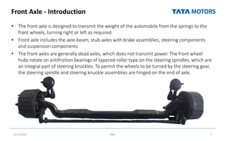
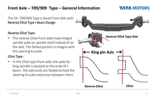
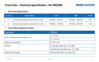
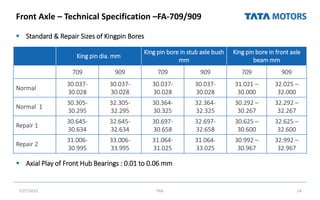
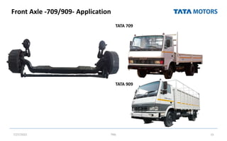
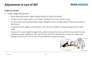
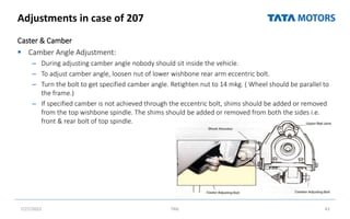
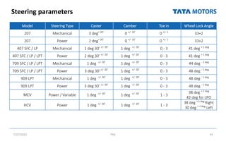
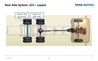
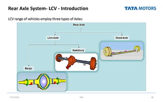
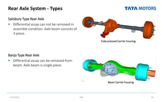
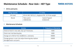
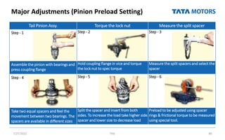
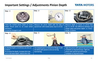
The document provides information on the front and rear axle systems for LCV vehicles. It discusses the objectives, agenda, and general information about the front axle 709/909 type. The document outlines the process for overhauling the front axle, including removal from the vehicle, inspection, and removal and assembly of wheel hub and stub axle components. It also discusses technical specifications, adjustments and settings for the front axle. For the rear axle, it provides information on the 407/709 type including removal, disassembly, inspection and reassembly processes.
This document provides an overview of the Technician Level 2 Module 5 training program which focuses on brake and suspension systems for LCV vehicles. The objectives are to understand S-cam air brake systems, perform inspections and overhauls of brake components, and understand hydraulic brake and suspension systems. The agenda covers S-cam brakes, hydraulic brakes, park brakes, and suspension systems.
The document provides information on steering system components for light commercial vehicles (LCVs) from Tata Motors. It discusses the objectives and agenda of the training module which focuses on overhauling three types of steering systems - ZF ball and nut type, rack and pinion type, and mechanical type. It also covers the construction, removal, installation, and diagnosis of the propeller shaft 709 type. Detailed information is given on recirculating ball and nut type steering systems, including mechanical and power assisted versions. The components and working of Rane brand recirculating ball steering gears are described.
The document provides information on overhauling transmission systems for LCV vehicles. It discusses dismantling and reassembling procedures for various gearboxes including the GBS-380, GBS-550, and TA-70 transaxle. The summary discusses the key components covered in the document:
1) The document covers overhauling procedures for various gearboxes used in Tata LCV vehicles including the GBS-380, GBS-550, and TA-70 transaxle.
2) Dismantling and reassembly procedures are provided for each transmission system as well as inspections of individual components and the use of special tools.
3) Information is given on removing the transmissions
The document discusses various components that connect the transmission to the drive wheels, including the propeller shaft, universal joints, constant velocity joints, and slip joints. It provides details on the construction and function of each component. The propeller shaft transmits power from the transmission to the rear differential. Universal joints and constant velocity joints allow the shaft to transmit power through varying angles, while slip joints allow adjustments to the shaft length during vehicle movement.
The document provides instructions for troubleshooting and repairing steering issues. It describes how to check for issues with various steering system components like the steering column, steering gear housing, and tie rod ends. The steps include how to disassemble, inspect, and replace parts as needed. Proper tooling is listed to facilitate repairs. Care must be taken when working on steering components as it affects vehicle handling.
This document discusses the main components of automotive disc brakes, including the mounting bracket, rotor, caliper, and pads. It describes the purpose and basic operation of each part. The rotor comes in vented and non-vented varieties and can require repair work like truing. Calipers are either fixed or floating and contain pistons and seals. Disc brakes are self-adjusting, and wear indicators help detect when pads need replacement. Common brake issues like noise, pulsation, and excessive pedal travel are also briefly mentioned.
The document provides information on rear axle drives and rear axle shafts. It discusses the Hotchkiss drive system which uses leaf springs to locate the rear axle and transmit driving forces. It is a simple and inexpensive design. The document also describes torque tube drives and compares them to Hotchkiss drives. Finally, it discusses different types of rear axle shafts including semi-floating, full-floating, and three-quarter floating axles.
The document discusses the steering system of vehicles. It describes the steering system as the interface between the driver and vehicle that allows the driver to guide the vehicle by controlling the path. It converts rotational motion of the steering wheel into angular turns of the wheels. Factors like steering ratio, geometry, power steering determine the steering effort required and turning radius. Proper alignment of components like caster, camber, toe is important for steering stability and reducing tire wear.
This document discusses the steering system of vehicles. It describes the main components of a conventional linkage steering system, including the steering wheel, steering column, steering shaft, steering gearbox, pitman arm, drag link, tie rods, and knuckle arm. It also covers steering geometry concepts such as camber angle, king pin inclination, included angle, and caster angle. The steering system is designed to allow the vehicle to follow the desired path by controlling the direction of the front wheels via the hand-operated steering wheel.
The document discusses various types of automotive braking systems. It describes the principles of hydraulic brakes, which use fluid pressure to provide equal braking force to all wheels according to Pascal's law. Drum brakes are also summarized, noting how brake shoes expand outward to contact the rotating drum and slow the wheels. Disc brakes are outlined as having pads that clamp onto a central disc attached to the wheel. Power brakes are mentioned as using engine vacuum pressure to boost braking force applied by the driver.
The document provides information about braking systems. It discusses the main functions of braking systems which are to stop the vehicle safely and control the vehicle when descending hills. It describes the two main types of braking system layouts - front/rear hydraulic split and diagonal split. It explains the components of braking systems including the brake pedal, master cylinder, brake lines, and discusses different types of braking systems such as mechanical, hydraulic, pneumatic, and discusses components like brake linings. It provides diagrams to illustrate hydraulic and mechanical braking systems.
The suspension system connects a vehicle to its wheels and serves two main purposes - contributing to handling and braking safety while also providing a comfortable ride by isolating the vehicle from road bumps and noise. An effective suspension balances these goals. Most modern vehicles use independent front and rear suspension systems with springs, shock absorbers, and linkages to enable each wheel to move independently without affecting the others, improving both ride and handling. The suspension aims to separate the energy of vertical wheel movements from the vehicle body.
This document is a seminar report on automatic transmission systems submitted by Vijay Kumar, an 8th semester mechanical engineering student at VVCE Mysore. It discusses the key components of automatic transmissions including planetary gear sets, hydraulic systems, torque converters, clutches, bands and computer controls. It also covers rear-wheel drive and front-wheel drive transmissions, common problems, and repair options. The conclusion emphasizes the importance of keeping transmissions and fluid at the proper operating temperature for long life. References include technical websites and manuals.
The document discusses different types of axles used in vehicles. It describes front axles which support the front of the vehicle and facilitate steering. Front axles can be dead axles, which do not rotate, or live axles which transmit power to the front wheels. Rear axles support the weight of the vehicle and transmit driving thrust. The document outlines full-floating, semi-floating, and three-quarter floating rear axles and how they differ in how they carry weight and transmit torque. It also discusses stub axles which connect to the front axle and allow the front wheels to turn for steering.
The document provides an overview of power steering systems. It discusses the history of power steering from its invention in the early 1900s to its use in automobiles and agricultural vehicles. The key components of power steering systems are described including the reservoir, steering gearbox, rotary valve, and pump. The main types of power steering systems - hydraulic, electro-hydraulic, and electric - are outlined along with diagrams of how each system works. Advantages like reduced driver fatigue and continuous steering are balanced with potential disadvantages such as leakage and vibration.
The document discusses three types of rear axle casings: 1) Split type which has two halves bolted together and requires removing the entire rear axle for repairs; 2) Banjo or separate carrier type which has a one-piece casing that carries the differential unit and allows removing half shafts for repairs; and 3) Salisbury or integral carrier type which is like the banjo type but has permanent housing tubes welded to the differential housing, making it the most widely used type today.
Design,Analysis & Fabrication of suspension of all terrain vehicleZubair Ahmed
This document provides an overview of suspension systems for vehicles, including definitions of key terms. It focuses on designing the suspension system for an all-terrain BAJA vehicle. The document discusses dependent and independent suspension systems. For the BAJA vehicle, an independent suspension was selected. The design process involved selecting components, geometry, and simulation to optimize ride, handling, and other factors. Detailed design of front and rear suspension components is described, including wishbones, uprights, wheel hubs, stub axles, trailing arms, and more. Steering system design is also discussed.
Frame and Body of Automobile
Introduction to chassis, Classification of chassis, Conventional chassis,
Semi forward chassis, Full forward chassis, Engine at the front, Engine at the rear, Engine in mid, Frame of the automobile, Function of Frame, types of frame, conventional frame, semi-integral frame, integral frame, defects in chassis, Body of the automobile, types of the body in automobile,
The document summarizes the components and operation of an automobile brake system. It describes the basic components including the caliper, caliper bracket, brake pads, rotors, and how hydraulic pressure is transferred through the system to create friction between the pads and rotors to slow the wheels. It then provides more detail on individual components like wheel knuckles, caliper pins, and pad retainers. It explains how kinetic energy from the moving rotor is transferred into thermal energy through friction to slow the car. In conclusion, it discusses the global, economic, and environmental impacts of brake system production and operation.
Tyres have several key functions: providing contact with the road surface, acting as the primary suspension, and allowing vehicles to brake, accelerate and steer. They are made up of plies, beads, treads and sidewalls. Radial tyres have plies that run straight across from bead to bead, providing a stable footprint. Proper tyre pressure and tread depth are important to prevent aquaplaning, where a layer of water builds up between the tyre and road surface causing loss of traction.
This document discusses various components and classifications of vehicle suspension systems. It describes common suspension links like control arms, radius rods, and trailing arms. It explains suspension types such as double wishbone, MacPherson strut, swing axle, live axle with leaf springs, and de Dion tube suspensions. It also covers rear suspension configurations including live-axle with coil springs and independent rear suspension with shocks. In summary, the document provides an overview of key suspension links and classifications of front and rear suspension designs used in automobiles.
The propeller shaft transmits power from the gear box to the differential through universal joints on each end, allowing the rear wheels to rotate. It is a steel tube that can withstand high torsional stresses and vibrations from transferring the rotary motion of the main transmission shaft to the differential. A slip joint is included to account for any axial movement of the propeller shaft during operation.
Drive shafts come in one-piece and two-piece designs, with two-piece used for longer wheelbases and including a center support bearing. Universal joints attach drive shafts to the transmission slip yoke end and rear axle flange end. Constant velocity joints in front-wheel drive vehicles and independent rear suspension vehicles allow for angular velocity differences between the drive shaft and the driven parts. Transfer cases are used on 4-wheel drive vehicles to connect both drive shafts together and can include part-time locking hubs to engage the front wheels through vacuum or electrically-powered solenoids.
The suspension System of an automobile is one which separates the wheel/axle assembly from the body. The primary function of the suspension system is to isolate the vehicle structure from shocks & vibration due to irregularities of the road surface.
Bearing Description about basic, types, failure causesPankaj
This document discusses different types of bearings. It begins by defining a bearing as a device that allows constrained relative motion between two parts, typically rotation or linear movement. It then classifies bearings based on the motions they allow and their principle of operation. The document goes on to describe various types of bearings in detail, including ball bearings, roller bearings, thrust bearings, tapered roller bearings, and cylindrical roller bearings. It provides information on the characteristics, advantages, applications, and physical features of each bearing type.
Gears are used to transmit motion or power from one shaft to another. There are several types of gears classified by their relative position of axes, velocity, type of gearing, and position of teeth. The main types discussed are spur gears, which have parallel teeth and axis and are used to transmit power between parallel shafts, helical gears which have teeth cut at an angle for smoother operation, rack and pinion gears which convert rotational to linear motion, bevel gears which change the direction of rotation by 90 degrees, and worm gears which transfer motion between non-parallel shafts. Spur gear terminology includes features like the top land, bottom land, face, flank, addendum, dedendum, space width
The document discusses various types of automobile suspension systems. It describes independent suspension systems that allow each wheel to move independently and non-independent systems where the wheels are attached to a solid axle. Common types of independent suspension include MacPherson strut suspension, wishbone suspension, and solid rear axle suspension. The document also covers suspension components like springs, shock absorbers, control arms, and sway bars. It provides advantages and disadvantages of different suspension types.
This document provides information about the steering system of an automobile. It discusses various components and angles of the steering system including camber, caster, king pin inclination, and toe-in/toe-out. It describes the functions of these components such as maintaining stability and returning the wheels to straight ahead position after a turn. The document is a report submitted by engineering students for their subject on automobile engineering focusing on the steering system.
Caterpillar cat 955 k track loader (prefix 71j) service repair manual (71j045...uudujjfjskkkdm
This document provides instructions for servicing the power train of a Caterpillar 955K track loader, including:
- Checking and adjusting the alignment between the engine and transmission.
- Removing and installing the transmission, torque converter, and various transmission components.
- Disassembling and assembling the planetary transmission and torque converter.
- Servicing the transmission hydraulic controls, lubrication system, and mounting adapter.
Detailed step-by-step instructions and diagrams are provided for servicing each component. Tolerances and specifications are given for checking alignments.
Caterpillar cat 955 k track loader (prefix 71j) service repair manual (71j045...udfjjjskekdme
This document provides instructions for servicing the power train of a Caterpillar 955K track loader, including:
- Checking and adjusting the alignment between the engine and transmission.
- Removing and installing the transmission, torque converter, and various transmission components.
- Disassembling and assembling the planetary transmission and torque converter.
- Servicing the transmission hydraulic controls, lubrication system, and mounting adapter.
Detailed step-by-step instructions and diagrams are provided for servicing each component. Tolerances and specifications are given for checking alignments.
Caterpillar cat 955 k track loader (prefix 71j) service repair manual (71j045...fjjskkdmnsme
This document provides instructions for servicing the power train of a Caterpillar 955K track loader, including:
- Checking and adjusting the alignment between the engine and transmission.
- Removing and installing the transmission, torque converter, and various transmission components.
- Disassembling and reassembling the planetary transmission and torque converter.
- Servicing the transmission hydraulic controls, lubrication system, and mounting adapter.
Detailed steps and diagrams are included to guide the disassembly and reassembly of the power train components. Safety precautions and specifications are provided where relevant.
Caterpillar cat 955 k track loader (prefix 71j) service repair manual (71j045...fjjsefkksemme
This document provides instructions for servicing the power train of a Caterpillar 955K track loader, including:
- Checking and adjusting the flexible coupling alignment between the engine and transmission.
- Removing and installing the transmission and torque converter.
- Disassembling and assembling the planetary transmission and torque converter.
- Removing and installing the transmission hydraulic and mechanical controls.
Detailed step-by-step instructions are given for accessing, removing, and installing each component, along with specifications for alignment checks and torque values for fasteners. Potential causes of misalignment are discussed.
Caterpillar cat 955 k track loader (prefix 71j) service repair manual (71j045...fujsjexswfksekmfm
This document provides instructions for servicing the power train of a Caterpillar 955K track loader, including:
- Checking and adjusting the alignment between the engine and transmission.
- Removing and installing the transmission, torque converter, and various transmission components.
- Disassembling and assembling the planetary transmission and torque converter.
- Servicing the transmission hydraulic controls, lubrication system, and mounting adapter.
Detailed step-by-step instructions and diagrams are provided for servicing each component. Tolerances and specifications are given for checking alignments.
Caterpillar cat 955 k track loader (prefix 71j) service repair manual (71j045...fjskekmsemmwe
This document provides instructions for servicing the power train of a Caterpillar 955K track loader, including:
- Checking and adjusting the alignment between the engine and transmission.
- Removing and installing the transmission, torque converter, and various transmission components.
- Disassembling and assembling the planetary transmission and torque converter.
- Servicing the transmission hydraulic controls, lubrication system, and mounting adapter.
Detailed step-by-step instructions and diagrams are provided for servicing each component. Torque specifications and special tools required are also listed.
The document provides instructions for maintenance of the motor and gearbox assemblies for an AMF 82/70 pinspotter, including identification of parts, disassembly, inspection, parts replacement, and reassembly. It describes the three main motor/gearbox units - the back-end motor and two combination motors. The back-end motor drives components like the carpet system and pin elevator. Proper maintenance following the outlined steps is important to ensure smooth operation.
Case ih 990 agricultural tractor service repair manualjfjkskekemm
The document provides information on servicing the front axle and steering components of Implematic tractors. It describes procedures for removing and installing front hubs, stub axles, the front axle, and the front extension on different tractor models. It also provides details on adjusting front wheel alignment, servicing steering boxes, power-assisted steering systems, and dimensions for bush mandrels. The document is intended as a service manual for mechanics repairing and maintaining the front axle and steering systems of Implematic tractors.
Induction training for Employees & Articles updated.pptxMeghanNagvekar
EAP is a growing CA firm in Navi Mumbai founded in 1980. The document provides an overview of EAP's history, growth, vision, policies and procedures. It summarizes EAP's core values of integrity and client focus. It also outlines some of EAP's HR policies related to attendance, leave, dress code, mobile usage and independence to maintain professional standards.
This document provides an overview of a training module on brake and suspension systems for light commercial vehicles. The module objectives are to understand S-cam air brake systems, perform inspections and repairs of brake components, and overhaul front and rear suspension systems. The agenda covers S-cam brakes, hydraulic brakes, hand brakes, and suspensions. It also details the components and operation of S-cam brake systems used on Tata vehicles.
The document provides information about an engine systems training module for technicians. It includes an introduction, program objectives, agenda, and details about various Tata LCV models and their engine systems. The key points covered are:
- The module will help technicians understand Tata's LCV range, identify different engine types used, state technical specifications, and perform engine overhaul and important settings.
- It covers product familiarization of various LCV models like 407, 709, 909, 207 DI, Xenon, and Winger.
- The technical specifications and features of different engines are explained, including the 4SPTC, 497 TCIC, and 483 DL TCIC engines.
This document provides an overview of electrical systems for technicians working on buses. It discusses the basic components of electrical circuits like the battery, wiring, switches and relays. It then explains the multiplexed wiring system used in modern vehicles and the benefits it provides like reduced wiring, improved reliability and easier diagnostics. The document reviews fuse box locations and covers the starting circuit, highlighting how multiplexing integrates the electronic control modules. Technicians are instructed to trace the current flow through the starting, charging and ignition circuits under guidance to understand these core electrical systems.
This document provides an overview of a training module on suspension and retarder systems for buses. The module objectives are to identify different suspension systems used in buses, perform inspection and maintenance on suspensions, and understand retarder systems. The program agenda covers Weveller suspension components and removal/installation, air suspension components and kneeling function, and retarder overview. Practical exercises are included to inspect Weveller suspension and adjust air suspension height.
Steering System & Propeller Shaft (2).pptxMeghanNagvekar
The document provides information about a training module on steering systems and propeller shafts for low floor buses. The module objectives are to identify parts, perform checks and maintenance, and troubleshoot steering systems and propeller shafts. It describes the components and functions of steering systems like rack and pinion, issues like steering adjustments and bleeding procedures. It also details the components, removal and installation of propeller shafts and common troubleshooting issues like vibration and premature wear.
The document provides an overview of a training module on axle systems. It introduces three types of low floor front axles - the ZF RL 85 A, Meritor FH 946, and ZF RL 75 E. For each axle, it details specifications, components, tightening torques, greasing points, and special tools. It outlines the objectives, agenda, and practical exercises which include disassembling and assembling axles, overhauling calipers, and inspecting components. The exercises are intended to teach technicians how to perform basic checks, preventive maintenance, and dismantling/assembling of axle systems.
This document provides an overview of a training module on transmission and clutch systems. The module objectives are to perform basic checks, maintenance, dismantling and assembly of transmissions and clutches. The agenda covers Allison automatic transmissions, ZF manual gearboxes, and clutch system overhauling. Preventive maintenance tips are provided for transmissions, including fluid level checks, fluid and filter changes. Components and operation of Allison transmissions are explained. Practical exercises include identifying gearbox components, checking fluid levels, and removing/refitting a gearbox.
Introduction to Buses & Engine Systems.pptxMeghanNagvekar
The document provides an introduction to Tata Motors buses and engine systems. It discusses the objectives of the training program which are to understand Tata bus models, CNG fuel systems, and maintenance of CNG engines. The agenda covers an introduction to rear-engine and front-engine buses, an overview of compressed natural gas (CNG) and gas engine terminology, and details on the Cummins 6B5.9G and 3.8/5.7 SGI CNG engine systems including specifications and maintenance.
Part 2 Deep Dive: Navigating the 2024 Slowdownjeffkluth1
Introduction
The global retail industry has weathered numerous storms, with the financial crisis of 2008 serving as a poignant reminder of the sector's resilience and adaptability. However, as we navigate the complex landscape of 2024, retailers face a unique set of challenges that demand innovative strategies and a fundamental shift in mindset. This white paper contrasts the impact of the 2008 recession on the retail sector with the current headwinds retailers are grappling with, while offering a comprehensive roadmap for success in this new paradigm.
The 10 Most Influential Leaders Guiding Corporate Evolution, 2024.pdfthesiliconleaders
In the recent edition, The 10 Most Influential Leaders Guiding Corporate Evolution, 2024, The Silicon Leaders magazine gladly features Dejan Štancer, President of the Global Chamber of Business Leaders (GCBL), along with other leaders.
Building Your Employer Brand with Social MediaLuanWise
Presented at The Global HR Summit, 6th June 2024
In this keynote, Luan Wise will provide invaluable insights to elevate your employer brand on social media platforms including LinkedIn, Facebook, Instagram, X (formerly Twitter) and TikTok. You'll learn how compelling content can authentically showcase your company culture, values, and employee experiences to support your talent acquisition and retention objectives. Additionally, you'll understand the power of employee advocacy to amplify reach and engagement – helping to position your organization as an employer of choice in today's competitive talent landscape.
The Evolution and Impact of OTT Platforms: A Deep Dive into the Future of Ent...ABHILASH DUTTA
This presentation provides a thorough examination of Over-the-Top (OTT) platforms, focusing on their development and substantial influence on the entertainment industry, with a particular emphasis on the Indian market.We begin with an introduction to OTT platforms, defining them as streaming services that deliver content directly over the internet, bypassing traditional broadcast channels. These platforms offer a variety of content, including movies, TV shows, and original productions, allowing users to access content on-demand across multiple devices.The historical context covers the early days of streaming, starting with Netflix's inception in 1997 as a DVD rental service and its transition to streaming in 2007. The presentation also highlights India's television journey, from the launch of Doordarshan in 1959 to the introduction of Direct-to-Home (DTH) satellite television in 2000, which expanded viewing choices and set the stage for the rise of OTT platforms like Big Flix, Ditto TV, Sony LIV, Hotstar, and Netflix. The business models of OTT platforms are explored in detail. Subscription Video on Demand (SVOD) models, exemplified by Netflix and Amazon Prime Video, offer unlimited content access for a monthly fee. Transactional Video on Demand (TVOD) models, like iTunes and Sky Box Office, allow users to pay for individual pieces of content. Advertising-Based Video on Demand (AVOD) models, such as YouTube and Facebook Watch, provide free content supported by advertisements. Hybrid models combine elements of SVOD and AVOD, offering flexibility to cater to diverse audience preferences.
Content acquisition strategies are also discussed, highlighting the dual approach of purchasing broadcasting rights for existing films and TV shows and investing in original content production. This section underscores the importance of a robust content library in attracting and retaining subscribers.The presentation addresses the challenges faced by OTT platforms, including the unpredictability of content acquisition and audience preferences. It emphasizes the difficulty of balancing content investment with returns in a competitive market, the high costs associated with marketing, and the need for continuous innovation and adaptation to stay relevant.
The impact of OTT platforms on the Bollywood film industry is significant. The competition for viewers has led to a decrease in cinema ticket sales, affecting the revenue of Bollywood films that traditionally rely on theatrical releases. Additionally, OTT platforms now pay less for film rights due to the uncertain success of films in cinemas.
Looking ahead, the future of OTT in India appears promising. The market is expected to grow by 20% annually, reaching a value of ₹1200 billion by the end of the decade. The increasing availability of affordable smartphones and internet access will drive this growth, making OTT platforms a primary source of entertainment for many viewers.
B2B payments are rapidly changing. Find out the 5 key questions you need to be asking yourself to be sure you are mastering B2B payments today. Learn more at www.BlueSnap.com.
SATTA MATKA SATTA FAST RESULT KALYAN TOP MATKA RESULT KALYAN SATTA MATKA FAST RESULT MILAN RATAN RAJDHANI MAIN BAZAR MATKA FAST TIPS RESULT MATKA CHART JODI CHART PANEL CHART FREE FIX GAME SATTAMATKA ! MATKA MOBI SATTA 143 spboss.in TOP NO1 RESULT FULL RATE MATKA ONLINE GAME PLAY BY APP SPBOSS
Event Report - SAP Sapphire 2024 Orlando - lots of innovation and old challengesHolger Mueller
Holger Mueller of Constellation Research shares his key takeaways from SAP's Sapphire confernece, held in Orlando, June 3rd till 5th 2024, in the Orange Convention Center.
At Techbox Square, in Singapore, we're not just creative web designers and developers, we're the driving force behind your brand identity. Contact us today.
Structural Design Process: Step-by-Step Guide for BuildingsChandresh Chudasama
The structural design process is explained: Follow our step-by-step guide to understand building design intricacies and ensure structural integrity. Learn how to build wonderful buildings with the help of our detailed information. Learn how to create structures with durability and reliability and also gain insights on ways of managing structures.
2. Introduction
Participant Name
Dealership Name
Location
Experience in Tata Motors (In years & months)
Specialization in which Models / Aggregates
Hobbies
7/27/2022 TML 2
3. Program Objectives
At the end of this module the participants will be able to:
Understand the construction of Front & Rear Axle of LCV range of Vehicles
Perform Removal, Dismantle & Refitting of Front & Rear Axles of LCV Vehicles
Perform Overhauling of Rear Axle -407/709 Type
3
4. Program Agenda
Front Axle System
Front Axle -709 Type
– General Information
– Removal of Axle Components
– Disassembly of Axle Components
– Inspection
– Assembly of Axle Components
– Important Adjustments & Settings
Rear Axle System
Rear Axle -407/709 Type
– General Information
– Removal of Rear Axle
– Disassembly of Rear Axle
– Inspection and Checking of Components
– Assembling Crown Wheel & pinion
– Important Adjustments & Settings
7/27/2022 TML 4
5. (Front Axle & Rear Axle)
Introduction to Driveline & Axle Systems - LCV
7/27/2022 TML 5
7. Front Axle - Introduction
The front axle is designed to transmit the weight of the automobile from the springs to the
front wheels, turning right or left as required.
Front axle includes the axle-beam, stub-axles with brake assemblies, steering components
and suspension components
The front axles are generally dead axles, which does not transmit power. The front wheel
hubs rotate on antifriction bearings of tapered-roller type on the steering spindles, which are
an integral part of steering knuckles. To permit the wheels to be turned by the steering gear,
the steering spindle and steering knuckle assemblies are hinged on the end of axle.
7/27/2022 TML 7
8. Front Axle – 709/909 Type – General Information
The FA -709/909 Type is Dead Front Axle with
Reverse Elliot Type I Beam Design
Reverse Elliot Type:
The reverse Elliot front axles have hinged
spindle yoke on spindle itself instead of on
the axle. The forked portion is integral with
the steering knuckle.
Elliot Type :
In the Elliot type front axles the yoke for
king spindle is located on the ends of I-
beam. The axle ends are forked to hold the
steering knuckle extension between them
7/27/2022 TML 8
Reverse Elliot Elliot
Reverse Elliot Type Axle
11. Front Axle – Stub Axle Parts
7/27/2022 TML 11
Kingpin
Kingpin Bore
12. Front Axle – Technical Specification –FA-709/909
Technical Specification
7/27/2022 TML 12
Sl. No Description 709 909 Units
1
Stub axle parent bore for king pin
bush
35.031 – 34.969 37.031 – 36.969 mm
2 King pin bush outside diameter 35.076 – 35.060 37.076 – 37.060 mm
3
End play between & front axle
beam
0.025 – 0.10 0.025 – 0.10 mm
4
Shims for stub axle axial play,
available in thickness of
0.05, 0.10, 0.15, 0.5,
0.8, to 1.7 in steps of 0.1
mm
0.05, 0.10, 0.15, 0.5,
0.8, to 1.7 in steps of
0.1 mm
mm
5
Inner bearing seat diameter on
stub axle
54.990 – 54.977 54.990 – 54.977 mm
6
Outer bearing seat diameter on
stub axle
34.991 – 34.975 39.991 – 39.975 mm
13. Front Axle – Technical Specification –FA-709/909
Technical Specification
Front Wheel Alignment Data
7/27/2022 TML 13
Sl. No Description 709 909 Units
7 Inner bearing bore diameter on hub 94.962 – 94.922 99.962 – 99.927 mm
8 Outer bearing bore diameter on hub 79.968 – 79.938 89.962 – 89.927 mm
Description 709/909
Toe in (measured on wheel rim)
0 – 3 mm
0 – 25 mm
King pin inclination 9° 30’ + 10’
Caster For Power Steering - 3° ± 30
For Mechanical Steering - 1° ± 30
Wheel Lock Angle 48° for 709, 909, 712 and 912
14. Front Axle – Technical Specification –FA-709/909
Standard & Repair Sizes of Kingpin Bores
Axial Play of Front Hub Bearings : 0.01 to 0.06 mm
7/27/2022 TML 14
King pin dia. mm
King pin bore in stub axle bush
mm
King pin bore in front axle
beam mm
709 909 709 909 709 909
Normal
30.037-
30.028
30.037-
30.028
30.037-
30.028
30.037-
30.028
31.021 –
30.000
32.025 –
32.000
Normal 1
30.305-
30.295
32.305-
32.295
30.364-
30.325
32.364-
32.325
30.292 –
30.267
32.292 –
32.267
Repair 1
30.645-
30.634
32.645-
32.634
30.697-
30.658
32.697-
32.658
30.625 –
30.600
32.625 –
32.600
Repair 2
31.006-
30.995
33.006-
33.995
31.064-
31.025
31.064-
33.025
30.992 –
30.967
32.992 –
32.967
17. Removal of Front Axle from the Vehicle
Inspection of Front Axle
Removal of Front Axle – 709 Type from the Vehicle
7/27/2022 TML 17
Removal of Front Axle
from the Vehicle
– 709 Type
18. Removal of Front Brake Drum
Removal & Disassembly of Front Wheel Hub
Inspection of Brake Drum & Hub Components
Removal & Dis assembly of Stub Axle
Inspection, Assembly and Installation of Stub Axle
Please follow the reverse order of disassembly while
assembling/refitting the Axle Assembly on to the
Vehicle
Please Carry out Wheel Alignment as per the
Specification
Removal & Assembly of Wheel Hub & Stub Axle
Components
7/27/2022 TML 18
Removal & Assembly of
Wheel Hub & Stub Axle
Components-709 Type
19. Important Adjustments & Settings
Adjustment of Stub Axle Axial Play:
Place a magnetic stand on the axle beam
Measure end play between stub axle &
front axle beam end boss.
End Play can be reduced by increasing the
thickness of the adjusting shims and vice
versa
Select the correct shims to give an end play
as specified ( 0.025 to 0.010mm)
7/27/2022 TML 19
20. Adjustment of Front Hub Axial Play: All
7/27/2022 TML 20
Step - 1 Step - 2 Step - 3
Using torque, loose the lock nut. Using puller take out the hub.
Take out bearings and remove all
old grease, clean the bearing etc.
Step - 4 Step - 5 Step - 6
Measure shim of 2.5mm & set the
hub without grease, measure the
hub play by moving hub. Note and
take out hub.
Calculate new shims pack to achieve
specified hub play and re-install hub
with new shims and filling specific
qty of grease. Torque the lock nut.
Hub play to be measured &
adjusted using dial gauge with
special tool or magnetic stand and
dial gauge.
21. Front Axle Hub play integral hub with drum
(Magnetic Stand)
7/27/2022 TML 21
Step - 1 Step - 2 Step - 3
Open the cover and using special
tool take out split nut
Using special tool, take out hub
Take out bearings and remove all
old grease, clean the bearing etc.
Step - 4
Fit the bearing and hub on stub
axle using special tool
Measure hub play after fixing the magnetic stand of the dial gauge on
suitable mounting surface. Measure the hub play
24. Front Axle Shaft Removal- Spicer
7/27/2022 TML 24
• Put chocks at rear wheels
• Remove front wheels, disconnect brake hose, caliper assembly
• Release torsion bar load fully
• Disconnect tie rods
• Wrap axis shaft with layers of tape & use a wire to attach shaft to frame
• Disconnect top & bottom suspension ball joints
• Pry out with a big screw driver axle shaft at side gear end
• Remove wheel end with CV shaft after removing above wire
25. Removing the wheel end components
7/27/2022 TML 25
Separating wheel end from CV shaft
• Remove free running hub after removing Its fasteners
• Remove snap ring from axle shaft
• Remove washer & outer, inner brake assembly (hub lock components)
• Remove axle shaft
Caution: While loosening outer nut take care not to break pin on inner nut
Assembly of wheel end
• Torque Inner nut to 6.8 kg-m
• Rotate hub & back off inner nut 90 degrees maximum till pin on nut aligns with closest
hole In lock washer
• Torque outer nut to 20.3 to 30.5 kg-m
• Wheel bearing play should be 0.00 to 0.1 mm
26. Overhaul of spindle assembly
7/27/2022 TML 26
• Remove inner bearing from spindle using Adaptor ring (part no 2698 5890 3516), press (part no 2698 5890 3515)
and adaptor plug (part no 2704 5890 3329).
• Use adaptor (part no 2704 5890 3326) to remove bearing cage on spindle
• Remove the 6 nuts of brake dust shield and spindle
• Remove spindle from knuckle by tapping
• Remove spindle needle bearing and seal using Bearing puller (part no 2704 5890 3328)
27. Front Axle Shafts
7/27/2022 TML 27
RHS Shaft with male splines on DOJ
LHS Shaft with female splines on DOJ
• Each LH & RH half shaft has following 2 types of joints
• Fix Rzeppa joints : This is used on the wheel end
• Double offset joints (DOJ) : This is used near center section (differential)
• Rzeppa joint is built with arch grooved outer & inner race and a cage with 6 balls
• Arch grooves of the Rzeppa joint allow wheel up/down movement
• DOJ Is similar except with straight grooves to allow change in length
• LH half shaft fits onto axle shaft & RH Into differential side gears
28. Overhauling of Rzeppa Joint
7/27/2022 TML 28
Dismantling
• Mark position of small end of the boot on shaft for reassembly
• Cut & discard boot & clamp
• Clear grease to see snap ring of inner race
• Expand snap ring & remove shaft by topping on outer race
• Use ball assy. tool (part no 270458903333) to tilt inner race
from side to side in star pattern & remove all balls from the
cage
• Remove Inner race & cage
• Pivot inner race & remove from cage
Assembling
• On side of shaft having 1 circlip groove, fit boot & clamp (w/o
tightening)
• Reverse above assembly procedure
• Install new circlip in inner race
• Fully fill lithium grease
• Push CV joint onto shaft till 'click' of circlip Is heard -pull to
confirm
• Use clamp crimper (part no 270458903332) to clamp boot on
CV joint
• Align boot marks done at the 1st step and tighten clamp
29. Overhauling of Double Offset Joint
7/27/2022 TML 29
Dismantling
Mark position of boot for reassembly
Cut & discard boot & clamp
If grease Is contaminated, CV joints needs replacement
Clear grease to remove retainer ring In outer race using screw
driver
Remove outer race
Using pliers (part no 270458903331) expand & slide back the
Inside circlip
Remove outer circlip using plier 2704 5890 3330
Assembling
On side of shaft having 2 circlip grooves, fit boot & clamp (without
tightening)
Assemble inner race, cage & balls
Install inner race assembly & 2 types of new circlip on shaft
Pack 2/3rd of specified amount of grease in outer race &
remaining inside boot
Install outer race assembly over ball & cage assembly
Push back inner race with balls & install large retaining ring
Use crimper (part no 2704 5890 3332) to crimp clamp on CV joint
Align boot marks as 1st step and tighten clamps.
30. Winger Front Axle (Transaxle)
Dismantling and assembling process of
Winger
Step 1:
Winger is front wheel drive vehicle and
having drive shafts for driving front wheels.
Winger front stub axle bearing is fitted on
stub axle with double bearing arrangement
as shown.
Step 2:
Jack up the vehicle, remove the tyres.
7/27/2022 TML 30
31. Winger Front Axle (Transaxle)
Step - 3
Remove locking pin between CV shafts and
axle shafts. Use a small pin & tap out the
pin from the smaller hole side.
Step - 4
Support the brake disc suitably.
Remove steering ball joint assy. from front
hub.
Tilt the front stub axle , pull & remove the
CV shaft from transaxle shaft side & then
from hub.
Remove nylock nut & dismantle front hub
from lower wish bone.
7/27/2022 TML 31
32. Winger Front Axle (Transaxle)
Step - 5
Hold the front stub axle in vice suitably &
unscrew the brake disc mounting bolts.
Use 3 jaw puller & pull the stub axle up.
Press out the unitised bearing.
7/27/2022 TML 32
34. Adjustments in LCV / MCV Front Axle Toe-in
1. Place toe-in gauge in front of front wheels. Adjust height of toe-in gauge arms to center of
wheel on both sides. Now adjust toe-in gauge width such that pin on one arm and gauge
spindle on other touch edges of wheel rim.
2. In this position set gauge such that pointer reads zero (0). Mark both wheel rims with chalk
at the points where pin and gauge spindle have touched.
3. Pull out spindle on gauge and lock in end position. Remove toe in gauge.
4. Move vehicle forward until chalk marks are rotated by 1800(now chalk marks are at rear).
Place toe-in gauge behind front wheels. Do not readjust width of toe in gauge. Move
complete toe in gauge such that pin on one arm touches rim at the chalk mark.
5. Unlock gauge spindle and let it touch rim at other chalk mark. The pointer on RHS indicate
toe-out and on LHS toe-in as seen from front of the vehicle.
6. If toe-in does not correspond to specified value adjust length of tie-rod by loosening tie-rod
clamps at both ends.
7/27/2022 TML 34
36. Adjustments in LCV / MCV Front Axle Camber and
Caster Angle
Camber Angle:
Camber angle is not adjustable in rigid suspension axle. The correct setting of hub play gives
correct camber angle.
It is measured with the help of gauge as shown:
– Keep the wheels straight ahead position
– Adjust two arms at end of wheel rim and then mark A & B at opposite side on tyre.
– Note reading on St. Move the wheels 1800 and again note reading.
– Average of two readings will indicate caster angle
7/27/2022 TML 36
37. Adjustments in LCV / MCV Front Axle Camber and
Caster Angle
Caster Angle:
Caster angle is measured with the gauge shown in fig.
Keep wheels straight ahead position and note reading on N side.
Steer the wheels 200 out side and again note reading.
Difference between the two readings shows the caster angle.
Caster Plate is given at the bottom spring for caster angle.
7/27/2022 TML 37
38. Checking Caster, Camber & King Pin Inclination (KPI)
with magnetic type gauge
1. Park the vehicle, place front wheel straight on turn
table. Remove front hub cover.
2. Place the magnetic gauge in centre of the spindle
such that “0” level is indicated on sprit gauge.
3. Angle indicated by bubble on camber scale will
indicate camber angle of that wheel.
4. To check the caster angle and KPI, turn the front
wheel 200 outward. Set respective bubbles of
Caster and KPI scales at “0” position.
5. Turn the wheels 200 inward, reading on caster
and KPI scales as indicated by the air bubbles will
indicate caster angle and KPI of the that wheel.
6. If camber is incorrect, check and adjust hub play. If
caster is incorrect, adjust with the help of caster
plate.
7. If KPI or camber is incorrect even after adjustment
of hub play, check for bend in I beam.
7/27/2022 TML 38
39. Adjustments in case of Xenon
Camber Adjustment Shims
Adding shims reduces camber and vice
versa.
Caster Adjustment Shims
Adding Caster shims in rear side of top
wishbone reduces caster.
Adding Caster shims in front side of top
wishbone increases caster.
7/27/2022 TML 40
40. Adjustments in case of Xenon
Toe Adjustment
Toe in adjusted by varying the length of tie rods after loosening hex nuts.
7/27/2022 TML 41
Toe Adjustment
Steering Tie rod
41. Adjustments in case of 207
Caster & Camber
Caster Angle Adjustment:
– While adjusting camber angle nobody should sit inside the vehicle.
– To adjust castor angle loosen nut of lower wishbone Front arm eccentric bolt.
– Turn the bolt to get specified castor angle. Retighten nut to 14 mkg. (Wheel should be parallel to
the frame.)
– If specified caster angle is not achieved, then shims are added / removed to get desired caster
angle.
– To adjust the castor angle through shims, add or remove the shims only from one side of the top
wishbone spindle. Adding the shims at the rear side of the spindle will increase the castor and
adding the shims at the front side of the spindle will reduce the castor.
7/27/2022 TML 42
42. Adjustments in case of 207
Caster & Camber
Camber Angle Adjustment:
– During adjusting camber angle nobody should sit inside the vehicle.
– To adjust camber angle, loosen nut of lower wishbone rear arm eccentric bolt.
– Turn the bolt to get specified camber angle. Retighten nut to 14 mkg. ( Wheel should be parallel to
the frame.)
– If specified camber is not achieved through the eccentric bolt, shims should be added or removed
from the top wishbone spindle. The shims should be added or removed from both the sides i.e.
front & rear bolt of top spindle.
7/27/2022 TML 43
44. Do’s & Don’ts
1. Vehicle should be parked on flat surface during Wheel alignment checking & setting.
2. In case of abnormal tyre wear, hub play, brake grabbing and wheel alignment to be checked.
3. Always use special tools / machine for checking & servicing.
7/27/2022 TML 45
46. Rear Axle System- LCV – Layout
7/27/2022 TML 47
Tandem Axle
(No drive)
Banjo Live
Rear Axle
47. Rear Axle System- LCV - Introduction
LCV range of vehicles employ three types of Axles:
7/27/2022 TML 48
48. Rear Axle System - Types
Salisbury Type Rear Axle
Differential assay can not be removed in
assemble condition. Axle beam consists of
3 piece.
Banjo Type Rear Axle
Differential assay can be removed from
beam. Axle beam is single piece.
7/27/2022 TML 49
Tube pressed Carrier housing
Beam Carrier housing
49. Rear Axle System - Types
Semi Floating Axle
One hub bearing is on axle shaft & another
bearing on differential carries load and
transmit torque.
Full Floating Axle
Axle shaft does not carry load and only
transmits torque.
7/27/2022 TML 50
Semi Floating Axle
Axle shaft is free
Axle shaft
with bearing
50. Rear Axle System- Banjo Type
A Banjo Differential has the gear set built into a removable centre in the rear axle housing.
Note that the differential centre is held in the axle housing by a series of studs that look like
the drum tuning keys on a banjo.
Advantages:
– Easy of Repair , Replace & maintain
– More GVW of the Vehicle Because of More RAW
– Easy On Site Repair Work
7/27/2022 TML 51
51. Rear Axle System- Salisbury Type
A Salisbury Rear Axle solves the rotating center that Banjos have by placing the carrier
bearings in the axle housing rather than in the removable center.
The differential is built into the axle rather than into a removable section.
Advantages
– Low Cost
– Easy To Manufacture
Dis Advantages
– On site repair is difficult.
– Low Load Taking Capacities hence applicable to Low GVW Vehicles.
7/27/2022 TML 52
52. Rear Axle System- Application in LCV
7/27/2022 TML 53
Model
Axle Type
Dead Axle Spicer 407 RA 104 1009 1109 Type RA 1055 RA 1068
Winger
Xenon, 207 Di
1109
Ultra truck 912
Ultra truck 812
Ultra bus 9.6T, 8.5T
Ultra bus 7.5T
709/712
LP 909/912
LPK 909
SK 709
SFC / LP / LPT 407
56. Rear Axle System – LCV - General Information
7/27/2022 TML 57
Vehicle
model
Rear axle /Ratio
CW/P
Ratio
Oil Capacity Hub grease Hub Play Backlash Axle wt
Xenon/207
Salisbury type
Spicer
51/11 2.2 L No grease Inbuilt 0.12 - 0.2 mm max 95 kg
LP/LPT/SF
C 407 Turbo
/ EX -Twin
tyre/410
RA 407 Type
37/8 or
35/9 RA
104 type -
31/8
1.5 L 225 gms 0.01 - 0.08 0.2 - 0.26 227 kg
LP/LPT/
SFC 709
Turbo EX
RA 104
Salisbury
31/8 2.75 L 375 gms 0.04 - 0.1 0.24 - 0.30 287 kg
LPT/LP
1109 Turbo
Ex
RA 1009 Banjo
43/11
41/11
41/7
8.5 L 700 gms 0.02 - 0.04 0.21 - 0.27 460 kg
LP1512TC RA108 RR 41/7 8.5 L 450 gms 01 - 06 mm 0.21 - 0.27 mm 350 kg
SK1613/
2515/2518
RA-109RR 41/6 14 L 650 gms 0.04-0.12 0.28-0.34 679 kg
Ultra Truck RA 1068 34/7 4 L
CONSIST ENCY-3,
Y-3, SS 6805
375 gms
0.04-0.12 0.24-0.30 285 kg
57. Rear Axle Identification Number
7/27/2022 TML 58
752 01 1 YY 1 23401
Basic Model
Variation in Basic Model
Year of Production
Plant Location
CWTP Ratio
Sr. Number
Identification Description
752 Basic Model - 407
01 SFC Twin Tyre
1 Crown Wheel to Pinion Ratio 34/7
YY Model Year
1 Jamshedpur
23401 Serial Number of Production
61. Rear Axle Components – Types of Wheel Hubs
Hub with brake drum 407 Rear Hub 709
7/27/2022 TML 62
Lock nut Lock ring
62. Rear Axle System – RA 108 ( Ultra Truck)
This is a banjo type rear axle having the different type of carrier housing as shown. This is a
split type housing and pinion depth is set by adjusting the shims as shown.
Pinion bearing having set preload with spacer
7/27/2022 TML 63
63. Rear Axle System – Spicer ( 207 / Xenon)
7/27/2022 TML 64
Differential Assy
Axle shaft New HD Axle Axle shaft Old Axle Single Bearing
65. Dismantling and assembly of Xenon axle shaft
bearing
Follow the Steps
7/27/2022 TML 66
Unscrew nuts at brake anchor plate and remove the axle shaft
Remove the bearing cup using Puller slide hammer (part no 2658 5890 3507)
Remove snap ring near retainer ring
Remove retainer ring from axle shaft by drilling in it a 6.5 mm diameter hole till 5 mm depth
Use chisel to break the ring. Fit new ring while assembling
Use puller (part no 2698 5890 3521) to pull out inner race of axle shaft bearing. (Use same puller to press in the bearing)
Use workshop press to install the retainer ring. To confirm its seating, use filler gauge 0.038 mm which should not enter around diameter.
66. Dismantling and assembly of Xenon New HD axle
shaft
7/27/2022 TML 67
Shaft Holding Spanner
Shaft nut torque socket
266358903502
Spanner
250658900103
HUB BRG REMOVAL & PRESSING
TOOL 266358903501
Axle shaft hub brg. removal tool
266358903503
• Removal of Axle shaft Bearing
• Straighten the bent lock washer
into the nut
• Install locknut removal tool on
lock nut with socket and loosen
the nut. (Torque 45 Kgm)
• The Bearing should be replaced
with shaft
• LH shaft is having LH treads and
RH shaft is having RH threads for
lock washer.
• LH shaft is having groove on spigot
on shaft as shown in fig.
• Similar marking is made on
threaded nut.
• For removing of bearing holder
from shaft, install the puller on
shaft.
• Tight the 4 nuts and by rotating
handle of bearing puller remove
the bearing assy. from shaft.
• To remove the bearing from bearing
holder, put the bearing holder on
bottom locator.
• Install the drift and take out the
bearing using press.
• Note: Do not use the bearing again if
the grease is slipped out from
bearing.
• The bearing is sealed and no
lubrication is required.
67. Spicer Axle – Limited Slip Differential
A limited slip differential (LSD) or anti-spin is a type of traction aiding device that uses a
mechanical system that activates under centrifugal force to positively lock the left and right
spider gears together when one wheel spins a certain amount faster than the other. The LSD
performs like an open differential under “normal” conditions, and automatically transfers
torque to the wheel with better traction when conditions demand.
This system is similar to conventional differential, except that part of torque from ring gear is
transmitted through clutch packs between side gears and differential case. In case of wheel
slippage clutch pack opposite to slipping side, is activated by separating forces between
pinion mate and corresponding side gear. This increases torque delivered to non-slipping
wheel and vehicle begins to move.
7/27/2022 TML 68
Note: LSD feature gets
activated & deactivated
automatically. No driver
intervention is required.
68. Removal of LSD Differential Assembly
Follow the Steps
7/27/2022 TML 69
Remove the differential cover plate by unscrewing cover plate screws
Remove the differential bearing caps. While assembling, ensure that the mating letters stamped on carrier and housing
are matched
Mount spreader (part no 2698 5890 3517) to the housing to spread the housing
Use dial gauge to ensure that the carrier is not spread more than 0.58 mm
Pry out differential case from carrier
69. Overhauling of Limited Slip Differential
Follow the Steps
7/27/2022 TML 70
Remove differential cross shaft by removing locking pin
Install adapter plate of track lock tool 2699 5890 3501 in bottom side gear
Install threaded adapter of track lock tool into top side gear
Screw in threaded adapter till it Is centered into adapter plate by using small screw driver to prevent adapter from turning
Torque driving bar of track lock tool to collapse Belleville plates
Remove pinion mate spherical washers
Loosen driving bar to relieve tension on belliville plates
Remove pinion mate gears by suitably rotating pinion mate gears
Remove tools & side gears with clutch pack
70. Pinion Depth Adjustment (Alternate Method)
1. Remove the Oil seal from top with tool.
2. Take out the pinion bearings.
3. Remove bearing cup.
4. Place master block and measure height.
5. Select the shim as per table and mark on
pinion.
6. Install bearing cone, bearings with new
collapsible spacer and new seal.
7. Collapsible spacer creates pre load on
bearings after torque the nut.
7/27/2022 TML 71
Pinion Height
Shim Selection
Pinion Bearing
Cup Removal
Pinion Oil Seal
Removing
71. Crown Wheel Pinion Backlash Adjustment of LSD
7/27/2022 TML 72
• Differential casing without ring
gear.
• Side play of differential case
without ring gear = A
• Differential casing with ring gear.
• Side play of differential case with
ring gear = B.
• Put shims towards the
backside of ring gear = B mm
to B-0.125 mm.
• Put shims towards the teeth
side of ring gear = A-B+0.2
mm.
Backlash = 0.13 mm to 0.2 mm (maximum variation at 3 points = 0.08 mm)
72. Spicer – Backlash Adjustment
Backlash Adjustment
Total play observed (Without crown wheel) = A
Left hand play (With crown wheel) = B
Right hand play = (A-B) = C
– Suppose A = 1.75 (0.070”)
– B = 1.01 (0.040”)
– C = 1.75 – 1.01 = 0.74 (0.030”)
Backlash Calculations:
Ring Gear Side: Assemble shim pack to measurement B – 0.125 or B-0.005”
Opposite Side of Ring Gear
Assemble shim pack to measurement C. Add 0.20 mm or C+ 0.008” for differential bearing
preload & backlash.
7/27/2022 TML 73
74. Removal & Dismantling of Crown Wheel & Tail
Pinion Assembly
Inspection of Crown Wheel & Pinion Assembly
Removal, Dismantle, Inspection & Re-fitment of Rear
Axle Carrier Assembly – 407/709 Type
7/27/2022 TML 75
Removal, Dismantle,
Inspection & Re-fitment
of Rear Axle Carrier
Assembly – 407/709
Type
75. Assembly of Tail Pinion in the Housing
Assembly of Crown Wheel
Installation of Crown Wheel Assembly in to
Housing
SST Involved
Assembly & Installation of Crown Wheel & Pinion
Assembly – 407/709 Type
7/27/2022 TML 76
Assembly & Installation
of Crown Wheel &
Pinion Assembly –
407/709 Type
76. Rear Axle System – 407 Type –Technical Specification
7/27/2022 TML 77
Sl. No Description Value in mm
1 Rear Axle housing max. permissible bend 2
2 End play of axle shaft gears 0.025 to 0.10
3 Brass thrust washer (for axle shaft gears) available in thickness 1.95 to 2.25 in steps of 0.05
4 Maximum permissible lateral runout of crown wheel mounting face on diff case 0.06
5 Backlash between crown wheel & tail pinion 0.25 to 0.33
6 Pre-load on tail pinion bearings toe give a friction movement 14 to 30 cm.kg
7 Thickness of split ring for tail pinion 7.6 to 8.2 in step of 0.02 and 9.26
8 Permissible variation in tail pinion depth -0.1
9 Maximum permissible runout of axle shaft near neck and centre of shaft 0.7
10 Clearance between thrust pad and crown wheel 0.25
11 Hub Play 0.04 to 0.1
12 Hub Inner bearing mounting ore dia 124.952 / 124.912
13 Hub outer bearing mounting bore dia 109.959 /109.924
14 Axle beam inner bearing seat dia 69.980 / 69.967
15 Axle beam outer bearing seat dia 59.980 / 59.967
16 Pre-load on differential side bearings 0.02 to 0.04
77. Maintenance Schedule - Rear Axle – 407 Type
Oil & Lubricants:
Maintenance Schedule:
7/27/2022 TML 78
Filling Capacity 1.5 Litres.
Oil Used 85 W 140 / API GL 5, Anglamol 99; 6.5 % by weight
Brand Telco spirol Castrol Hypoid
HD85W140 B 85W140
Activity Frequency in Kilometres
Check oil level in rear axle, top up if necessary 5000
Check rear hub bearing play 5000
Change oil in RA for first 10,000 kms and every 40000
Change grease in rear hub adjust bearing play replace
damaged worn out parts
20000
79. Major Adjustments (Pinion Preload Setting)
7/27/2022 TML 80
Tail Pinion Assy. Torque the lock nut Measure the split spacer
Step - 1 Step - 2 Step - 3
Assemble the pinion with bearings and
press coupling flange
Hold coupling flange in vice and torque
the lock nut to spec torque
Measure the split spacers and select the
spacer
Step - 4 Step - 5 Step - 6
Take two equal spacers and feel the
movement between two bearings. The
spacers are available in different sizes
Split the spacer and insert from both
sides. To increase the load take higher side
spacer and lower size to decrease load
Preload to be adjusted using spacer
rings & frictional torque to be measured
using special tool.
80. Important Settings / Adjustments Pinion Depth
7/27/2022 TML 81
Step - 1 Step - 2 Step - 3
Check the marked pinion depth on crown
wheel. Ensure same no. on crown wheel
and pinion.
It must be changed in pair.
Measure the pinion depth with the help of
special tool with master piece. Say it is 55.62
Measure depth as shown on pinion face.
Say it is 54.09 the difference between tool
master piece and pinion depth. I.e. 55.62 –
54.09 = 0.53mm.
Step - 4 Step - 5 Step - 6
As Marked depth is 54.09 then set shim of
0.53mm.
To increase the depth, increase shim size
and to decrease depth, reduce shim size.
Use stepped jaws to hold pinion flange, it will
not allow split spacers to be out during
hammering.
Tight the pinion with special tool and torque
multiplier to required torque. Tight the
pinion with special tool and torque
multiplier to required torque.
81. Important Settings / Adjustments Backlash
7/27/2022 TML 82
Step - 7 Step - 8
• Ensure the LHS and RHS side differential bearings and caps are
fitted.
• Set the crown wheel and tight the plumber block bolt with 3 Kgm
torque. Set the crown wheel with 0.5 to 1 mm.
• Ensure threaded ring movement after fitment.
• Tight both the threaded ring at the same time revolve the assy.
• Insure the backlash should .5 to 1 mm
Step - 9 Step - 10
• Tighten the left threaded ring till the backlash should be 0.15
mm. Tighten the LH side bolt half of torque.
• Tight the RHS threaded ring to required backlash.
• Tight the both the side differential bolts to full torque and rotate
crown wheel and check the back lash at 4 places.
82. Important Settings / Adjustments
7/27/2022 TML 83
Differential gear backlash Crown Wheel run out checking Thrust pad screw setting
Select specified equal size of washers
and place at both ends of sun gear.
Tight the differential and cover with
torque. Measure gear back lash with
filler. If not ok, open and change the
spacer width
Mount dial gauge with the help of
holder on housing to check lateral run
out of crown.
Max. permissible : 0.06 mm
Tighten the screw in the housing till the
thrust washer rests on the machined
surface of the of the crown wheel. Then
turn the screw back by 1/6th of a turn &
lock the check nut. Clearance of 0.25
mm between the face of the thrust pad
83. Adjustments- RA1068 Pinion Bearing Preload
7/27/2022 TML 84
Step - 1 Step - 2 Step - 3
Take out the cover of pinion bearing housing
with tool
Remove both the Pinion Bearing Check the size of shims and fit in between
bearing spacer
Step - 4 Step - 5
Put the pinion hsg. along with the bearing
outer races on the pinion with inner bearing
inner race
Check the preload on the bearings
After checking the preload, after the spacer ring in order to get a bearing preload of 30-60kg-
cm. (for more bearing preload select shim of lesser thickness)
84. Adjustments Pinion Depth For RA 1068)
7/27/2022 TML 85
Step - 1 Step - 2
• Check the marked pinion depth on crown wheel. Ensure same no. on
crown wheel and pinion.
• It must be changed in pair.
• Tail Pinion Depth
Measurement Tool.
Step - 3 Step - 4 Step - 5
• Measure the pinion depth with
the help of special tool and
calculate the difference
between tool master piece and
pinion depth
• Select correct size of shim,
marked depth is 89.00, actual
depth is 88.1.
• Add 0.9mm shim to achieve the
depth,
• Fit the pinion housing on
carrier housing with shims and
tighten bolts with torque.
85. Adjustments Backlash For RA 1068
7/27/2022 TML 86
Step - 6 Step - 7 Step - 8
• Set the crown wheel in housing
with LHS and RHS bearings.
• Torque the Plummer block bolts
and ensure free movement of
threaded ring.
• Check back lash at 4 places
• Torque the LHS bolt with half
torque value and set the Back
lash to 0.07 mm. Torque both
bolts and move crown wheel
till desired back lash value.
86. Ring Gear & Pinion Tooth Contact Pattern
Paint ring Gear teeth with a marking
compound on both the drive & coast side
Rotate the Ring Gear one complete
rotation in both direction while applying
load with a large screw driver or similar
tool between the carrier casting and
differential casing
Decreasing the backlash moves the ring
gear closer to the pinion
Increasing the backlash moves the ring
gear away from the pinion
7/27/2022 TML 87
87. Ring Gear & Pinion Tooth Contact Pattern
Pattern- A:
Normal or desirable pattern. The drive pattern
should be centred on the tooth. The coast
pattern should be centred on tooth, but may be
slightly towards toe. There should be some
clearance between pattern & the top of the
tooth.
Pattern-B:
Backlash Correct – Thinner pinion shim required
Pattern -C:
Backlash Correct- Thicker pinion shim required
Pattern -D:
Pinion position shim correct. Decrease Backlash
Pattern-E:
Pinion Position shim correct. Increase Backlash
7/27/2022 TML 88
88. Rear Hub Play Adjustments
Hub Play with spacer and shim :
Measure hub play after fixing the magnetic
stand of the dial gauge on suitable
mounting surface. Measure the hub play
For example, Let the shim pack is of 2.5
mm, let the initial hub play is 0.5 mm. The
required hub play will be 0.04mm. To get
correct shim size for hub play of 0.04 mm
the new shim pack will be (2.50 - 0.50 +
0.04) = 2.04 mm.
The recommended hub play is between
0.02 to 0.06 mm.
7/27/2022 TML 89
89. Hub Play Setting – RA 1068
7/27/2022 TML 90
Step - 1 Step - 2 Step - 3
Using torque, loose the lock nut. Using puller take out the hub.
Take out bearings and remove all
old grease, clean the bearing etc.
Step - 4 Step - 5 Step - 6
Measure shim of 2.5mm & set the
hub without grease, measure the
hub play by moving hub. Note and
take out hub.
Calculate new shims pack to achieve
specified hub play and re-install hub
with new shims and filling specific
qty of grease. Torque the lock nut.
Hub play to be measured &
adjusted using dial gauge with
special tool or magnetic stand and
dial gauge.
90. Important Setting / Adjustment Values
7/27/2022 TML 91
Settings 1109 / 1112 407 Ultra RA 109 RR
Back lash between Crown
Wheel & Tail Pinion
0.20 - 0.26 mm 0.20 - 0.26 mm 0.24 - 0.30 mm 0.28 - 0.34 mm
Crown Wheel Run Out 0.06 mm 0.06 mm 0.06 mm 0.06 mm
Hub Play 0.02 - 0.04 mm 0.01 - 0.03 mm 0.04 - 0.12 mm 0.04 - 0.12 mm
Preload on Tail Pinion bearing 30 - 60 cm-kg 5 - 20 cm-kg 30 - 60 kg-cm 15 - 36 cm-kg
Tail Pinion depth value etched on crown wheel
91. Dos & Don'ts for Rear Axles
Do's
Select shims for hub bearing spacer
without fixing oil seal and without packing
grease.
Ensure free play for the hub bearings as
per specification, preferably on the lower
range of the specification.
Always use dial gauge for setting hub free
play as feel method will always mislead.
Ensure preloading of differential side
bearings while adjusting crown wheel and
pinion backlash.
Don'ts
Do not wash the bearings, differential,
crown-wheel and pinion etc. in water or
kerosene.
Do not punch the bearing seat to increase
the interference of bearing inner race on
spindle.
Do not preload the hub bearings.
Do not over-fill grease in the hub. Over-
filling of grease will cause excessive
churning of grease thereby excessive heat
generation and grease melting.
Axle tubes should not be cambered. It will
affect the tyres life.
7/27/2022 TML 92