Download to read offline

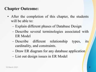

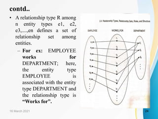
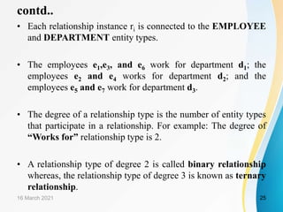
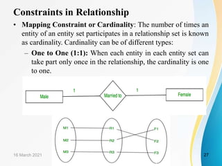
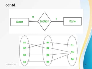
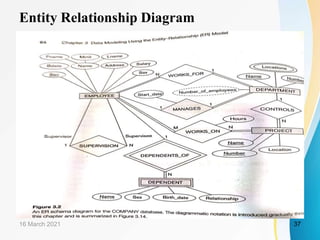
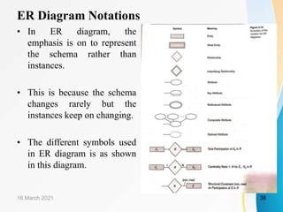
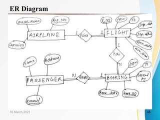
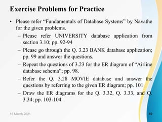

Chapter 3 of the document focuses on data modeling using the Entity-Relationship (ER) model in database management systems. It covers the phases of database design, the definitions and examples of entity types, relationship types, and attributes, as well as the constraints and design issues faced in ER models. The chapter concludes with exercises and a refined conceptual design of a company database application that illustrates the discussed concepts.