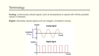
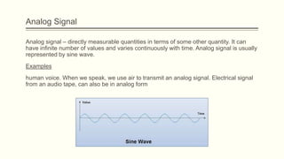
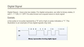
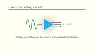
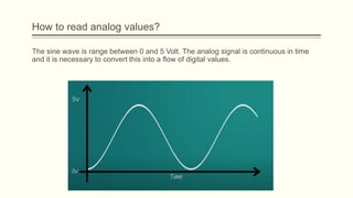
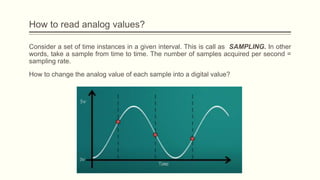
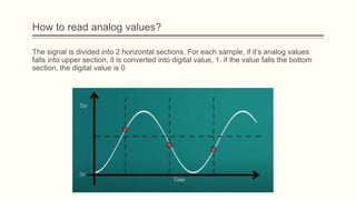
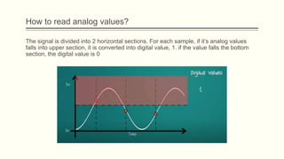
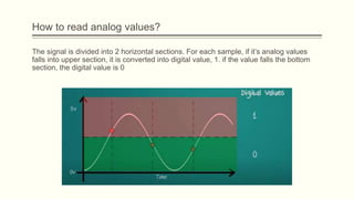
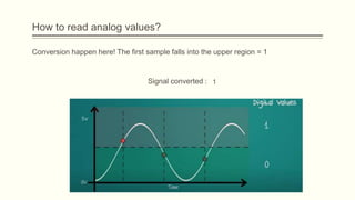
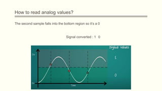
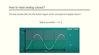
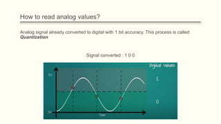
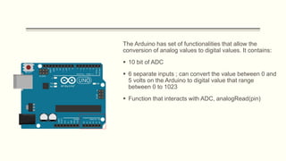
CONCEPT OF ANALOG VS DIGITAL IN
ARDUINO
Terminology
Analog: continuously valued signal, such as temperature or speed with infinite possible
values in between.
Digital: discretely valued signal such as integers, encoded in binary
Analog Signal
Analog signal – directly measurable quantities in terms of some other quantity. It can
have infinite number of values and varies continuously with time. Analog signal is usually
represented by sine wave.
Examples
human voice. When we speak, we use air to transmit an analog signal. Electrical signal
from an audio tape, can also be in analog form
Digital Signal
Digital Signal – have only two states. For digital computers, we refer to binary states, 0
and 1. 1 = ON, 0 = OFF. It is also known as a square wave or clock signal
Example:
a low pulse or no pulse represents a "0" and a high or pulse indicates a "1". The
illustration is an example of how digital signals may look.
Analog-to-Digital Conversion Principle
 The basic principle of operation is to use the comparator principle to determine
whether to turn on bit of the binary number output
 It is typical for an ADC to use a Digital-to-Analog conversion (DAC) to determine one of
the inputs to the comparator.
 When we interface sensors to the microcontroller, the output of the sensor many of the
times is analog in nature. But microcontroller processes digital signals.
 Hence, we use ADC in between sensor and microcontroller. It converts an analog
signal into digital and gives it to the microcontroller. The function that you use to obtain
the value of an analog signal is analogRead(pin).
 The Arduino does not have a built-in digital-to-analog converter (DAC), but it can
pulse-width modulate (PWM) a digital signal to achieve some of the functions of an
analog output. The function used to output a PWM signal is analogWrite(pin, value).
Analog-to-Digital Conversion Principle
These logical values are nothing more than a signal can only assume 0V and a max
voltage which is 5V
Although the Arduino can read and write these digital signals , not all devices work with
digital logic.
Potentiometer. It is manually adjustable variable resistor that acts as a variable voltage
divider.
Example, reading the values from a pot. It can be control the output voltage of
potentiometer by changing the knob position. The pot can be vary from 0 up to 1023
reading value.
Analog-to-Digital Conversion Principle
Analog Components
How to read analog values?
ADC is a piece of hardware that converts analog values to digital values.
The sine wave is range between 0 and 5 Volt. The analog signal is continuous in time
and it is necessary to convert this into a flow of digital values.
How to read analog values?
Consider a set of time instances in a given interval. This is call as SAMPLING. In other
words, take a sample from time to time. The number of samples acquired per second =
sampling rate.
How to change the analog value of each sample into a digital value?
How to read analog values?
The signal is divided into 2 horizontal sections. For each sample, if it’s analog values
falls into upper section, it is converted into digital value, 1. if the value falls the bottom
section, the digital value is 0
How to read analog values?
The signal is divided into 2 horizontal sections. For each sample, if it’s analog values
falls into upper section, it is converted into digital value, 1. if the value falls the bottom
section, the digital value is 0
How to read analog values?
The signal is divided into 2 horizontal sections. For each sample, if it’s analog values
falls into upper section, it is converted into digital value, 1. if the value falls the bottom
section, the digital value is 0
How to read analog values?
The signal is divided into 2 horizontal sections. For each sample, if it’s analog values
falls into upper section, it is converted into digital value, 1. if the value falls the bottom
section, the digital value is 0
How to read analog values?
Conversion happen here! The first sample falls into the upper region = 1
Signal converted : 1
How to read analog values?
The second sample falls into the bottom region so it’s a 0
Signal converted : 1 0
How to read analog values?
The last sample falls into the bottom region which correspond to digital value 0
Signal converted : 1 0 0
How to read analog values?
Analog signal already converted to digital with 1 bit accuracy. This process is called
Quantization
Signal converted : 1 0 0
The Arduino has set of functionalities that allow the
conversion of analog values to digital values. It contains:
 10 bit of ADC
 6 separate inputs ; can convert the value between 0 and
5 volts on the Arduino to digital value that range
between 0 to 1023
 Function that interacts with ADC, analogRead(pin)
READING A POTENTIOMETER
Tutorial
Material needed:
Wiring connection
Code
Discussion
1. What is the maximum value of potentiometer when connected to 3.3V?
2. Discuss among your friends, why it happen?
3. What happen if change 3.3V to 5V? Discuss, what is the output result of maximum
value potentiometer and why it happen?
PULSE WIDTH MODULATION
(PWM)
Introduction
Pulse Width Modulation (PWM) is a digital technology that uses the amount of power
delivered to a device that can be changed. It generates analogue signals by using a
digital source. A PWM signal is basically a square wave which is switched between on
and off state. The duty cycle and frequency of a PWM signal determine its behavior.
Duty Cycle in PWM
The duty cycle of the PWM signal refers to the ratio of the time that the signal is in a
high(on) state over the total time it takes to complete one cycle. It is commonly
expressed as a percentage or a ratio.
Which pins of Arduino support PWM?
Not all pins of Arduino support PWM. On the Uno board, the pins are specifically marked
with a ~ symbol.
As can be seen from the picture, only pins 3,5,6,9,10 and
11 can support PWM. The frequency of the square wave
is 490 Hz (about 2 ms time period) on all pins except 5
and 6, on which it is 980 Hz (about 1s time period).
APPLICATION OF PWM
LED brightening followed by dimming
connect an LED to a PWM pin, and keep increasing the duty cycle on that pin, thereby
increasing the voltage on that pin. Thus, the LED will keep getting brighter, till the max
duty cycle (100) is reached. note that an 8-bit number is used to represent the duty
cycle. Thus, the duty cycle can vary from 0 to 255. Thus, the value of 255 corresponds to
duty cycle of 100%. 127 represents ~50% duty cycle, and so on.
circuit diagram
Code

Chapter 9.pptx

  • 1.
    CONCEPT OF ANALOGVS DIGITAL IN ARDUINO
  • 2.
    Terminology Analog: continuously valuedsignal, such as temperature or speed with infinite possible values in between. Digital: discretely valued signal such as integers, encoded in binary
  • 3.
    Analog Signal Analog signal– directly measurable quantities in terms of some other quantity. It can have infinite number of values and varies continuously with time. Analog signal is usually represented by sine wave. Examples human voice. When we speak, we use air to transmit an analog signal. Electrical signal from an audio tape, can also be in analog form
  • 4.
    Digital Signal Digital Signal– have only two states. For digital computers, we refer to binary states, 0 and 1. 1 = ON, 0 = OFF. It is also known as a square wave or clock signal Example: a low pulse or no pulse represents a "0" and a high or pulse indicates a "1". The illustration is an example of how digital signals may look.
  • 5.
    Analog-to-Digital Conversion Principle The basic principle of operation is to use the comparator principle to determine whether to turn on bit of the binary number output  It is typical for an ADC to use a Digital-to-Analog conversion (DAC) to determine one of the inputs to the comparator.  When we interface sensors to the microcontroller, the output of the sensor many of the times is analog in nature. But microcontroller processes digital signals.  Hence, we use ADC in between sensor and microcontroller. It converts an analog signal into digital and gives it to the microcontroller. The function that you use to obtain the value of an analog signal is analogRead(pin).  The Arduino does not have a built-in digital-to-analog converter (DAC), but it can pulse-width modulate (PWM) a digital signal to achieve some of the functions of an analog output. The function used to output a PWM signal is analogWrite(pin, value).
  • 6.
    Analog-to-Digital Conversion Principle Theselogical values are nothing more than a signal can only assume 0V and a max voltage which is 5V Although the Arduino can read and write these digital signals , not all devices work with digital logic.
  • 7.
    Potentiometer. It ismanually adjustable variable resistor that acts as a variable voltage divider. Example, reading the values from a pot. It can be control the output voltage of potentiometer by changing the knob position. The pot can be vary from 0 up to 1023 reading value. Analog-to-Digital Conversion Principle
  • 8.
  • 9.
    How to readanalog values? ADC is a piece of hardware that converts analog values to digital values.
  • 10.
    The sine waveis range between 0 and 5 Volt. The analog signal is continuous in time and it is necessary to convert this into a flow of digital values. How to read analog values?
  • 11.
    Consider a setof time instances in a given interval. This is call as SAMPLING. In other words, take a sample from time to time. The number of samples acquired per second = sampling rate. How to change the analog value of each sample into a digital value? How to read analog values?
  • 12.
    The signal isdivided into 2 horizontal sections. For each sample, if it’s analog values falls into upper section, it is converted into digital value, 1. if the value falls the bottom section, the digital value is 0 How to read analog values?
  • 13.
    The signal isdivided into 2 horizontal sections. For each sample, if it’s analog values falls into upper section, it is converted into digital value, 1. if the value falls the bottom section, the digital value is 0 How to read analog values?
  • 14.
    The signal isdivided into 2 horizontal sections. For each sample, if it’s analog values falls into upper section, it is converted into digital value, 1. if the value falls the bottom section, the digital value is 0 How to read analog values?
  • 15.
    The signal isdivided into 2 horizontal sections. For each sample, if it’s analog values falls into upper section, it is converted into digital value, 1. if the value falls the bottom section, the digital value is 0 How to read analog values?
  • 16.
    How to readanalog values? Conversion happen here! The first sample falls into the upper region = 1 Signal converted : 1
  • 17.
    How to readanalog values? The second sample falls into the bottom region so it’s a 0 Signal converted : 1 0
  • 18.
    How to readanalog values? The last sample falls into the bottom region which correspond to digital value 0 Signal converted : 1 0 0
  • 19.
    How to readanalog values? Analog signal already converted to digital with 1 bit accuracy. This process is called Quantization Signal converted : 1 0 0
  • 20.
    The Arduino hasset of functionalities that allow the conversion of analog values to digital values. It contains:  10 bit of ADC  6 separate inputs ; can convert the value between 0 and 5 volts on the Arduino to digital value that range between 0 to 1023  Function that interacts with ADC, analogRead(pin)
  • 21.
  • 22.
  • 23.
  • 24.
  • 25.
    Discussion 1. What isthe maximum value of potentiometer when connected to 3.3V? 2. Discuss among your friends, why it happen? 3. What happen if change 3.3V to 5V? Discuss, what is the output result of maximum value potentiometer and why it happen?
  • 26.
  • 27.
    Introduction Pulse Width Modulation(PWM) is a digital technology that uses the amount of power delivered to a device that can be changed. It generates analogue signals by using a digital source. A PWM signal is basically a square wave which is switched between on and off state. The duty cycle and frequency of a PWM signal determine its behavior.
  • 28.
    Duty Cycle inPWM The duty cycle of the PWM signal refers to the ratio of the time that the signal is in a high(on) state over the total time it takes to complete one cycle. It is commonly expressed as a percentage or a ratio.
  • 29.
    Which pins ofArduino support PWM? Not all pins of Arduino support PWM. On the Uno board, the pins are specifically marked with a ~ symbol. As can be seen from the picture, only pins 3,5,6,9,10 and 11 can support PWM. The frequency of the square wave is 490 Hz (about 2 ms time period) on all pins except 5 and 6, on which it is 980 Hz (about 1s time period).
  • 30.
  • 31.
    LED brightening followedby dimming connect an LED to a PWM pin, and keep increasing the duty cycle on that pin, thereby increasing the voltage on that pin. Thus, the LED will keep getting brighter, till the max duty cycle (100) is reached. note that an 8-bit number is used to represent the duty cycle. Thus, the duty cycle can vary from 0 to 255. Thus, the value of 255 corresponds to duty cycle of 100%. 127 represents ~50% duty cycle, and so on.
  • 32.
  • 33.

Editor's Notes

  • #2 NOTE: To change the image on this slide, select the picture and delete it. Then click the Pictures icon in the placeholder to insert your own image.