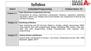
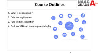
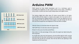
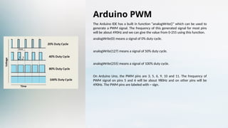
1
University Institute of Computing
Master of Computer Applications
Internet of Things (IoT)
Course Code: 23CAH-702
Designed By :
Dr. Kavita Jindal
Assistant Professor (ECE)
Syllabus
Unit-2 Embedded Programming Contact Hours: 15
Chapter 2.1
Basic Electronics Components and Laws
Introduction to various electronics components: Resistors, Capacitors, Inductors,
Transistors, Ohm’s Law, Voltage and Current Divider rule, Importance of Pull up and
Pull down resistors.
Chapter 2.2 Interfacing of Devices
Basic Interfacing and I/O Concept, Digital vs. Analog, voltage, denouncing, PWM
using Arduino Uno with programming. Digital: Interfacing LED, Switch, 7seg LED,
16x2 LCD with programming Analog: Potentiometer, LDR, Speaker, with
programming.
Chapter 2.3 Various Sensors and Devices
Control Units, Introduction to sensors : Gas Sensor, Temperature Sensor, LDR , RFID,
Bluetooth, ZigBee, Wi-Fi
3
1. What is Debouncing ?
2. Debouncing Reasons
3. Pule Width Modulation
4. Basics of LED and seven segment display
Course Outlines
Debouncing Push Buttons
When a push button is pressed, the electrical contacts can bounce,
causing the Arduino to register multiple, rapid button presses. This is
known as "debouncing" and needs to be addressed to ensure your
code responds correctly to user input. The solution is to add a short
delay after each button press to allow the contacts to settle.
In the Arduino code, you can achieve debouncing by tracking the last
time the button was pressed and only registering a new press if a
certain amount of time has elapsed. This prevents false triggers and
gives you reliable button input for your projects.
Arduino PWM
PWM stands for Pulse Width Modulation and it is a technique used in
controlling the brightness of LED, speed control of DC motor, controlling a
servo motor or where you have to get analog output with digital means.
The Arduino digital pins either gives 5V (when turned HIGH) or 0V (when
turned LOW) and the output is a square wave signal. So if we want to dim a
LED, we cannot get the voltage between 0 and 5V from the digital pin but we
can change the ON and OFF time of the signal. If we will change the ON and
OFF time fast enough then the brightness of the led will be changed.
TON (On Time): It is the time when the signal is high.
TOFF (Off Time): It is the time when the signal is low.
Period: It is the sum of on time and off time.
Duty Cycle: It is the percentage of time when the signal was high during the
time of period.
So at 50% duty cycle and 1Hz frequency, the led will be high for half a second
and will be low for the other half second. If we increase the frequency to 50Hz
(50 times ON and OFF per second), then the led will be seen glowing at half
brightness by the human eye.
Arduino PWM
The Arduino IDE has a built in function “analogWrite()” which can be used to
generate a PWM signal. The frequency of this generated signal for most pins
will be about 490Hz and we can give the value from 0-255 using this function.
analogWrite(0) means a signal of 0% duty cycle.
analogWrite(127) means a signal of 50% duty cycle.
analogWrite(255) means a signal of 100% duty cycle.
On Arduino Uno, the PWM pins are 3, 5, 6, 9, 10 and 11. The frequency of
PWM signal on pins 5 and 6 will be about 980Hz and on other pins will be
490Hz. The PWM pins are labeled with ~ sign.
Interfacing Push Buttons
Connecting a push button to an Arduino is straightforward. The button's two terminals are wired to
a digital input pin and ground. To detect when the button is pressed, the Arduino reads the state of
the input pin, which will be HIGH when the button is released and LOW when pressed.
Arduino Pin Button Terminal
Digital Input One Button Terminal
Ground Other Button Terminal
With this simple circuit, you can write Arduino code to detect button presses and trigger various
actions in your project, such as turning on an LED or advancing a counter.
Controlling LEDs
LEDs, or Light-Emitting Diodes, are a fundamental component in electronics and are easy to control
with an Arduino. By connecting an LED to a digital output pin on the Arduino, you can turn the LED
on and off, make it blink, or even fade it in and out to create various lighting effects.
The Arduino code to control an LED involves setting the digital output pin to HIGH to turn the LED
on, and LOW to turn it off. With a simple loop, you can create blinking patterns or fade the LED by
using the analogWrite() function to vary the brightness.
Seven-Segment Display
Basics
A seven-segment display is a visual electronic device used to display
numerical digits. It consists of seven LED segments arranged in a
specific pattern that, when selectively illuminated, can form the ten
digits (0-9) as well as some letters and symbols.
Interfacing a seven-segment display with an Arduino requires
connecting each segment to a digital output pin. By controlling the
state of these pins, the Arduino can light up the appropriate
segments to display the desired number or symbol. This allows you to
create numerical readouts, counters, and other digital displays in
your projects.
Driving Seven-Segment Displays
Common Anode vs.
Common Cathode
Seven-segment displays
come in two main
configurations: common
anode and common
cathode. The difference lies
in how the segments are
wired internally. For a
common anode display, the
positive terminal of each
segment is connected
together, while for a
common cathode display,
the negative terminal is
connected.
Controlling Segments
To light up a specific
segment, the Arduino must
apply a HIGH signal to the
corresponding output pin
for a common anode
display, or a LOW signal for
a common cathode display.
By carefully controlling the
state of all seven segment
pins, the Arduino can
display the desired digit or
symbol.
Multiplexing
For projects with multiple
seven-segment displays,
you can use a technique
called multiplexing to
reduce the number of
Arduino pins required. By
quickly switching between
the displays and
synchronizing the segment
control, the Arduino can
create the illusion of
multiple digits being
displayed at once.
Thankyou
Dr. Kavita Jindal

Lecture Notes 2.2.3 (Debouncing-Led-sevengement display) (1).pptx

  • 1.
    1 University Institute ofComputing Master of Computer Applications Internet of Things (IoT) Course Code: 23CAH-702 Designed By : Dr. Kavita Jindal Assistant Professor (ECE)
  • 2.
    Syllabus Unit-2 Embedded ProgrammingContact Hours: 15 Chapter 2.1 Basic Electronics Components and Laws Introduction to various electronics components: Resistors, Capacitors, Inductors, Transistors, Ohm’s Law, Voltage and Current Divider rule, Importance of Pull up and Pull down resistors. Chapter 2.2 Interfacing of Devices Basic Interfacing and I/O Concept, Digital vs. Analog, voltage, denouncing, PWM using Arduino Uno with programming. Digital: Interfacing LED, Switch, 7seg LED, 16x2 LCD with programming Analog: Potentiometer, LDR, Speaker, with programming. Chapter 2.3 Various Sensors and Devices Control Units, Introduction to sensors : Gas Sensor, Temperature Sensor, LDR , RFID, Bluetooth, ZigBee, Wi-Fi
  • 3.
    3 1. What isDebouncing ? 2. Debouncing Reasons 3. Pule Width Modulation 4. Basics of LED and seven segment display Course Outlines
  • 4.
    Debouncing Push Buttons Whena push button is pressed, the electrical contacts can bounce, causing the Arduino to register multiple, rapid button presses. This is known as "debouncing" and needs to be addressed to ensure your code responds correctly to user input. The solution is to add a short delay after each button press to allow the contacts to settle. In the Arduino code, you can achieve debouncing by tracking the last time the button was pressed and only registering a new press if a certain amount of time has elapsed. This prevents false triggers and gives you reliable button input for your projects.
  • 5.
    Arduino PWM PWM standsfor Pulse Width Modulation and it is a technique used in controlling the brightness of LED, speed control of DC motor, controlling a servo motor or where you have to get analog output with digital means. The Arduino digital pins either gives 5V (when turned HIGH) or 0V (when turned LOW) and the output is a square wave signal. So if we want to dim a LED, we cannot get the voltage between 0 and 5V from the digital pin but we can change the ON and OFF time of the signal. If we will change the ON and OFF time fast enough then the brightness of the led will be changed. TON (On Time): It is the time when the signal is high. TOFF (Off Time): It is the time when the signal is low. Period: It is the sum of on time and off time. Duty Cycle: It is the percentage of time when the signal was high during the time of period. So at 50% duty cycle and 1Hz frequency, the led will be high for half a second and will be low for the other half second. If we increase the frequency to 50Hz (50 times ON and OFF per second), then the led will be seen glowing at half brightness by the human eye.
  • 6.
    Arduino PWM The ArduinoIDE has a built in function “analogWrite()” which can be used to generate a PWM signal. The frequency of this generated signal for most pins will be about 490Hz and we can give the value from 0-255 using this function. analogWrite(0) means a signal of 0% duty cycle. analogWrite(127) means a signal of 50% duty cycle. analogWrite(255) means a signal of 100% duty cycle. On Arduino Uno, the PWM pins are 3, 5, 6, 9, 10 and 11. The frequency of PWM signal on pins 5 and 6 will be about 980Hz and on other pins will be 490Hz. The PWM pins are labeled with ~ sign.
  • 7.
    Interfacing Push Buttons Connectinga push button to an Arduino is straightforward. The button's two terminals are wired to a digital input pin and ground. To detect when the button is pressed, the Arduino reads the state of the input pin, which will be HIGH when the button is released and LOW when pressed. Arduino Pin Button Terminal Digital Input One Button Terminal Ground Other Button Terminal With this simple circuit, you can write Arduino code to detect button presses and trigger various actions in your project, such as turning on an LED or advancing a counter.
  • 8.
    Controlling LEDs LEDs, orLight-Emitting Diodes, are a fundamental component in electronics and are easy to control with an Arduino. By connecting an LED to a digital output pin on the Arduino, you can turn the LED on and off, make it blink, or even fade it in and out to create various lighting effects. The Arduino code to control an LED involves setting the digital output pin to HIGH to turn the LED on, and LOW to turn it off. With a simple loop, you can create blinking patterns or fade the LED by using the analogWrite() function to vary the brightness.
  • 9.
    Seven-Segment Display Basics A seven-segmentdisplay is a visual electronic device used to display numerical digits. It consists of seven LED segments arranged in a specific pattern that, when selectively illuminated, can form the ten digits (0-9) as well as some letters and symbols. Interfacing a seven-segment display with an Arduino requires connecting each segment to a digital output pin. By controlling the state of these pins, the Arduino can light up the appropriate segments to display the desired number or symbol. This allows you to create numerical readouts, counters, and other digital displays in your projects.
  • 10.
    Driving Seven-Segment Displays CommonAnode vs. Common Cathode Seven-segment displays come in two main configurations: common anode and common cathode. The difference lies in how the segments are wired internally. For a common anode display, the positive terminal of each segment is connected together, while for a common cathode display, the negative terminal is connected. Controlling Segments To light up a specific segment, the Arduino must apply a HIGH signal to the corresponding output pin for a common anode display, or a LOW signal for a common cathode display. By carefully controlling the state of all seven segment pins, the Arduino can display the desired digit or symbol. Multiplexing For projects with multiple seven-segment displays, you can use a technique called multiplexing to reduce the number of Arduino pins required. By quickly switching between the displays and synchronizing the segment control, the Arduino can create the illusion of multiple digits being displayed at once.
  • 11.