SlideShare a Scribd company logo
1 of 107
Chapter 4
Lenses and Optics
CONTENTS
4.1 Overview
4.2 Lens Functions and Properties
4.2.1 Focal Length and Field of View
4.2.1.1 Field-of-View Calculations
4.2.1.1.1 Tables for Scene Sizes vs.
FL for 1/4-, 1/3-, and
1/2-Inch Sensors
4.2.1.1.2 Tables for Angular FOV
vs. FL for 1/4-, 1/3-, and
1/2-Inch Sensor Sizes
4.2.1.2 Lens and Sensor Formats
4.2.2 Magnification
4.2.2.1 Lens–Camera Sensor Magnification
4.2.2.2 Monitor Magnification
4.2.2.3 Combined Camera and Monitor
Magnification
4.2.3 Calculating the Scene Size
4.2.3.1 Converting One Format to Another
4.2.4 Calculating Angular FOV
4.2.5 Lens Finder Kit
4.2.6 Optical Speed: f-number
4.2.7 Depth of Field
4.2.8 Manual and Automatic Iris
4.2.8.1 Manual Iris
4.2.8.2 Automatic-Iris Operation
4.2.9 Auto-Focus Lens
4.2.10 Stabilized Lens
4.3 Fixed Focal Length Lens
4.3.1 Wide-Angle Viewing
4.3.2 Narrow-Angle Telephoto Viewing
4.4 Vari-Focal Lens
4.5 Zoom Lens
4.5.1 Zooming
4.5.2 Lens Operation
4.5.3 Optical Speed
4.5.4 Configurations
4.5.5 Manual or Motorized
4.5.6 Adding a Pan/Tilt Mechanism
4.5.7 Preset Zoom and Focus
4.5.8 Electrical Connections
4.5.9 Initial Lens Focusing
4.5.10 Zoom Pinhole Lens
4.5.11 Zoom Lens–Camera Module
4.5.12 Zoom Lens Checklist
4.6 Pinhole Lens
4.6.1 Generic Pinhole Types
4.6.2 Sprinkler Head Pinhole
4.6.3 Mini-Pinhole
4.7 Special Lenses
4.7.1 Panoramic Lens—360�
4.7.2 Fiber-Optic and Bore Scope Optics
4.7.3 Bi-Focal, Tri-Focal Image Splitting Optics
4.7.4 Right-Angle Lens
4.7.5 Relay Lens
4.8 Comments, Checklist and Questions
4.9 Summary
4.1 OVERVIEW
The function of the camera lens is to collect the reflected
light from a scene and focus it onto a camera sensor.
Choosing the proper lens is very important, since its choice
determines the amount of light received by the camera
sensor, the FOV on the monitor, and the quality of the
image displayed. Understanding the characteristics of the
lenses available and following a step-by-step design proce-
dure simplifies the task and ensures an optimum design.
A CCTV lens functions like the human eye. Both col-
lect light reflected from a scene or emitted by a lumi-
nous light source and focus the object scene onto some
receptor—the retina or the camera sensor. The human
eye has a fixed-focal-length (FFL) lens and variable iris
71
72 CCTV Surveillance
diaphragm, which compares to an FFL, automatic-iris
video lens. The eye has an iris that opens and closes just
like an automatic-iris camera lens and automatically adapts
to changes in light level. The iris—whether in the eye or in
the camera—optimizes the light level reaching the recep-
tor, thereby providing the best possible image. The iris in
the eye is a muscle-controlled membrane; the automatic
iris in a video lens is a motorized device.
Of the many different kinds of lenses used in video secu-
rity applications the most common is the FFL lens, which
is available in wide-angle (90�), medium-angle (40�), and
narrow-angle (5�) FOVs. To cover a wide scene and also
obtain a close-up (telephoto) view with the same camera,
a variable-FOV vari-focal or zoom lens is used. The vari-
focal lens is used to “fine tune” the focal length (FL) to
a specific FL for the application. To further increase the
camera’s FOV a zoom lens mounted on a pan/tilt platform
is used.
The pinhole lens is used for covert video surveillance
applications since it has a small front diameter and can
easily be hidden. There are many other specialty lenses,
including split-image, fiber optic, right-angle, and auto-
matic focus.
A relatively new lens—the panoramic 360� lens—is used
to obtain a 360� horizontal by up to 90� vertical FOV. This
lens must be used with a digital computer and software
algorithm to make use of the donut-shaped image it pro-
duces on the camera sensor. The software converts the
image to a 360� panoramic display.
4.2 LENS FUNCTIONS AND PROPERTIES
A lens focuses an image of the scene onto the CCTV cam-
era sensor (Figure 4-1). The sensor can be a CCD, CMOS,
ICCD, or thermal IR imager.
The lens in a human and a camera have some similar-
ities: they both collect light and focus it onto a receptor
(Figure 4-2).
They have one important difference: the human lens
has one FFL and the retina is one size, but the camera
lens may have many different FLs and the sensor may
have different sizes. The unaided human eye is limited
to seeing a fixed and constant FOV, whereas the video
system can be modified to obtain a range of FOVs. The eye
has an automatic-iris diaphragm to optimize the light level
reaching the retina. The camera lens has an iris (either
manual or automatic) to control the light level reaching
the sensor (Figure 4-3).
HEIGHT
LENS FIELD
OF VIEW (FOV)
C OR CS
VIDEO OUT
POWER IN
V = VERTICAL HEIGHT
H = HORIZONTAL WIDTH
D = DIAGONAL
H × V = CAMERA SENSOR FOV
REFLECTED LIGHT FROM SENSOR
NATURAL OR ARTIFICIAL
ILLUMINATION SOURCE
CAMERA
D
WIDTH
MOUNT
SCENE VIEWED
BY CAMERA /LENS
V
H
CCD, CMOS, IR
SENSOR
LENS
FIGURE 4-1 CCTV camera/lens, scene, and source illumination
Lenses and Optics 73
CAMERA SENSOR
FIELD OF VIEW (FOV)
SCENE
EYE FIELD OF VIEW
EYE MAGNIFICATION = 1
EYE LENS FOCAL LENGTH ≈ 17 mm (0.67")
EYE RETINA
CAMERA SENSOR
LENS
IRIS
17 mm
SENSOR FORMAT
1/2"
1/3"
SCENE
1/4"
2/3"
FIGURE 4-2 Comparing the human eye to a CCTV lens and
camera sensor
EYE
AUTOMATIC IRIS
IRIS ALMOST CLOSED
WHEN VIEWING BRIGHT
SCENE (SUN)
IRIS HALF CLOSED
WHEN VIEWING NORMAL
SCENE (INDOORS)
IRIS WIDE OPEN
WHEN VEIWING DARK
SCENE (NIGHT TIME)
CCTV LENS
AUTOMATIC IRIS
MOTOR DRIVEN IRIS
DRIVE MOTOR/GEAR
MOTOR VIDEO
SIGNAL
METAL LEAVES
OPEN AND CLOSE
BY MOVING LENS
IRIS RING
IRIS OPEN
HALF CLOSED
IRIS NEARLY
CLOSED
DRIVE
FIGURE 4-3 Comparing the human eye and CCTV camera lens
iris
74 CCTV Surveillance
4.2.1 Focal Length and Field of View
In the human eye, magnification and FOV are set by the
lens FL and retina size. When the human eye and the
video camera lens and sensor see the same basic picture,
they are said to have the same FOV and magnification. In
practice, a lens that has an FL and FOV similar to that
of the human eye is referred to as a normal lens with a
magnification M = 1. The human eye’s focal length—the
distance from the center of the lens at the front of the
eye to the retina in the back of the eye—is about 17 mm
(0.67 inch) (Figure 4-2).
Most people see approximately the same FOV and mag-
nification (M = 1). Specifically, the video lens and cam-
era format corresponding to the M = 1 condition is a
25 mm FL lens on a 1-inch (diagonal) format camera, a
16 mm lens on a 2/3-inch format camera, a 12.5 mm lens
on a 1/2-inch camera, an 8 mm lens on a 1/3-inch cam-
era, and a 6 mm lens on a 1/4-inch sensor. The 1-inch
format designation was derived from the development of
the original vidicon television tube, which had a nom-
inal tube diameter of 1 inch (25.4 mm) and an actual
scanned area (active sensor size) of approximately 16 mm
in diameter. Figure 4-4 shows the FOV as seen with a lens
having magnifications of 1, 3, and 1/3 respectively.
Lenses with much shorter FL used with these sensors
are referred to as wide-angle lenses and lenses with much
longer FL are referred to as narrow-angle (telephoto)
lens. Between these two are medium FL lenses. Telephoto
lenses used with video cameras act like a telescope: they
magnify the image viewed, narrow the FOV, and effectively
bring the object of interest closer to the eye. While there
is no device similar to the telescope for the wide-angle
example, if there were, the device would broaden the FOV,
allowing the eye to see a wider scene than is normal and
at the same time causing objects to appear farther away
from the eye. One can see this condition when looking
through a telescope backwards. This also occurs with the
automobile passenger side-view mirror, a concave mirror
that causes the scene image to appear farther away, and
therefore smaller than it actually is (de-magnified).
Just as your own eyes have a specific FOV—the scene
you can see—so does the video camera. The camera FOV
is determined by the simple geometry shown in Figure 4-5.
The scene has a width (W ) and a height (H ) and is at a
distance (D) away from the camera lens. Once the scene has
been chosen, three factors determine the correct FL lens
to use: (1) the size of the scene (H� W ), (2) the distance
between the scene and camera lens (D), and (3) the camera
image sensor size (1/4-, 1/3-, or 1/2-inch format).
NORMAL
M = 1
WIDE
ANGLE
M = 1/3
NARROW
ANGLE
M = 3
MONITOR
MONITOR
MONITOR
FIGURE 4-4 Lens FOV for magnifications of 3, 1, and 1/3
Lenses and Optics 75
DIAGONAL(d ) HORIZONTAL(h) VERTICAL(v )
11 0.43 8.8 0.35 6.6 0.26
FORMAT
2/3"
1/2" 8 0.31 6.4 0.25 4.8 0.19
6 0.24 4.8 0.19 3.6 0.141/3"
inchmm mm mm inchinch
4 0.16 3.2 0.13 2.4 0.11/4"
1" 16 0.63 12.8 0.50 9.6 0.38
1/6" 3 0.12 2.4 0.09 1.8 0.07
LENS
VERTICAL HEIGHT
D = DISTANCE FROM SCENE
TO LENS
HORIZONTAL
WIDTH
CAMERA SENSOR
FOV
SOLID STATE
(CCD)
CAMERA
D
d
SENSOR SENSOR GEOMETRY
CCTV
SCENE
TUBE
d = DIAGONAL
W
H
VERTICAL = 3 UNITS HIGH
HORIZONTAL = 4 UNITS WIDE
v
h
v = VERTICAL
h = HORIZONTAL
SENSOR SIZE
FIGURE 4-5 Camera/lens sensor geometry and formats
4.2.1.1 Field-of-View Calculations
There are many tables, graphs, monographs, and linear
and circular slide rules for determining the angles and
sizes of a scene viewed at varying distances by a video
camera with a given sensor format and FL lens. One conve-
nient aid in the form of transparent circular scales, called
a “Lens Finder Kit,” eliminates the calculations required
to choose a video camera lens (Section 4.2.5). Such kits
are based on the simple geometry shown in Figure 4-6.
Since light travels in straight lines, the action of a lens
can be drawn on paper and easily understood. Bear in
mind that while commercial video lenses are constructed
from multiple lens elements, the single lens shown in
Figure 4-6 for the purpose of calculation has the same
effective FL as the video lens. By simple geometry, the
scene size viewed by the sensor is inversely proportional to
the lens FL. Shown in Figure 4-6 is a camera sensor of hor-
izontal width (h) and vertical height (v). For a 1/2-inch
CCD sensor, this would correspond to h = 6�4 mm and
v = 4�8 mm. The lens FL is the distance behind the lens at
which the image of a distant object (scene) would focus.
The figure shows the projected area of the sensor on the
scene at some distance D from the lens. Using the eye
analogy, the sensor and lens project a scene W wide × H
high (the eye sees a circle as did the original vidicon). As
with the human eye, the video lens inverts the image, but
the human brain and the electronics re-inverts the image
in the camera to provide an upright image. Figure 4-6
shows how to measure or calculate the scene size (W × H )
as detected by a rectangular video sensor format and lens
with horizontal and vertical angular FOVs �H and �V ,
respectively.
4.2.1.1.1 Tables for Scene Sizes vs. FL for 1/4-, 1/3-,
and 1/2-Inch Sensors
Tables 4-1, 4-2, and 4-3 give scene-size values for the 1/4-,
1/3-, and 1/2-inch sensors, respectively, as a function of
the distance from the camera to the object and the lens
FL. The tables include scene sizes for most available lenses
ranging from 2.1 to 150 mm FL.
To find the horizontal FOV �H, we use the geometry of
similar triangles:
h
W
= FL
D
� W = h
FL
× D (4-1)
The horizontal angular FOV �H is then derived as follows:
tan
�H
2
= h/2
FL
�H
2
= tan−1 h
2 FL
�H = 2 tan−1
h
2 FL
(4-2)
76 CCTV Surveillance
θV = VERTICAL ANGLE OF VIEW
H
SCENE
FIXED FOCAL
LENGTH LENS
CAMERA
SENSOR
FL
D
v = SENSOR VERTICAL HEIGHT
h = SENSOR HORIZONTAL WIDTH
h
v
W
H = SCENE HEIGHT
W = SCENE WIDTH
CAMERA LOCATION SCENE LOCATION
θH = HORIZONTAL
ANGLE OF VIEW
θH/2
θV/2
FIGURE 4-6 Sensor, lens and scene geometry
1/4 - INCH SENSOR FORMAT LENS GUIDE
CAMERA TO SCENE DISTANCE (D) IN FEET
WIDTH AND HEIGHT OF AREA (W × H ) IN FEET
5 10 20 30 40 50 75 100
LENS
FOCAL
LENGTH
(mm)
ANGULAR
FIELD OF
VIEW: H × V
(DEG.) W × H W × H W × H W × H W × H W × H W × H W ×
H
2.1 81.2 × 60.9 8.6 × 6.4 17 × 12.9 34 × 26 51 × 39 69 × 51 86
× 64 129 × 96 171 × 129
2.2 78.6 × 59.0 8.2 × 6.1 16.4 × 12.2 33 × 25 49 × 37 65 × 49
82 × 63 123 × 92 164 × 123
2.3 76.1 × 57.1 7.8 × 5.9 15.6 × 11.8 31 × 23 47 × 35 62 × 47
78 × 59 117 × 86 157 × 117
2.6 69.4 × 52 6.9 × 5.2 13.9 × 10.4 28 × 21 42 × 31 55 × 42 6 9
× 52 104 × 78 138 × 104
3.0 61.9 × 46.4 6.0 × 4.5 12 × 9 24 × 18 36 × 27 48 × 36 60 ×
45 90 × 68 120 × 90
3.6 53.1 × 39.8 5.0 × 3.8 10 × 7.5 20 × 15 30 × 23 40 × 30 50 ×
38 75 × 57 100 × 76
3.8 50.7 × 38.0 4.7 × 3.6 9.5 × 7.1 19 × 14 28 × 21 38 × 28 47 ×
36 71 × 54 94 × 72
4.0 48.5 × 36.4 4.5 × 3.4 9 × 6.8 18 × 14 27 × 20 36 × 27 45 ×
34 68 × 51 90 × 68
4.3 45.4 × 34.1 4.2 × 3.1 8.4 × 6.3 16.7 × 12.5 25 × 19 33 × 25
42 × 31 63 × 47 84 × 62
6.0 33.4 × 25.0 3 × 2.3 6 × 4.5 12 × 9 18 × 13.5 24 × 18 30 × 23
45 × 35 60 × 46
8.0 25.4 × 19.0 2.3 × 1.7 4.5 × 3.4 9 × 6.8 13.5 × 10.1 18 × 13.5
23 × 17 35 × 26 46 × 34
12.0 17.1 × 12.8 1.5 × 1.1 3 × 2.2 6 × 4.4 9.0 × 6.8 12 × 9 15 ×
11 23 × 17 30 × 23
16.0 12.8 × 9.6 1.1 × .8 2.3 × 1.7 4.5 × 3.4 6.8 × 5.1 9 × 6.8
11.2 × 8.4 17 × 13 22 × 17
25.0 8.2 × 6.2 .72 × .54 1.4 × 1.1 2.9 × 2.1 4.3 × 3.2 5.8 × 4.3
7.2 × 5.4 10.8 × 8.1 14.4 × 10.8
NOTE: 1/4 - INCH LENSES ARE DESIGNED FOR 1/4 - INCH
SENSOR FORMATS ONLY AND WILLNOT WORK ON
1/3 - INCH OR 1/2 - INCH SENSORS. LENS FOCAL
LENGTHS ARE NOMINAL PER MANUFACTURERS’
LITERATURE.
ANGULAR FOV AND W × H ARE DERIVED FROM
EQUATIONS 4 - 1 TO 4 - 4 AND VERTICAL FOV
FROM STANDARD 4:3 MONITOR RATIO: V =
0.75H.
Table 4-1 1/4-Inch Sensor FOV and Scene Sizes vs. FL and
Camera-to-Scene Distance
Lenses and Optics 77
1/3-INCH SENSOR FORMAT LENS GUIDE
5 10 20 30 40 50 75 100
LENS
FOCAL
LENGTH
(mm)
ANGULAR
FIELD OF
VIEW: H × V
(DEG.)
W × H W × H W × H W × H W × H W × H W × H W × H
92.4 × 69.3 10.4 × 7.8 20.8 × 15.6 41.6 ×3 1.2 63 × 47 83 × 62
104 × 78 156 × 117 208 × 156
85.4 × 64.1 9.2 × 6.9 18.5 × 13.8 36.8 × 27.6 55 × 41 77 × 58
92 × 69 138 × 104 184 × 138
81.2 × 60.9 8.6 × 6.5 17.2 × 13 34.4 × 26 51 × 39 69 × 52 86 ×
65 129 × 98 172 × 130
67.4 × 50.5 6.7 × 5.0 13.3 × 10 26.7 × 20 40 × 30 53 × 40 67 ×
50 101 × 75 134 × 100
64.6 × 48.4 6.3 × 4.7 12.6 × 9.5 25 × 18.9 37.9 × 28.4 50.5 ×
37.9 63 × 47 95 × 71 123 × 92
61.9 × 46.4 6.0 × 4.5 12 × 9 24 × 18 36 × 27 48 × 36 60 × 45 90
× 68 120 × 90
56.1 × 42.1 5.3 × 4.0 10.6 × 8 21.2 × 15.9 31.8 × 23.9 42.4 ×
31.8 53 × 40 80 × 60 106 × 80
43.6 × 32.7 4.0 × 3.0 8.0 × 6 16 × 12 24 × 18 32 × 24 40 × 30
60 × 45 80 × 60
33.4 × 25.0 3.0 × 2.3 6 × 4.5 12 × 9 18 × 13.5 24 × 18 30 × 22 .5
45 × 34 60 × 45
26.6 × 20.0 2.0 × 1.5 4.0 × 3.0 8.0 × 6.0 12.0 × 9.0 16 × 12 20 ×
15 30 × 23 40 × 30
17.1 × 12.8 1.5 × 1.2 3.0 × 2.3 6.0 × 4.5 9.0 × 6.8 12.0 × 9.0
15.0 × 11.3 23 × 17 30 × 22.5
11.0 × 8.2 .96 × .72 1.9 × 1.4 3.8 × 2.9 5.8 × 4.4 7.7 × 5.8 9.6 ×
7.2 14.4 × 10.8 19.2 × 14.4
5.5 × 4.1 .48 × .36 .96 × .72 1.9 × 1.4 2.9 × 2.2 3.8 × 2.8 4.8 ×
3.6 7.2 × 5.4 9.6 × 7.2
2.3
2.6
2.8
3.6
3.8
4.0
4.5
6.0
8.0
12.0
16.0
25.0
50.0
75.0 3.7 × 2.8 .32 × .24 .64 × .50 1.3 × .96 1.9 × 1.4 2.6 × 1.9
3.2 × 2.4 4.8 × 3.6 6.4 × 4.8
NOTE: MOST 1/3 - INCH LENSES WILL NOT WORK ON 1/2
- INCH SENSORS BUT ALL WILL WORK ON ALL 1/4 -
INCH SENSORS.
LENS FOCAL LENGTHS ARE NOMINAL PER
MANUFACTURERS’ LITERATURE.
ANGULAR FOV AND W × H ARE DERIVED FROM
EQUATIONS 4 - 1 TO 4 - 4 AND VERTICAL FOV FROM
STANDARD 4:3 MONITOR
RATIO: V = 0.75H.
CAMERA TO SCENE DISTANCE (D) IN FEET
WIDTH AND HEIGHT OF AREA (W × H ) IN FEET
Table 4-2 1/3-Inch Sensor FOV and Scene Sizes vs. FL and
Camera-to-Scene Distance
1/2-INCH SENSOR FORMAT LENS GUIDE
CAMERA TO SCENE DISTANCE (D) IN FEET WIDTH AND
HEIGHT
OF AREA (W × H ) IN FEET
5 10 20 30 40 50 75 100
LENS
FOCAL
LENGTH
(mm)
ANGULAR
FIELD OF
VIEW: H × V
(DEG.) W × H W × H W × H W × H W × H W × H W × H W ×
H
1.4 133 × 100 23 × 17 46 × 34 91 × 69 137 × 103 183 × 137 228
× 171 342 × 257 457 × 348
2.6 101.8 × 76.4 12.3 × 9.2 24.6 × 18 49 × 37 74 × 55 98 × 74
123 × 92 185 × 138 246 × 184
3.5 84.9 × 63.7 9.1 × 6.9 18.2 × 13.8 37 × 28 55 × 41 73 × 55
91 × 69 137 × 104 182 × 138
3.6 83.3 × 62.5 8.9 × 6.7 17.8 × 13.4 36 × 27 53 × 40 71 × 53
89 × 67 134 × 101 178 × 134
3.7 81.7 × 61.3 8.6 × 6.5 17.2 × 13.0 35 × 26 52 × 39 69 × 52
86 × 65 129 × 98 172 × 130
4.0 77.3 × 58.0 8.0 × 6.0 16.0 × 12.0 32 × 24 48 × 36 64 × 24
80 × 60 120 × 90 160 × 120
4.2 74.6 × 56.0 7.6 × 5.7 15.2 × 11.4 30 × 23 48 × 34 61 × 46
76 × 57 114 × 86 156 × 114
4.5 70.8 × 53.1 7.1 × 5.3 14.2 × 10.6 28 × 21 43 × 32 57 × 43
71 × 53 107 × 80 142 × 107
4.8 67.4 × 50.5 6.7 × 5.0 13.4 × 10.0 27 × 20 40 × 30 53 × 40
67 × 50 101 × 75 134 × 100
6.0 56.1 × 42.1 5.3 × 4.0 10.6 × 8.0 21 × 16 32 × 24 43 × 32 53
× 40 80 × 60 106 × 80
7.5 46.2 × 34.7 4.3 × 3.2 8.6 × 6.4 17.1 × 12.8 26 × 19 34 × 26
43 × 32 65 × 48 86 × 64
8.0 43.6 × 32.7 4.0 × 3.0 8.0 × 6.0 16 × 12 24 × 18 32 × 24 40 ×
30 60 × 45 80 × 60
12.0 29.9 × 22.4 2.7 × 2.0 5.3 × 4.0 10.7 × 8 16 × 12 21.3 × 16
27 × 20 41 × 30 53 × 40
16.0 22.6 × 17.0 2.0 × 1.5 4.0 × 1.5 8 × 6 12 × 9 16 × 12 20 ×
15 30 × 23 40 × 30
25.0 14.6 × 10.9 1.3 × 1.0 2.6 × 2.0 5.1 × 3.8 7.7 × 5.8 10.2 ×
7.7 12.8 × 9.6 19 × 14 25.6 × 19.2
50.0 7.3 × 5.5 .64 × .48 1.3 × 1.0 2.6 × 1.9 3.8 × 2.9 5.1 × 3.8
6.4 × 4.8 6.5 × 4.8 12.8 × 9.6
75.0 4.9 × 3.7 .43 × .32 .85 × .64 1.7 × 1.3 2.6 × 1.9 3.4 × 2.6
4.3 × 3.2 3.2 × 2.4 8.6 × 6.4
150.0 2.4 × 1.8 .21 × .16 .43 × .32 .85 × .64 1.3 × .96 1.7 × 1.3
2.1 × 1.6 9.6 × 7.2 4.3 × 3.2
NOTE: ALL 1/2-INCH FORMAT LENSES WILL WORK ON
1/3- AND 1/4 -INCH SENSORS.
LENS FOCAL LENGTHS ARE NOMINAL PER
MANUFACTURERS’ LITERATURE.
ANGULAR FOV AND W × H ARE DERIVED FROM
EQUATIONS 4-1 TO 4-4.
Table 4-3 1/2-Inch Sensor FOV and Scene Sizes vs. FL and
Camera-to-Scene Distance
78 CCTV Surveillance
For the vertical FOV, similar triangles give:
v
H
= FL
D
� H = v
FL
× D (4-3)
The vertical angular FOV �V is then derived from the
geometry:
tan
�v
2
= v/2
FL
�v
2
= tan−1 v
2 FL
�v = 2 tan−1
v
2 FL
(4-4)
4.2.1.1.2 Tables for Angular FOV vs. FL for 1/4-, 1/3-,
and 1/2-Inch Sensor Sizes
Table 4-4 shows the angular FOV obtainable with 1/4 -,
1/3-, 1/2-, and 2/3-inch sensors with some standard lenses
from 1.4 to 150 mm FL. The values of angular FOV in
Table 4-4 can be calculated from Equations 4-2 and 4-4.
4.2.1.2 Lens and Sensor Formats
Fixed focal length lenses must be used with either the
image sensor size (format) for which they were designed
or with a smaller sensor size. They cannot be used with
larger sensor sizes because unacceptable image distortion
and image darkening (vignetting) at the edges of the
image occurs. When a lens manufacturer lists a lens for
a 1/3-inch sensor format, it can be used on a 1/4-inch
sensor but not on a 1/2-inch sensor without producing
image vignetting. This problem of incorrect lens choice
for a given format size occurs most often when a C or
CS mount 1/3-inch format lens is incorrectly used on a
1/2-inch format camera. Since the lens manufacturer does
not “over design” the lens, that is, make glass lens element
diameters larger than necessary, check the manufacturer’s
specifications for proper choice.
4.2.2 Magnification
The overall magnification from a specific camera, lens,
and monitor depends on three factors: (1) lens FL,
(2) camera sensor format, and (3) the monitor size (diag-
onal). Video magnification is analogous to film magnifica-
tion: the sensor is equivalent to the film negative, and the
monitor is equivalent to the photo print.
4.2.2.1 Lens–Camera Sensor Magnification
The combination of the lens FL and the camera sensor
size defines the magnification Ms at the camera location.
For a specific camera, the sensor size is fixed. Therefore,
no matter how large the image from the lens is at the
sensor, the camera will see only as much of the image as
will fit onto the sensor. Lens magnification is measured
relative to the eye which is defined as a normal lens. The
eye has approximately a 17-mm FL and is equivalent to a
25-mm FL lens on a 1-inch format camera sensor.
Therefore, the magnification of a 1-inch (16-mm for-
mat) sensor is
Ms =
Lens focal length (mm)
Sensor diagonal (mm)
Ms �1 inch� =
FL
16 mm
(4-5)
For 2/3 inch (11-mm format) the magnification is
Ms �2/3 inch� =
FL
11 mm
(4-6)
For 1/2 inch (8-mm format) the magnification is
Ms �1/2 inch� =
FL
8 mm
(4-7)
For 1/3 inch (5.5-mm format) the magnification is
Ms �1/3 inch� =
FL
5.5 mm
(4-8)
For 1/4 inch (4-mm format) the magnification is
Ms �1/4 inch� =
FL
4 mm
(4-9)
Example: From Equation 4-7, a 16-mm FL lens on a 1
2
-inch
format camera would have a magnification of
Ms �1/2 inch� =
FL
8 mm
= 16 mm
8 mm
= 2
4.2.2.2 Monitor Magnification
When the camera image is displayed on the CCTV mon-
itor, a further magnification of the object scene takes
place. The monitor magnification Mm is equivalent to the
ratio of the monitor diagonal (dm) to the sensor diagonal
(ds) or
M�monitor� = Mm =
dm
ds
(4-10)
Example: From Equation 4-10, for a 9-inch diagonal mon-
itor (dm = 9 inches) and a 1/2 sensor format (ds = 8 mm =
0�315 inch)
Mm =
9
0�315
= 28�57
L
en
ses
an
d
O
p
tics
79
CAMERA ANGULAR FIELD OF VIEW (FOV) (DEGREES)
1/4 INCH SENSOR 1/3 INCH SENSOR 1/2 INCH SENSOR 2/3
INCH SENSOR
LENS
FOCAL
LENGTH
(mm)
MAXIMUM
IMAGE
FORMAT
OPTICAL
SPEED:
f/#
LENS
MOUNT
TYPE
HORIZONTAL VERTICAL HORIZONTAL VERTICAL
1.4 1/2 1.4 CS 101 76 135 101 180 135
2.1 1/4 1.0 CS 91 70
2.2 1/3 1.2 CS 93 69
2.3 1/3 1.4 CS 89 67 113 85
2.6 1/2 1.6 CS 72 54 100 75 128 96
2.8 1/3 1.2 CS 71 53 96 72
3.0 1/4 1.0 CS 65 49
3.5 1/2 1.4 CS, C 59 44 78 59 104 78
3.6 1/2 1/6 CS, C 54 41 72 54 93 71
3.7 1/2 1.6 CS 53 40 71 53 94 70
3.8 1/3 1.4 CS 51 39 68 51
4.0 1/2 1.2 CS 50 37 65 50 89 67
4.2 1/2
1/4
1.6 CS 49 36 64 49 87 65
4.3 1.4 CS 42 35
4.5 1/2 1.4 CS, C 44 34 59 45 79 59
4.8 1/2 1.4 CS, C 39 29 52 39 69 52 96 74
6.0 1/2 1.0 CS 33 25 57 43 57 43
7.5 2/3
2/3
1.4 CS, C 26 20 35 26 46 35
8.0 1.2 CS 25 19 33 25 45 34 58 45
12.0 2/3 1.2 CS, C 28 13 24 28 30 23 39 29
16.0 2/3 1.4 CS, C 13 10 17 13 22 17 31 23
25.0 2/3 1.4 CS, C 8 6 12 9 15 11 20 15
50.0 2/3 1.4 CS, C 4.1 3.1 5.5 4.1 7.3 5.5 10 7.5
75.0 2/3 1.4 CS, C 2.8 2.1 3.7 2.8 4.8 3.6 6.8 5
150.0 1/2 1.6 CS, C 1.4 1.1 1.8 1.4 2.4 1.8 3.3 2.5
NOTE: ALL FOCAL LENGTHS AND ANGULAR FOVs
BASED ON MANUFACTURER’S LITERATURE.
ALL THE LARGER FORMAT LENSES CAN BE
USED ON SMALLER FORMAT SENSORS.
LENSES ARE ALSO AVAILABLE HAVING
SMALLER FORMATS AND LOWER f/#S THAN THOSE
LISTED.
Table 4-4 Representative Fixed Lenses Angular FOV vs. Sensor
Format and Lens Focal Length
80 CCTV Surveillance
4.2.2.3 Combined Camera and Monitor
The combined lens, sensor, and monitor magnification is
M = Ms × Mm
For the example above and Equation 4-11, the overall mag-
nification of the 8-mm FL lens, 1/2-inch format camera,
and a 9-inch monitor is
M = Ms × Mm = 2 × 28�57 = 57�14
Table 4-5 summarizes the magnification for the entire
video system, for a 9- and 17-inch monitor and various
lenses and camera formats. It should be noted that increas-
ing the magnification by using a larger monitor does not
increase the information in the scene; it only increases
the size of the displayed picture and permits viewing the
monitor from a greater distance.
4.2.3 Calculating the Scene Size
Equations 4-1 and 4-3 are used to calculate scene size. For
example, calculate the horizontal and vertical scene size as
seen by a 1/2-inch CCD sensor using a 12.5 mm FL lens at
a distance D = 25 ft. A 1/2-inch sensor is 6.4 mm wide and
4.8 mm high. From Equation 4-1 for horizontal scene width:
Scene width = W = h
FL
× D
W = 6.4 mm
12.5 mm
× 25 ft = 12.8 ft
For vertical scene height, using Equation 4-1:
Scene height = H = v
FL
× D
H = 4.8 mm
12.5 mm
× 25 ft = 9.6 ft
4.2.3.1 Converting One Format to Another
To obtain scene sizes (width and height) for a 1/6-inch
sensor, divide all the scene sizes in the 1/3-inch table
(Table 4-2) by 2. For a 2/3-inch sensor, multiple all the
scene sizes in the 1/3-inch table (Table 4-2) by 2.
Understanding Tables 4-1, 4-2, and 4-3 makes it easy to
choose the right lens for the required FOV coverage. As
an example, choose a lens for viewing all of a building
15 feet high by 20 feet long from a distance of 40 feet
with a 1/2-inch format video camera (Figure 4-7). From
Table 4-3, a 12-mm FL lens will just do the job.
If a 1/4-inch format video camera were used, a lens with
an FL of 16 mm would be needed (from Table 4-4, a scene
16.7 feet high by 22.5 feet wide would be viewed).
If a 1/3-inch format video camera were used, a lens with
an FL of 9 mm would be used (from Table 4-2, a scene
15.2 feet high by 20 feet wide would be viewed).
4.2.4 Calculating Angular FOV
Equations 4-2 and 4-4 are used to calculate the horizontal
and vertical angular FOV of the lens–camera combination.
Table 4-4 shows the angular FOV obtainable with some
1/6
(0.11/2.75)
1/4
(0.15/4.0)
1/3
(0.22/5.5)
1/2
(0.31/8.0)
17
9
72.7
TOTAL MAGNIFICATIONMONITOR SIZE
(inch)
LENS FOCAL LENGTH
mm
CAMERA FORMAT
(inch/mm)
909.1
137.4
1717.2
37.3
358.3
70.4
28.7
54.0
17.1
267.8
32.4
506.0
712.2
377.0
676.8
9
17
9
17
9
17
30
30
2.4
2.6
2.6
25.0
25.0
3.8
3.8
4.8
75.0
4.8
75.0
50.0
50.0
2.4
ALL VALUES BASED ON SENSOR AND MONITOR
DIAGONAL
EXAMPLE: 1/3-inch FORMAT SENSOR, 3.8 mm FL LENS
(0.15 inch), AND 17-inch MONITOR
MAGNIFICATION = Ms × Mm, WHERE Ms =
LENS FL
and, Mm =
SENSOR DIAGONAL SENSOR DIAGONAL
MONITOR DIAGONAL
M =
3.8 mm 17 inch
0.22 inch
= 54
5.5 mm
×
Table 4-5 Monitor Magnification vs. Camera/Monitor Size and
Lens Focal Length
Lenses and Optics 81
FL
FL
LENS
SENSOR
H = SCENE HEIGHT
LENS
SENSOR
W = SCENE WIDTH
SIDE VIEW
TOP(PLAN)
VIEW
ANGULAR
WIDTH
θ H
ANGULAR
WIDTH
θ V
H = 22.5 ft
W = 30 fth
v
D = 40 ft
D = 40 ft
VERTICAL FOV: v/FL = H/D
HORIZONTAL FOV: h/FL = W/D
SCENE LOCATIONCAMERA LOCATION
FIGURE 4-7 Calculating the focal length for viewing a building
standard lenses from 2.6 to 75 mm focal length. For the
previous example, calculate the horizontal and vertical
angular FOVs �H and �V for a 1/2-inch CCD sensor using
a 12.5 mm FL lens. The distance need not be supplied,
since an angular measure is independent of distance.
From Equation 4-2, for horizontal angular FOV:
tan
�H
2
= h/2
FL
= 6�6 mm/2
12�5 mm
= 0�264
�H
2
= 14�8�
�H = 29�6�
From Equation 4-4 for vertical angular FOV:
tan
�v
2
= v/2
FL
= 4�8 mm/2
12�5 mm
= 0�192
�v
2
= 10�9�
�v = 21�8�
Table 4-4 summarizes angular FOV values for some stan-
dard lenses from 1.4 to 150 mm FL lenses used on the
1/4-, 1/3-, 1/2- and 2/3-inch sensors. To obtain the angu-
lar FOV for sensor sizes, multiply or divide the angles by the
ratio of the sensor size. Rule of thumb: for a given lens,
angular FOV increases for larger sensor size, decreases for
smaller sensor size.
4.2.5 Lens Finder Kit
Tables and slide rules for finding lens angular FOVs
abound. Over the years many charts and devices have been
available to simplify the task of choosing the best lens for
a particular security application. Figure 4-8 shows how to
quickly determine the correct lens for an application using
the Lens Finder Kit (copyright H. Kruegle).
There is a separate scale for each of the three camera-
sensor sizes: 1/4-, 1/3-, 1/2-inch (the 1/4- and 1/3-inch
are shown). The scale for each camera format shows the
FL of standard lenses and the corresponding angular hor -
izontal and vertical FOVs that the camera will see.
To use the kit, the plastic disk is placed on the facility
plan drawing and the lens FL giving the desired camera
FOV coverage is chosen. For example, a 1/4-inch format
camera is to view a horizontal FOV (�H) in a front lobby
30 feet wide at a distance of 30 feet from the camera
(Figure 4-9). What FL lens should be used?
82 CCTV Surveillance
2. USING A SCALE DRAWING OF THE FLOOR PLAN (ANY
SCALE), PLACE THE CENTER HOLE OF
THE DISK AT THE PROPOSED CAMERA LOCATION ON
THE FLOOR PLAN.
3. ROTATE THE DISK UNTIL ONE SEGMENT (PIE
SECTION) TOTALLY INCLUDES THE HORIZONTAL
FIELD OF VIEW REQUIRED.
4. USE THE FOCAL LENGTH LENS DESIGNATED IN THE
SEGMENT ON THE DISK.
5. IF THE SCALE DRAWING INCLUDES AN ELEVATION
VIEW, FOLLOW STEPS 1 THROUGH 4 AND
USE THE VERTICAL ANGLE DESIGNATED IN EACH PIE
SEGMENT FOR THE VERTICAL FIELD
OF VIEW OF THE LENS.
THE LENS FINDER KIT USES THREE TRANSPARENT
PROTRACTOR DISKS TO HELP
CHOOSE THE BEST LENS WHEN USING THE 1/4-, 1/3-
AND 1/2-INCH CCTV CAMERA
FORMATS WITH C OR CS MOUNTS. THE DISKS ARE
UNIVERSAL AND CAN BE USED
1. SELECT THE DISK TO MATCH THE CAMERA FORMAT:
1/4-, 1/3- OR 1/2-INCH.
ON ANY SCALE DRAWING. HOW TO USE:
1/3 INCH
FORMAT
1/4 INCH
FORMAT
NOTE: FOR 2/3- AND 1/2-INCH FORMATS MULTIPLY THE
1/3- AND 1/4-INCH SCALE FOV'S BY 2
8
13
17
24
3
5
54 HORIZ
93 HORIZON
TAL
70
48
4
1
37
26
18
13
10
6
3.0
m
m
3.6mm
4.0
m
m
6
m
m
8
m
m
12
m
m
16
mm
25
mm
1/4 "
49
SECURIT
YW
O
RK
S
AVID
A
64
H
O
RIZ
VER
TIC
AL
VERT.VE
R
T.
LENS FIN
D
E
R
2.2 m
mC C T
V
© H. KRUEGLE 2007
718
548
488
348
248
17
8
13
8 8
8
3.6 m
m
4.0 m
m
6.
0
m
m
8
m
m
12
m
m
16
mm
25
mm
1/3 "
728 H
O
RIZ
648 HOR
IZ
3
28
17
2
28
11 948 HORIZON
TAL
SECU
RI
TY
W
O
R
K
S
AV
ID
A
V
E
R
T.
V
ERT.
VER
TIC
AL
4
58
LENS FIN
D
E
R
2.8 m
m
C C T V
© H. KRUEGLE 2007
FIGURE 4-8 Choosing a lens with the Lens Finder Kit
To find the horizontal angular FOV �H, draw the follow-
ing lines to scale on the plan: one line to a distance 30 feet
from the camera to the center of the scene to be viewed,
a line 30 feet long and perpendicular to the first line, and
two lines from the camera location to the endpoints of
the second 30-foot line. Place the 1/4-inch Lens Finder
Kit on the top view (plan) drawing with its center at the
camera location and choose the FL closest to the horizon-
tal angle required. A 3.6 mm FL lens is closest. This lens
will see a horizontal scene width of 30 feet. Likewise for
scene height: using the side-view (elevation) drawing, the
horizontal scene height is 22.5 feet.
4.2.6 Optical Speed: f-number
The optical speed or f-number (f/#) of a lens defines its
light-gathering ability. The optical speed of a lens—how
much light it collects and transmits to the camera sensor—
is defined by a parameter called the f-number (f/#).
As the FL of a lens becomes longer, its optical aperture
or diameter (d ) must increase proportionally to keep the
f-number the same. The f-number is related to the FL
and the lens diameter (clear aperture) d by the following
equation:
f/# = FL
d
(4-11)
For example, an f/2.0 lens transmits four times as much
light as an f/4.0 lens. The f-number relationship is analo-
gous to water flowing through a pipe. If the pipe diameter
is doubled, four times as much water flows through it.
Likewise, if the f-number is halved (i.e. if the lens diameter
is doubled), four times as much light will be transmitted
through the lens.
In practice the f-number obtained is worse than this
because of various losses caused by imperfect lens transmis -
sion, reflection, absorption, and other lens imaging prop-
erties. The amount of light (I ) collected and transmitted
Lenses and Optics 83
LENS
WALL
CAMERA
SIDE
VIEW
PLAN
TOP
VIEW
LENS
HORIZONTAL
FOV
θH
θV
30 ft
30.6 ft
23.4 ft
FORMAT: 1/4 INCH
W = 30.6 ft
H = 23.4 ft
D = 30 ft
CAMERA
30 ft
30.6 ft
30 ft
FIGURE 4-9 Determining lobby lens horizontal and vertical
FOVs
through the lens system varies inversely as the square of
the lens f-number (K = constant):
I = K
�f /#�2
Long-FL lenses are larger (and costlier) than short-FL
lenses, due to the cost of the larger optical elements. It
can be seen from Equation 4-11 that the larger the d is
made, the smaller the f/# is, i.e. more light gets to the
camera sensor. The more light the lens can collect and
transfer to the camera image sensor the better the pic-
ture quality: a larger lens permits the camera to operate
at lower light levels. This light-gathering ability depends
on the size (diameter) of the optics: the larger the optics
the more the light that can be collected.
Most human eyes have the same size lens (approxi-
mately 7 mm lens diameter). In video systems, however,
the lens size (the diameter of the front lens) varies over
a wide range. The optical speed of video lenses varies sig-
nificantly: it varies as the square of the diameter of the
lens. This means a lens having a diameter twice that of
another will pass four times as much light through it. Like
a garden hose, when the diameter is doubled, the flow is
quadrupled (Figure 4-10).
The more the light passing through a lens and reaching
the video sensor the better the contrast and picture image
quality. Lenses with low f-numbers, such as f/1.4 or f/1.6,
pass more light than lenses with high f-numbers. The lens
optical speed is related to the FL and diameter by the
equation f/# = focal length/diameter. So the larger the
FL given the same lens diameter, the “slower” the lens
(less light reaches the sensor). A slow lens might have an
f-number of f/4 or f/8.
Most lenses have an iris ring usually marked with num-
bers such as 1.4, 2.0, 2.8, 4.0, 5.6, 8.0, 11, 16, 22, C, repre-
senting optical speed, f-numbers, or f-stops. The difference
between each of the iris settings represents a difference of
a factor of 2 in the light transmitted by the lens. Opening
the lens from, say, f/2.0 to f/1.4 doubles the light trans-
mitted. Only half the light is transmitted when the iris
opening is reduced from, say, f/5.6 to f/8. Changing the
iris setting two f-numbers changes the light by a factor of
4 (or 1/4), and so on. Covering the f/# range from f/1.4
to f/22 spans a light-attenuation range of 256 to 1. The
C designation on the lens indicates when the lens iris is
closed and no light is transmitted.
In general, faster lenses collect more light energy
from the scene, are larger, and are more expensive. In
calculating the overall cost of a video camera lens system,
a more expensive, fast lens often overrides the higher cost
incurred if a more sensitive camera is needed or additional
lighting must be installed.
84 CCTV Surveillance
WATER
LENS
D = 2
D = DIAMETER
LIGHTFLOW TRANSMISSIONANALOGY LENS
WATER FLOW: 4X
LIGHT TRANSMISSION: 4X
f / # = OPTICAL SPEED
f/2
f/4
HOSE
D = 1
FIGURE 4-10 Light transmission through a lens
4.2.7 Depth of Field
The depth of field in an optical system is the distance
that an object in the scene can be moved toward or away
from the lens and still be in good focus. In other words,
it is the range of distance toward and away from the cam-
era lens in which objects in the scene remain in focus.
Ideally this range would be very large: say, from a few
feet from the lens to hundreds of feet, so that essentially
all objects of interest in the scene would be in sharp
focus. In practice this is not achieved because the depth
of field is: (1) inversely proportional to the focal length,
and (2) directly proportional to the f-number. Medium to
long FFL lenses operating at low f-numbers—say, f/1.2
to f/4.0—do not focus sharp images over their useful
range of from 2 or 3 feet to hundreds of feet. Long
focal length lenses—say, 50–300 mm—have a short depth
of field and can produce sharp images only over short
distances and must be refocused manually or automati-
cally (auto-focus) when viewing objects at different scene
distances.
When these lenses are used with their iris closed down
to, say, f/8 to f/16, the depth of field increases significantly
and objects are in sharp focus at almost all distances in the
scene. Short focal length lenses (2�7–5 mm) have a long
depth of field. They can produce sharp images from a few
feet to 50–100 feet even when operating at low f-numbers
4.2.8 Manual and Automatic Iris
The lens iris is either manually or automatically adjusted to
optimize the light level reaching the sensor (Figure 4-3).
The manual iris is adjusted with a ring on the lens. The
auto-iris uses an internal mechanism and motor (or gal-
vanometer) to adjust the iris.
4.2.8.1 Manual Iris
The manual-iris video lens has movable metal “leaves”
forming the iris. The amount of light entering the cam-
era is determined by rotating an external iris ring, which
opens and closes these internal leaves. Figure 4-11 shows
a manual iris FFL lens and the change in light transmitted
through it at different settings of the iris.
Solid-state CCD and CMOS camera sensors can oper-
ate over wide light-level changes with manual-iris lenses
but require automatic-iris lenses when used over their
full light-level range, that is, from bright sunlight to low-
level nighttime lighting. Some solid-state cameras use
electronic shuttering (Section 5.5.3) and do not require
an automatic-iris lens.
4.2.8.2 Automatic-Iris Operation
Automatic-iris lenses have an electro-optical mechanism
whereby the amount of light passing through the lens is
adjusted depending on the amount of light available from
the scene and the sensitivity of the camera.
The camera video signal provides the information used
for adjusting the light passing through the lens. The sys-
tem works something like this: if a scene is too bright for
the camera, the video signal will be strong (large in ampli -
tude). This large signal will activate a motor or galvanome-
ter that causes the lens iris circular opening to become
smaller in diameter, thereby reducing the amount of light
reaching the camera. When the amount of light reach-
ing the camera produces a predetermined signal level,
the motor or galvanometer in the lens stops and main-
tains that light level through the lens. Likewise if too little
light reaches the camera, the video camera signal level is
small and the automatic-iris motor or galvanometer opens
up the iris diaphragm, allowing more light to reach the
camera. In both the high and the low light level con-
ditions the automatic-iris mechanism produces the best
Lenses and Optics 85
MANUAL IRIS
LENS
1 1/2 1/4 1/8 1/16 1/32 1/64 1/128 1/256 1/512 0
C = LENS IRIS FULLY CLOSED
LIGHT TRANSMISSION
1 1.4 2.0 2.8 4.0 5.6 8.0 11.0 22.0 C16.0
f/# MARKINGS
f/#
NOTE: REFERENCE LIGHT LEVEL = 1 AT f/1.4
EACH INCREASE OR DECREASE IN f/# REPRESENTS ONE
f STOP
FOCUSING RING
FIGURE 4-11 Lens f/# vs. light transmission
contrast picture. Automatic-iris lenses are available to com-
pensate the full range of light, from bright sunlight to
darkness.
There are two types of automatic-iris lenses: direct drive
and video drive. The two methods used to control these
two lens types are: DC motor (or galvanometer) drive or
video signal drive. With the DC drive method the camera
has all the electronics and directly drives the DC motor
in the lens with a positive or a negative signal to open
and close the iris depending on the light level. With the
video method the camera video signal drives the electron-
ics in the lens which then drives the DC motor (or gal-
vanometer) in the lens. Figure 4-12 shows some common
automatic-iris lenses.
A feature available on some automatic-iris lenses is
called average-peak response weighting which permits opti-
mizing the picture still further based on the variation
in lighting conditions within the scene. Scenes with
high-contrast objects (bright headlight, etc.) are bet-
ter compensated for by setting the automatic-iris con-
trol to peak, so that the lens ignores (compensates
for) the bright spots and highlights in the scene (see
Section 5.5.5). Low-contrast scenes are better compen-
sated by setting the control to average. Figure 4-13 illus-
trates some actual scenes obtained when these adjust-
ments are made. Automatic-iris lenses should only be used
with cameras having a fixed video gain in their system.
Automatic-iris lenses are more expensive than their man-
ual counterparts, with the price ratio varying by about two
or three to one.
4.2.9 Auto-Focus Lens
Auto-focus lenses were originally developed for the con-
sumer camcorder market and are now available to the
security market (similar to the solid-state sensor evolu-
tion). There are two types of auto-focus techniques in use.
One auto-focus system uses a ranging (distance measur-
ing) means to automatically focus the scene image onto
the sensor. A second type analyzes the video signal in by
means of DSP electronics, and forces the lens to focus
on the target in the scene. The function of both these
types of systems is to keep objects of interest in focus on
the camera sensor even though they move toward or away
from the lens. These lenses are particularly useful when
a person (or vehicle) enters a camera FOV and moves
toward or away from the camera. The auto-focus lens
changes focus from the surrounding scene and focuses
on the moving object (automatically) to keep the mov-
ing object in focus. Various types of automatic-focusing
techniques are used, including: (1) active IR ranging, (2)
ultrasonic wave, (3) solid-state triangulation, and (4) video
signal DSP.
86 CCTV Surveillance
(A) DC MOTOR IN LENS, ELECTRONICS IN CAMERA (B)
VIDEO ELECTRONICS IN CAMERA
FIGURE 4-12 Automatic-iris fixed focal length (FFL) lenses
(A) HIGH CONTRAST SCENES OPTIMIZED USING
MEDIUM RESPONSE WEIGHTING
(C) LOW CONTRAST SCENES OPTIMIZED USING
AVERAGE RESPONSE WEIGHTING
(B) NORMAL CONTRAST SCENES OPTIMIZED USING
PEAK RESPONSE WEIGHTING
FIGURE 4-13 Automatic-iris enhanced video scenes
4.2.10 Stabilized Lens
A stabilized lens is used when it is necessary to remove
unwanted motion of the lens and camera with respect to
the scene being viewed. Applications for stabilized lenses
include handheld cameras, cameras on moving ground
vehicles, airborne platforms, ships, and cameras on towers
and buildings. Stabilized lenses can remove significant
image vibration (blurring) in pan/tilt mounted cameras
that are buffeted by wind or the motion caused by the mov-
ing vehicle. The stabilized lens system has movable optical
components and/or active electronics that compensate for
(move in the opposite direction to) the relative motion
between the camera and the scene. An extreme example
Lenses and Optics 87
of a stabilized video camera system is the video image from
a helicopter. The motion compensation results in a steady,
vibration free scene image on the monitor. Figure 4-14
shows a stabilized security lens and samples of pictures
taken with and without the stabilization on.
4.3 FIXED FOCAL LENGTH LENS
Video lenses come in many varieties, from the simple,
small, and inexpensive mini pinhole and “bottle cap”
lenses to complex, large, expensive, motorized, automatic-
iris zoom lenses. Each camera application requires a spe-
cific scene to be viewed and a specific intelligence to be
extracted from the scene if it is to be useful in a secu-
rity application. Monitoring a small front lobby or room
to see if a person is present may require only a simple
lens. It is difficult, however, to determine the activity of
a person 100–200 feet away in a large showroom. Appre-
hending a thief or thwarting a terrorist may require a
high-quality, long FL zoom lens and a high resolution
camera mounted on a pan/tilt platform. Covert cameras
using pinhole lenses are often used to uncover internal
theft, shoplifting, or other inappropriate or criminal activ-
ity. They can be concealed in inconspicuous locations,
installed quickly, and moved on short notice. The follow -
ing sections describe common and special lens types used
in video surveillance applications.
The majority of lenses used in video applications are
FFL lenses. Most of these lenses are available with a man-
ual focusing ring to adjust the amount of light passing
through the lens and reaching the image sensor. The very
short FL lenses (less than 6 mm) often have no manual
iris. FFL lenses are the workhorses of the industry. Their
attributes include low cost, ease of operation, and long life.
Most FFL lenses are optically fast and range in speed from
f/1.2 to f/1.8, providing sufficient light for most cameras
to produce an excellent quality picture. The manual-iris
lenses are suitable for medium light-level when used with
most solid-state cameras.
Most FFL lenses have a mount which in the industry for
attaching the lens to the camera is called a C or CS mount
(Figure 4-15).
The C mount has been a standard in the CCTV industry
for many years while the CS mount was introduced in the
mid-1990s to match the trend toward smaller camera sen-
sor formats and their correspondingly smaller lens require-
ments. The C and CS mount has a 1 inch 32 threads per
inch thread. Most security surveillance cameras are now
manufactured with a CS mount and supplied with a 5 mm
thick spacer adapter ring which allows a C mount lens to
be attached to the CS mount camera. The C mount focuses
the scene image 0.69 inches (17.5 mm) behind the lens
onto the camera sensor. The CS mount focuses the scene
image 0.394 inches (10 mm) behind the lens onto the
sensor. Commonly used CS mount FLs vary from 2.5 mm
(A) LENS
(D) STABILIZED IMAGE
(C) UNSTABILIZED IMAGE
(B) LENS
FIGURE 4-14 Stabilized lenses and results
88 CCTV Surveillance
1"-32 TPI
CCD/CMOS
SENSOR
17.526 mm
(0.69")
12.5 mm
(0.492")
BACK FOCAL
DISTANCE
IMAGE
PLANE
MECHANICAL BACK
FOCAL DISTANCE
CCD/CMOS
SENSOR
1"-32 TPI
C MOUNT CS MOUNT MECHANICAL LENS GEOMETRY
FLANGE BACK
FOCAL LENGTH (F,f )
SCENE
TPI = THREADS PER INCH
FIGURE 4-15 C and CS mount lens mounting dimensions
(wide-angle) to 200 mm (telephoto). The C mount is also
used for long FL lenses having large physical dimensions.
Large optics are designed to be used with almost any sen-
sor format size from 1/4 to 1 inch. Lenses with FLs longer
than approximately 300 mm are large and expensive. As
the FL becomes longer the diameter of the lens increases
and costs escalate accordingly. Most FFL lenses are avail -
able in a motorized or automatic-iris version. These are
necessary when they are used with LLL ICCD cameras in
daytime and nighttime applications where light level must
be controlled via an automatic iris or neutral density filters
depending on the scene illumination.
With the widespread use of smaller cameras and lenses
a new set of lens–camera mounts developed. They were
not given any special name but are referred to as 11 mm,
12 mm (the most common), and 13 mm mounts. The
dimensions refer to the diameter of the thread on the lens
and the camera mount. Figure 4-16 shows these lens
mounts. Note that the threads are not all the same (the
13 mm mount is different from the 11 mm and 12 mm).
4.3.1 Wide-Angle Viewing
While the human eye has peripheral vision and can detect
the presence and movement of objects over a wide angle
(160�), the eye sees a focused image in only about the
central 10� of its FOV. No video camera has this unique eye
characteristic, but a video system’s FOV can be increased
(or decreased) by replacing the lens with one having a
shorter (or longer) FL. The eye cannot change its FOV
without the use of external optics.
Choosing different FL lenses brings trade-offs: reducing
the FL increases the FOV but reduces the magnification,
thereby making objects in the scene smaller and less dis-
cernible (i.e. decreasing resolution). Increasing the FL has
the opposite effect.
To increase the FOV of a CCTV camera, a short-FL
lens is used. The FOV obtained with wide-angle lenses
can be calculated from Equations 4-1, 4-2, 4-3, and 4-4, or
by using Table 4-4, or the Lens Finder Kit. For example,
substituting an 8 mm FL, wide-angle lens for a 16 mm lens
on any camera doubles the FOV. The magnification is
reduced to one-half, and the camera sees “twice as much
but half as well.” By substituting a 4 mm FL lens for the
16 mm lens, the FOV quadruples. We see sixteen times as
much scene area but one-fourth as well.
A 2.8 mm FL lens is an example of a wide-angle lens; it
has an 82� horizontal by 67� vertical FOV on a 1/3-inch
sensor. A super wide FOV lens for a 1/2-inch sensor is
the 3.5 mm FL lens, with an FOV approximately 90� hor-
izontal by 75� vertical. Using a wide-angle lens reduces
THREAD: 13 mm DIA. × 1.0 mm PITCH
SENSOR
MOST COMMON MOUNT: 12 mm DIA. × 0.5 mm PITCH
THREAD: 12 mm DIA. × 0.5 mm PITCH THREAD: 10 mm
DIA. x 0.5 mm PITCH
BACK FOCAL
LENGTH RANGES
FROM 3 mm TO 9 mm
FIGURE 4-16 Mini-lens mounting dimensions
Lenses and Optics 89
FL = 4.0 mm FL = 25 mm FL = 75 mm
NARROW ANGLE
(TELEPHOTO)
NOTE: ANGULAR FOV SHOWN FOR 1/3-, 1/2-, AND 2/3-
INCH FORMAT SENSORS
1/2"
1/3"
TELEPHOTO
(SHADED)
NORMAL FOR 1" SENSOR
FL = 8 MM
NORMAL FOR 1/3" SENSOR
WIDE ANGLE
1/4"
FIGURE 4-17 Wide-angle, normal, and narrow-angle
(Telephoto) FFL lenses vs. format
the resolution or ability to discern objects in a scene.
Figure 4-17 shows a comparison of the FOV seen on 1/4-,
1/3-, and 1/2-inch format cameras with wide-angle, nor-
mal, and telephoto lenses.
4.3.2 Narrow-Angle Telephoto Viewing
When the lens FL increases above the standard M = 1
magnification condition the FOV decreases and the mag-
nification increases. Such a lens is called a medium- or
narrow-angle (telephoto) lens. The lens magnification is
determined by Equations 4-5, 4-10, 4-8, and 4-9 for the
reference (1 inch) and three commonly used sensor sizes
(see also Table 4-4 and the Lens Finder Kit).
Outdoor security applications often require viewing
scenes hundreds and sometimes thousands of feet away
from the camera. To detect and/or identify objects,
persons, or activity at these ranges requires very long-
FL lenses. Long-FL lenses between 150 and 1200 mm
are usually used outdoors to view these parking lots or
other remote areas. These large lenses require very stable
mounts and rugged pan-tilt drives to obtain good picture
quality. The lenses must be large (3–8 inches in diameter)
to collect enough light from the distant scene and have
usable f-numbers (f/2.5 to f/8) for the video camera to
produce a good picture on the monitor.
Fixed focal length lenses having FLs from 2.6 mm up to
several hundred millimeters are refractive- or glass-type.
Above approximately 300 mm FL, refractive glass lenses
become too large and expensive, and reflective mirror
optics or mirror and glass optics are used to achieve opti -
cally fast (low f-number) lenses with lower weight and
size. These long FL telephoto lenses, called “Cassegrain”
or “catadioptric lenses,” cost hundreds to thousands of
dollars. Figure 4-18 shows a schematic of these lenses,
a 700 mm f/8.0 and a 300 mm f/5.6 lens used for long-
range outdoor surveillance applications.
4.4 VARI-FOCAL LENS
The vari-focal lens is a variable focal length lens developed
to be used in place of an FFL lens (Figure 4-19).
In general it is smaller and costs much less than a zoom
lens. The advantage of the vari-focal lens over an FFL lens
is that its focal length and FOV can be changed manually
90 CCTV Surveillance
SCENE
WINDOW
L = CORRECTING
LENSES
M2
M1
SENSOR
FOCAL
PLANE
M1 = PRIMARY MIRROR
M2 = SECONDARY MIRROR
LIGHT
FROM
DISTANT
L
FIGURE 4-18 Long-range, long-focal length catadioptric lenses
SENSOR
VARI-FOCAL
LENS
FOCAL LENGTH
3–8 mm
3 mm FOV
8 mm FOV
FIGURE 4-19 Vari-focal lens configuration
by rotating the barrel on the lens. This feature makes it
convenient to adjust the lens FOV to a precise angle while
installed on the camera. The lenses were developed to
be used in place of FFL lenses to “fine tune” the FL for
a particular application. Having the ability to adjust the
FL “on the job” makes it easier for the installer and at
the same time permits the customer to select the exact
FOV necessary to observe the desired scene area. One
minor inconvenience of the vari-focal lens is that it must
be refocused each time the FL is changed. Typical vari -
focal lenses are available with focal lengths of: 3–8 mm,
5–12 mm, 8–50 mm, 10–120 mm (Table 4-6). With just
these few lenses focal lengths of from 1.8–120 mm and
144–1�6� FOVs can be covered continuously (i.e.—any
focal length in the range). The vari-focal lenses are a sub-
set and simplified version of zoom lenses but they are not
a suitable replacement for the zoom lens in a variable FOV
pan/tilt application.
Lenses and Optics 91
HORIZONTAL ANGULAR FOV (DEG.)
1/4 INCH 1/3 INCH 1/2 INCH 2/3 INCH
FOCAL
LENGTH
(mm)
ZOOM
RATIO
FORMAT
(INCH)
OPTICAL
SPEED
f/# WIDE TELE WIDE TELE WIDE TELE WIDE TELE
1.4–3.1 2.2:1 1/3 1.4 121 69.5 185 94.5
1.6–3.4 2.1:1 1/3 1.4 135 101 180 84.3
1.8–3.6 2:1 1/3 1.6 144 79.0
2.2–6 2.7:1 1/4 1.2 90.0 34.7
2.7–12 4.4:1 1/3 1.2 75 56 97.4 23.8
2.8–12 4.3:1 1/3 1.4 73 54.7 97.4 24.1
3.0–8 2.7:1 1/3 1.4 67.0 26.0 89.5 34.0
3.0–8 2.7:1 1/3 1.0 67.0 27 91 36
3.5–8 2.3:1 1/3 1.4 58.7 26.5 79.8 35.4
3.6–18 5:1 1/2 1.8 54.4 11.5 72.3 54.3 95.9 20.0
4.5–12.5 2.8:1 1/2 1.2 45.9 34.4 61.2 45.9 81.6 30.0
5.0–50 10:1 1/3 1.3 39.0 4.2 52 5.6
5.5–82.5 15:1 1/3 1.8 35.3 2.5 47.1 3.3
6–12 2:1 1/2 1.4 31.6 16.8 42.1 22.4 56.1 29.9
6–15 2.5:1 1/2 1.4 33.1 14.4 44.1 19.2 59.1 25.7
6–60 10:1 1/3 1.6 32.7 3.5 43.6 4.7
7–70 10:1 1/2 1.8 29.0 3.0 38.2 4.0 50.0 5.1
8–16 2:1 1/2 1.6 24.5 12.6 33.6 16.8 43.5 22.4 59.8 30.8
8–80 10:1 1/2 1.6 25 26 33.0 3.5 42.9 4.6
10–30 3:1 1/2 1.4 20 7.1 27 9.4 36 12.5
10–40 4:1 1/3 1.4 20.6 5.3 27.5 7.0
20–100 5:1 1/3 1.6 10.2 2.1 13.6 2.8
NOTE: HORIZONTAL ANGULAR FOV FROM
MANUFACTURERS’ SPECIFICATIONS
Table 4-6 Representative Vari-Focal Lenses—Focal Length,
Vari-Focal Zoom Ratio vs. Sensor Format,
Horizontal FOV
4.5 ZOOM LENS
Zoom and vari-focal lenses are variable FL lenses. The
lens components in these assemblies are moved to change
their relative physical positions, thereby varying the FL and
angle of view through a specified range of magnifications.
Prior to the invention of zoom optics, quick conversion
to different FLs was achieved by mounting three or four
different FFL lenses on a turret with a common lens mount
in front of the CCTV camera sensor and rotating each lens
into position, one at a time, in front of the sensor. The
lenses usually had wide, medium, and short FLs to achieve
different angular coverage. This turret lens was obviously
not a variable-FL lens and had limited use.
4.5.1 Zooming
Zooming is a lens feature that permits seeing detailed
close-up views (high magnification) of a subject (scene
target) or a broad (low magnification), overall view of
an area. Zoom lenses allow a smooth, continuous change
in the angular FOV. The angle of view can be made
narrower or wider depending on the zoom setting. As
a result, a scene can be made to appear close-up (high
magnification) or far away (low magnification), giving the
impression of camera movement toward or away from the
scene, even though the camera remains in a fixed posi-
tion. Figure 4-20 shows the continuously variable nature
of the zoom lens and how the FOV of the video camera
can be changed without replacing the lens.
To implement zooming, several elements in the lens
are physically moved to vary the FL and thereby vary the
angular FOV and magnification. Tables 4-1, 4-2, 4-3, and
4-4, and the Lens Finder Kit can be used to determine the
FOV for any zoom lens. By adjusting the zoom ring setting,
one can view narrow-, medium-, or wide-angle scenes. This
allows a person to view a scene with a wide-angle perspec-
tive and then close in on one portion of the scene that is of
specific interest. The zoom lens can be made significantly
more useful and providing the camera a still wider FOV
by mounting it on a pan/tilt platform controlled from a
remote console. The pan/tilt positioning and the zoom
lens variable FOV from wide to narrow angle and anywhere
in between provide a large dynamic FOV capability.
4.5.2 Lens Operation
The zoom lens is a cleverly designed assembly of lens
elements that can be moved to change the FL from
a wide angle to a narrow angle (telephoto) while the
image on the sensor remains in focus (Figure 4-21).
This is a significant difference from the vari-focal lens
92 CCTV Surveillance
CAMERAWIDE-ANGLE LIMIT
NARROW-ANGLE
TELEPHOTO
LIMIT
HORIZONTAL
FIELD OF VIEW
VERTICAL
FIELD OF VIEW
ZOOM LENS
FIGURE 4-20 Zoom lens variable focal length function
FOCUS
RING
ZOOM
RING
IRIS
RING
FRONT
OBJECTIVE
GROUP
MOVABLE
ZOOM
GROUP
REAR
STATIONARY
GROUP
IRIS
FOCUSING
RELAY
CAMERA
SENSOR
FIGURE 4-21 Zoom lens configuration
Lenses and Optics 93
which must be re-focused each time its FL is changed
(Section 4.4).
A zoom FL lens combines at least three moveable groups
of elements:
1. The front focusing objective group that can be adjusted
over a limited distance with an external focus ring
to initially fine-focus the image onto the camera
sensor.
2. A movable zoom group located between the front and
the rear group that moves appreciably (front to back)
using a separate external zoom ring. The zoom group
also contains corrective elements to optimize the image
over the full zoom range. Other lenses are also moved
a small amount to automatically adjust and keep the
image on the sensor in sharp focus, thereby eliminating
subsequent external adjustment of the front focusing
group.
3. The rear stationary relay group at the camera end of the
zoom lens that determines the final image size when it
is focused on the camera sensor.
Each lens group normally consists of several elements.
When the zoom group is positioned correctly, it sees the
image produced by the objective group and creates a
new image from it. The rear relay group picks up the
image from the zoom group and relays it to the cam-
era sensor. In a well-designed zoom lens a scene in focus
at the wide-angle (short-FL) setting remains in focus at
the narrow-angle (telephoto) setting and everywhere in
between.
4.5.3 Optical Speed
Since the FL of a zoom lens is variable and its entrance
aperture is fixed, its f-number is not fixed (see Equa-
tion 4-11). For this reason, zoom lens manufacturers often
list the f-number for the zoom lens at the wide and nar-
row FLs, with the f-number at the wide-angle setting being
faster (more light throughput, lower f-number) than at
the telephoto setting. For example, a 11–110 mm zoom
lens may be listed as f/1.8 when set at 11 mm FL and
f/4 when set at 110 mm FL. The f-number for any other
FL in between the two settings lies in between these two
values.
4.5.4 Configurations
Many manufacturers produce a large variety of manual
and motorized zoom lenses suitable for a wide variety of
applications. Figure 4-22 shows two very different zoom
lenses used for surveillance applications.
The manual zoom lens shown has a 8�5–51 mm FL (6:1
zoom ratio) and has an optical speed of f/1.6. The long
range lens shown has a large zoom ratio of 21:1. This lens
has an FL range of 30–750 mm and speed of f/4.6.
Figure 4-23 shows the FOVs obtained from a 11–110 mm
FL zoom lens on a 1/2-inch sensor camera at three zoom FL
settings.
Table 4-7 is a representative list of manual and motor-
ized zoom lenses, from a small, lightweight, inexpensive
8–48 mm FL zoom lens to a large, expensive, 13.5–600 mm
zoom lens used in high-risk security areas by industry, mil-
itary, and government agencies.
Zoom lenses are available with magnification ratios from
6:1 to 50:1. Many have special features, including remotely
controlled preset zoom and focus positions, auto-focus and
stabilization.
4.5.5 Manual or Motorized
The FL of a zoom lens is changed by moving an exter-
nal zoom ring either manually or with an electric motor.
When the zoom lens iris, focus, or zoom setting must be
adjusted remotely, a motorized lens with a remote con-
troller is used. The operator can control and change these
(A) MANUAL (B) MOTORIZED
FIGURE 4-22 Manual and motorized zoom lenses
94 CCTV Surveillance
SCENE
ZOOM LENS
11–110 mm NOTE: THE LENS HAS A CIRCULAR FOV
BUT THE SENSOR 4:3 ASPECT
RATIO FOV IS SHOWN
11 mm FL
24 mm FL
110 mm FLWIDE: 46°
MEDIUM: 24°
NARROW: 5°
46°
24°
5°
2 /3-INCH
SENSOR
FORMAT
HORIZONTAL ZOOM ANGLES
FIGURE 4-23 Zoom lens FOV at different focal length settings
HORIZONTAL ANGULAR FOV (DEG.)
1/4 INCH 1/3 INCH 1/2 INCH 2/3 INCH
FOCAL
LENGTH
(mm)
ZOOM
RATIO
FORMAT
(INCH)
OPTICAL
SPEED:
f/#
WIDE T ELE WIDE TELE WIDE TELE WIDE TELE
4.5–54 12:1 1/4 1.1 43.5 3.7
4.6–28 6:1 1/4 1.0 41.6 7.5
5.5–77 14:1 1/3 1.4 36.2 2.6 47.1 3.5
5.5–187 34:1 1/3 1.8 35.0 1.1 46.6 1.5
5.7–34.2 6:1 1/3 1.0 34.5 6.1 46 8.1
5.8–121.8 21:1 1/3 1.6 33.8 1.7 45 2.3
6–72 12:1 1/3 1.5 33.4 2.8 43.6 3.8
6–90 15:1 1/3 1.2 33.0 2.3 43.8 3.1
7.5–105 14:1 1/2 1.4 27.0 2.0 35.5 2.6 46.2 3.5
8–48 6:1 1/2 1.0 24.9 4.4 33.0 5.9 43.2 7.7
8–96 12:1 1/2 2.0 25.3 2.2 33.4 2.8 43.5 3.7
8–160 20:1 1/2 2.0 25.1 1.3 33.4 1.7 43.6 2.3
9–180 20:1 1/3 1.2 22.6 1.2 30.3 1.5
10.5–105 10:1 2/3 1.4 18.6 2.0 24.8 2.6 33.0 3.5 45.5 4.8
10–140 14:1 2/3 1.9 19.9 1.5 26.4 2.0 35.0 2.7 47.5 3.6
10–200 20:1 1/2 2.5 20.3 1.1 27.0 1.4 35.5 1.8
10–300 30:1 1/2 1.5 20.0 0.7 26.6 0.9 35.5 1.25
12.5–75 6:1 2/3 1.6 16.1 2.8 21.4 3.7 28.4 4.9 38.8 6.7
12–120 10:1 1/2 1.8 16.6 1.7 22.1 2.3 29.4 3.1
12–240 20:1 1/2 1.6 17.2 0.9 23.0 1.2 30.8 1.6
16–160 10:1 1 1.8 16.8 1.8 22.4 2.4 30.8 3.2 44.9 4.6
10–500 50:1 1/2 4.0 13.7 0.3 18.2 0.4 35.5 0.7
NOTE: NOMINAL HORIZONTAL ANGULAR FOV FROM
MANUFACTURERS’ SPECIFICATION
Table 4-7 Representative Motorized Zoom Lenses—Focal
Length, Zoom Ratio vs. Sensor Formats,
Horizontal FOV
Lenses and Optics 95
settings remotely using toggle switch controls on the con-
sole or automatically through preprogrammed software.
The motor and gear mechanisms effecting these changes
are mounted within the zoom lens. Manual zoom lenses
are not very practical for surveillance since an operator is
not located at the camera location and cannot manually
adjust the zoom lens.
4.5.6 Adding a Pan/Tilt Mechanism
A zoom lens and camera pointed in a fixed direction pro-
vides limited viewing. When the zoom lens is viewing wide
angle it sees a large FOV, but when it is zoomed to a nar-
row angle it will zoom in and magnify only in one pointing
direction—straight ahead of the camera. This is of limited
use unless it is pointing at a area of importance such as an
entrance door, entry/exit gate, receptionist, i.e. one single
location.
To fully utilize a zoom lens it is mounted on a pan-tilt
mechanism so that the lens can be pointed in almost any
direction (Figure 4-24).
By varying the lens zoom control and moving the
pan/tilt platform, a wide dynamic FOV is achieved. The
pan-tilt and lens controller remotely adjusts pan, tilt,
zoom, and focus. The lens usually has an automatic iris,
but in some cases the operator can choose a manual-
or automatic-iris setting on the lens or the controller. In
surveillance applications, one shortcoming of a pan-tilt
mounted zoom lens is the existence of “dead zone” viewing
areas since the lens cannot point and see in all directions
at once.
4.5.7 Preset Zoom and Focus
In a computer-controlled surveillance system a motorized
zoom lens with electronic preset functions is used. In this
mode of operation as a preset zoom lens, the zoom and
focus ring positions are monitored electrically and memo-
rized by the computer during system setup. These settings
(presets) are then automatically repeated on command by
the computer software at a later time. In this surveillance
application, this feature allows the computer to point the
camera–lens combination according to a set of predeter-
mined conditions and adjust pointing and the zoom lens
FL and focus: i.e. (1) azimuth and elevation angle, (2)
focused at a specific distance and (3) iris set to a spe-
cific f-number opening. When a camera needs to turn to
another preset set of conditions in response to an alarm
sensor or other input, the preset feature eliminates the
need for human response and significantly reduces the
time to acquire a new target.
SCENE
PAN/ TILT
POINTING
RANGE
ZOOM LENS NARROW
FOV
ZOOM LENS WIDE
FOV
CAMERA
LENS
PAN/ TILT
PLATFORM
RANGE
POINTING
PAN/ TILT
ZOOM LENS CAN BE
POINTED ANYWHERE
WITHIN PAN/ TILT
POINTING RANGE
FIGURE 4-24 Dynamic FOV of pan/tilt-mounted zoom lens
96 CCTV Surveillance
4.5.8 Electrical Connections
The motorized zoom lens contains electronics, motors,
and clutches to control the movement of the zoom, focus,
and iris adjustment rings, and end-of-travel limit switches
to protect the gear mechanism.
Since the electrical connections have not been standard-
ized among manufacturers, the manufacturer’s lens wiring
diagram must be consulted for proper wiring. Figure 4-25
shows a typical wiring schematic for zoom, focus, and iris
mechanisms. The zoom, focus, and iris motors are con-
trolled with positive and negative DC voltages from the
lens controller, using the polarity specified by the manu-
facturer.
4.5.9 Initial Lens Focusing
To achieve the performance characteristics designed into
a zoom lens, the lens must be properly focused onto the
camera sensor during the initial installation. Since the
lens operates over a wide range of focal lengths it must
be tested and checked to ensure that it is in focus at
the wide-angle and telephoto settings. To perform a crit-
ical focusing of the zoom lens the aperture (iris) must
be wide open (set to the lowest f-number) for all back-
focus adjustments of the camera sensor. This provides
the conditions for a minimum depth of field, and the con-
ditions to perform the most critical focusing. Therefore,
adjustments must be performed in subdued lighting, or
with optical filters in front of the lens, to reduce the light
and allow the lens iris to open fully to get minimum depth
of field. The following steps should be followed to focus
the lens:
1. With the camera operating, view an object at least 50
feet away.
2. Make sure the lens iris is wide open so that focusing is
most critical.
3. Set the lens focus control to the extreme far position.
4. Adjust the lens zoom control to the extreme wide-angle
position (shortest FL).
5. Adjust the camera sensor position adjustment control
to obtain the best focus on the monitor.
6. Move the lens zoom to the extreme telephoto (longest
FL) setting.
7. Adjust the lens focus control (on the controller) for the
best picture.
8. Re-check the focus at the wide-angle (position of short-
est FL).
CAMERA
IRIS
ZOOM
ZOOM
LENS
FOCUS
AUTO
MANUAL
NEAR
FAR
TELE
WIDE
IRIS
FOCUS
CONTROL
ZOOM
CONTROL
CONTROL CONSOLE CONNECTOR
SUPPLY VOLTAGE *
VIDEO SIGNAL
FOCUS + 12 V NEAR ***
ZOOM + 12 V TELE ***
COMMON
REQUIRES POSITIVE AND NEGATIVE VOLTAGE
REMOTE CONTROL **
* DEPENDS ON MANUFACTURER: RANGES FROM 8 TO 12
VDC TYPICAL
** REQUIRES POSITIVE AND NEGATIVE VOLTAGE: ±6
VDC MAX TYPICAL
*** DEPENDING ON THE CONTROLLER THIS MAY BE ±6
OR ±12 VDC MAX
FIGURE 4-25 Motorized zoom lens electrical configuration
Lenses and Optics 97
4.5.10 Zoom Pinhole Lens
Pinhole lenses with a small front lens element are com-
mon place in covert video surveillance applications. Zoom
pinhole lenses while not as common as FFL pinhole lenses
are available in straight and right-angle configuration. One
lens has an FL range of 4−12 mm and an optical speed
of f/4.0.
4.5.11 Zoom Lens–Camera Module
The requirement for a compact zoom lens and camera
combination has been satisfied with the zoom lens–camera
module. This module evolved out of a requirement for a
lightweight, low-inertia camera lens for use in high-speed
pan-tilt dome installations in casinos and retail stores. The
camera–lens module has a mechanical cube configuration
(Figure 4-26) so that it can easily be incorporated into
small pan-tilt dome housings and be pointed in any direc-
tion at high speeds.
The module assembly includes the following compo-
nents and features: (1) rugged, compact mechanical
structure suitable for high-speed pan-tilt platforms, (2)
large optical zoom ratio, typically 20:1, and (3) sensitive
1/4- or 1/3-inch solid-state color camera with excellent
sensitivity and resolution. Options include: (1) automatic-
focus capability, (2) image stabilization, and (3) elec-
tronic zoom.
4.5.12 Zoom Lens Checklist
The following should be considered when applying a zoom
lens:
FIGURE 4-26 Compact zoom lens–camera cube
• What FOV is required? See Tables 4-1, 4-2, 4-3, 4-4, and
the Lens Finder Kit.
• Can a zoom lens cover the FOV or must a pan-tilt plat-
form be used?
• Is the scene lighting constant or widely varying? Is a
manual or automatic iris required?
• What is the camera format: 1/4-, 1/3-, 1/2-inch?
• What is the camera lens mount type: C, or CS?
• Is auto-focus or stabilization needed?
• Is electronic zoom required to extend the FL range?
Zoom lenses on pan-tilt platforms significantly increase
the viewing capability of a video system by providing a large
range of FLs all in one lens. The increased complexity
and precision required in the manufacture of zoom lenses
makes them cost three to ten times as much as an FFL lens.
4.6 PINHOLE LENS
A pinhole lens is a special security lens with a relatively
small front diameter so that it can be hidden in a wall,
ceiling, or some object. Covert pinhole lens–camera assem-
blies have been installed in emergency lights, exit signs,
ceiling-mounted lights, table lamps, and even disguised
as a building sprinkler head fixture. Any object that can
house the camera and pinhole lens and can disguise or
hide the front lens element is a candidate for a covert
installation. In practice the front lens is considerably larger
than a pinhole, usually 0�06−0�38 inch in diameter, but
nevertheless it can be successfully hidden from view. Vari-
ations of the pinhole lens include straight or right-angle,
manual or automatic iris, narrow-taper or stubby-front
shape (Figure 4-27). The lenses shown are for use with
C or CS mount cameras. Whether to use the straight or
right-angle pinhole lens depends on the application. A
detailed description and review of covert camera and pin-
hole lenses are presented in Chapter 18.
4.6.1 Generic Pinhole Types
A feature that distinguishes two generic pinhole lens
designs from each other is the shape and size of the front
taper (Figure 4-28). The slow tapering design permits eas-
ier installation than the fast taper and also has a faster
optical speed, since the larger front lens collects more
light.
The optical speed (f-number) of the pinhole lens is
important for the successful implementation of a covert
camera system. The lower the f-number of the lens, the
more the light reaching the camera and the better the
video picture. An f/2.2 lens transmits 2.5 times more light
than an f/3.5. The best theoretical f-number is equal to
98 CCTV Surveillance
(A) MANUAL IRIS FAST TAPER (B) AUTOMATIC IRIS
FAST TAPER
(C) MANUAL IRIS SLOW TAPER (D) RIGHT ANGLE
MANUAL IRIS
SLOW TAPER
(E) RIGHT ANGLE AUTOMATIC IRIS
SLOW TAPER
FIGURE 4-27 Straight and right-angle pinhole lenses
the FL divided by the entrance lens diameter (d ). From
Equation 4-11:
f/# = FL
d
For a pinhole lens, the light getting through the lens to
the camera sensor is limited primarily by the diameter of
the front lens or the mechanical opening through which
it views. For this reason, the larger the lens entrance diam-
eter, the more light gets through to the image sensor,
resulting in a better picture quality, if all other conditions
remain the same.
4.6.2 Sprinkler Head Pinhole
There are many types of covert lenses available for the
security industry: pinhole, mini, fiber optic, camera-lenses
covertly concealed in objects. The sprinkler head cam-
era is a unique pinhole lens hidden in a ceiling sprin-
kler fixture which makes it extremely difficult for an
observer standing at floor level to detect or identify. This
unique device provides an extremely useful covert surveil -
lance system. Figure 4-29 shows the configuration and
two versions of the sprinkler head lens, the straight and
right-angle.
This pinhole lens and camera combination is con-
cealed in and above a ceiling using a modified sprinkler
head to view the room below the ceiling. For investiga-
tive purposes, fixed pinhole lenses pointing in one spe-
cific direction are usually suitable. To look in different
directions there is a panning sprinkler head version. An
integral camera-lens-sprinkler head design is shown in
Section 18.3.5.
4.6.3 Mini-Pinhole
Another generic family of covert lenses is the mini-lens
group (Figure 4-30). They are available in conventional on-
axis and special off-axis versions. Their front mechanical
shape can be flat or cone shaped.
These lenses are very small, some with a cone-shaped
front, typically less than 1/2 inch diameter by 1/2 inch
long and mount directly onto a small video camera. The
front lens in these mini-lenses ranges from 1/16 inch to
3/8 inch diameter. The cone-shaped mini-lens is easier to
install in many applications. These mini-lenses are opti-
cally fast having speeds of f/1.4 to f/1.8 and can be used in
places unsuitable for larger pinhole lenses. An f/1.4 mini -
pinhole lens transmits five times more light than an f/3.5
pinhole lens. Mini-pinhole lenses are available in FLs from
2.1 to 11 mm and when combined with a good camera
Lenses and Optics 99
SLOW-TAPER BARREL FAST-TAPER BARREL
30°
55°
SMALL
DIAMETER
LARGE
DIAMETER
CEILING TILE
FIGURE 4-28 Short vs. long tapered pinhole lenses
CAMERA
SPRINKLER
HEAD
MOVEABLE
MIRROR
CEILING TILE
LENS/CAMERA
FIELD OF VIEW
MANUAL
IRIS
CEILING TILE
SPRINKLER
HEAD
CAMERA
STRAIGHT RIGHT-ANGLE
RIGHT-ANGLE
PINHOLE
SPRINKLER
LENS
STRAIGHT
PINHOLE
SPRINKLER
LENS
FIGURE 4-29 Sprinkler head pinhole assembly installation
100 CCTV Surveillance
FIGURE 4-30 Mini-pinhole
lenses
11 mm
8 mm IN
C MOUNT
8 mm IN WATEC
OFFSET MOUNT
11 mm IN WATEC
OFFSET MOUNT
2.1 mm
3.8 mm
3.7 mm PINHOLE
8 mm
result in the fastest covert cameras available. A useful varia-
tion of the standard mini-lens is the off-axis mini-lens. This
lens is mounted offset from the camera axis, which causes
the camera to look off to one side, up, or down, depend-
ing on the offset direction chosen. Chapter 18 describes
pinhole and mini-lenses in detail.
4.7 SPECIAL LENSES
There are several special video security lenses and lens func-
tions that deserve consideration. These include: (1) a new
panoramic 360� lens, (2) fiber-optic and bore scope, (3)
split-image, (4) right-angle, (5) relay, (6) automatic-focus,
(7) stabilized, and (8) long-range. The new panoramic lens
must be integral with a camera and used with computer
hardware and software (Section 5.10). The other special
lenses are used in applications when standard FFL, vari -
focal or zoom lenses are not suitable. The auto-focus and
stabilizing functions are used to enhance the performance
of zoom lenses, vari-focal, fixed focus lenses, etc.
4.7.1 Panoramic Lens—360�
There has always been a need to see “all around” i.e.
an entire room or other location, seeing 360� with one
panoramic camera and lens. To date, a 360� FOV cam-
era system has only been achieved with multiple cameras
and lenses and combining the images on a split-screen
monitor. This lens is usually mounted in the ceiling of
a room or on a tower. Panoramic lenses have been avail -
able for many years but have only recently been combined
with powerful digital electronics, sophisticated mathemat-
ical transformations and compression algorithms to take
advantage of their capabilities. The availability of high res -
olution solid-state cameras has made it possible to map
a 360� by 90� hemispherical FOV into a standard rectan-
gular monitor format with good resolution. Figure 4-31
shows two panoramic lens having a 360� horizontal FOV
and a 90� vertical FOV.
In operation the lens collects light from the 360�
panoramic scene and focuses it onto the camera sensor
as a donut-shaped image (Figure 4-32). The electronics
and mathematical algorithm convert this donut-shaped
panoramic image into the rectangular (horizontal and ver-
tical) format for normal monitor viewing. (Section 2.6.5
describes the panoramic camera in detail.)
4.7.2 Fiber-Optic and Bore Scope Optics
Coherent fiber-optic bundle lenses can sometimes solve
difficult video security applications. Not to be confused
with the single or multiple strands of fiber commonly used
to transmit the video signal over long distances, the coher -
ent fiber-optic lens has many thousands of individual glass
fibers positioned adjacent to each other. These thousands
of fibers transmit a coherent image from an objective lens,
over a distance of several inches to several feet, where the
image is then transferred again by means of a relay lens to
the camera sensor. A high-resolution 450 TV lines coher-
ent fiber bundle consists of several hundred thousand glass
fibers that transfer a focused image from one end of the
fiber bundle to the other. Coherent optics means that each
point in the image on the front end of the fiber bundle
corresponds to a point at the rear end. Since the picture
quality obtained with fiber-optic lenses is not as good as
that obtained with all glass lenses, such lenses should only
Lenses and Optics 101
LENS SEES FULL HEMISPHERE:
360° × 180°
360°
90°
HORIZ. FOV
VERT. FOV
360° LENS
RAW DONUT IMAGE
FROM 360° LENS
FIGURE 4-31 Panoramic 360� lens camera module
A B
CD
A
B
CD
A B
CD
LENS SEES FULL HEMISPHERE:
360° × 180°
IMAGE FORMED ON SENSOR
DONUT RING IMAGE REPRESENTING
HEMISPHERE FOV: 360 H × 180 V
ALGORITHM TO CONVERT
DONUT SHAPED PANORAMIC
IMAGE TO NORMAL LINEAR X,Y
LENS FEATURES:
SEES ENTIRE AREA INCLUDING DIRECTLY BELOW
INFINITE DEPTH OF FIELD: NO FOCUSING REQUIRED
NO MOVING PARTS FOR P/ T/ Z–ALL ELECTRONIC
FLUSH CEILING (OR WALL) MOUNTING
PC SOFTWARE /
HARDWARE
0°
90°
0° 360°
NORMAL 360° FORMAT IMAGE
SENSOR
DISPLAY
NORMAL
360°
90°
HORIZ. FOV
VERT. FOV
360°
PANORAMIC CAMERA /SENSOR
•
•
•
•
FIGURE 4-32 Panoramic lens layout and description
102 CCTV Surveillance
(A) OBJECTIVE LENS: 8 mm OR 11 mm FL
FIBER TYPE: RIGID CONDUIT
RELAY LENS: M = 1:1
MOUNT: C OR CS
(B) OBJECTIVE LENS: ANY C OR CS MOUNT
FIBER TYPE: FLEXIBLE BUNDLE
RELAY LENS: M = 1:1
MOUNT: C OR CS
FIGURE 4-33 Rigid and flexible fiber optic lenses
be used when no other lens–camera system will solve the
problem. Fiber-optic lenses are expensive and available in
rigid or flexible configurations (Figure 4-33).
In the complete fiber-optic lens, the fiber bundle is to
be preceded by an objective lens, FFL or other, which
focuses the scene onto the front end of the bundle and
followed by a relay lens that focuses the image at the rear
end of the bundle onto the sensor (Figure 4-34).
Fiber-optic lenses are used in security applications for
viewing through thick walls (or ceilings), or any installa-
tion where the camera must be a few inches to several
feet away from the front lens, for example the camera
G G
G
G
COHERENT
6 to 12 INCHES LONG
FIBER OPTIC BUNDLE
OBJECTIVE LENSRELAY LENS
IMAGE
ON
SENSOR
CAMERA
SENSOR
SCENE
SCENE
IMAGE
FIBER
OPTIC
OUTPUT
SCENE
FIGURE 4-34 Fiber-optic lens configuration
Lenses and Optics 103
on an accessible side of a wall and the front of the lens
on the inaccessible scene side. In this situation the lens
is a foot away from the camera sensor. Chapter 18 shows
how coherent fiber-optic lenses are used in covert security
applications.
The bore scope lens is another class of viewing optics for
video cameras (Figure 4-35). This lens has a rigid tube of
6−30 inches long and a diameter of 0�04–0�5 inches. The
two generic designs, single rod lens and multiple small
lenses, transmit the image from the front objective lens
to the rear lens and onto a camera sensor. The single
rod lens uses a unique graded index (GRIN) glass rod, to
refocus the image along its length.
Bore scope lenses can only transmit a small amount
of light because of the small rod or lens diameters. This
results in high f-numbers, typically f/11 to f/30. The slow
speed limits the bore scope application to well-illuminated
environments and sensitive cameras. The image quality
of the bore scope lens is better than that of the fiber -
optic lens, since it uses all glass lenses. Figure 4-35 shows
the diagram of a GRIN bore scope lens 0.125 inches in
diameter and 12 inches long, and an all-lens bore scope
with a diameter of 0.187 inches and a length of 18 inches.
The latter has a mirror at the tip to allow viewing at right-
angles to the lens axis.
4.7.3 Bi-Focal, Tri-Focal Image Splitting Optics
A lens for imaging two independent scenes onto a single
video camera is called an image-splitting or bi-focal lens.
The split-image lens has two female C or CS lens ports for
two objective lenses. The lens views two different scenes
with two separate lenses, and combines the scenes onto
one camera sensor (Figure 4-36).
Each of the two objective lenses can have the same or
different FLs and will correspondingly produce the same
or different magnifications. The split-image lens accom-
plishes this with only one camera. Depending on the orien-
tation of the bifocal lens system on the camera, the image
is split either vertically or horizontally. Any fixed-focus,
pinhole, vari-focal, zoom, or other lens that mechanically
fits onto the C or CS mount can be used. The adjustable
mirror mounted on the side lens allows the camera to
look in almost any direction. This external mirror can
point at the same scene as the front lens. In this case,
if the front lens is a wide-angle lens (4 mm FL) and the
side lens is a narrow-angle lens (50 mm FL), a bifocal lens
system results: one camera views a wide-field and narrow-
field simultaneously (Figure 4-36). Note that the horizontal
scene FOV covered by each lens is one-half of the total lens
FOV. For example, with the 4 mm and 50 mm FL lenses
on a 1/3-inch camera and a vertical split (as shown), the
CAMERA
RELAY LENSES
WORKING LENGTH
CAMERA
RIGHT ANGLE
STRAIGHT
FRONT LOOKING
RELAY
LENS
RELAY
LENS
GRADIENT INDEX LENS
SINGLE GRADED INDEX (GRIN) LENS
MULTIPLE DISCRETE LENSES
OBJECTIVE
SECTION
SECTION
OBJECTIVE
SENSOR
VIEWING HEAD
SENSOR
VIEWING HEAD
FIGURE 4-35 Bore scope lens system
104 CCTV Surveillance
HORIZONTAL SPLIT
VERTICAL SPLIT
M
M
M = ADJUSTABLE MIRROR
NARROW FOV
WIDE FOV
SCENE B
SCENE A
A B
A
B
SCENE A
SCENE B
MOVEABLE
MIRROR
FIGURE 4-36 Bi-focal split-image optics
4 mm lens displays a 30 × 45 feet scene, and the 50-mm
lens displays a 2�4 × 3�6 feet scene at a distance of 50 feet.
The horizontal FOV of each lens has been reduced by one-
half of what each lens would see if the lens were mounted
directly onto the camera (60 × 45 feet for the 4 mm lens
and 4.8 × 3.6 feet for the 50 mm lens). By rotating the split-
image lens 90� about the camera optical axis a horizontal
split is obtained. In this case the vertical FOV is halved. It
should be noted that the bifocal lens inverts the picture
on the monitor, a condition that is simply corrected by
inverting the camera.
A three-way or tri-split optical image-splitting lens views
three scenes (Figure 4-37). The tri-split lens provides
the ability to view three different scenes with the same
or different magnifications with one camera. Each scene
occupies one-third of the monitor screen. Adjustable optics
on the lens permit changing the pointing elevation angle
of the three front lenses so that they can look close-in for
short hallway applications and all the way out (near hor-
izontal) for long hallways. Like the bi-split lens, this lens
inverts the monitor image, which is corrected by inverting
the camera. Both the bi-split and the tri-split lenses work
on 1/4-, 1/3-, or 1/2-inch camera formats.
The image splitting is accomplished without electronic
splitters and is useful when only one camera is installed
but two or three scenes need to be monitored.
4.7.4 Right-Angle Lens
The right-angle lens permits mounting a camera parallel
to a wall or ceiling while the lens views a scene at 90� to
the camera axis and wall or ceiling (Figure 4-38).
When space is limited behind a wall, a ceiling, in an
automatic teller machine (ATM) or an elevator cab, the
right-angle lens is a solution. The right-angle optical sys-
tem permits use of wide-angle lenses (2.6 mm, 110� FOV)
looking at right angles to the camera axis. This cannot
be accomplished by using a mirror and a wide-angle lens
directly on the camera since the entire scene will not be
reflected by the mirror to the lens on the camera. The
edges of the scene will not appear on the monitor because
of picture vignetting (Figure 4-39).
The right-angle adapter permits the use of any FL lens
that will mechanically fit into its C or CS mount and works
with 1/4-, 1/3-, or 1/2-inch camera formats.
Lenses and Optics 105
SCENE 1
SCENE 2
SCENE 3
FRONT LENS
SECTION MOVES
UP AND DOWN TO
CHANGE VERTICAL
POINTING ANGLE
1
MONITOR DISPLAY
CAMERA
LENS 1
LENS 2
LENS 3
2 3
FIGURE 4-37 Tri-split lens views three scenes
NARROW OR WIDE ANGLE
C OR CS MOUNT
ANY C OR CS
MOUNT LENS
CAMERA
RIGHT ANGLE
RELAY LENS
MONITOR DISPLAY
FULL
SCENE
FIGURE 4-38 Right angle lens
106 CCTV Surveillance
WIDE-ANGLE
LENS
CAMERA
SENSOR
THIS PART OF SCENE
IS BLOCKED BY LENS
THIS PART OF
SCENE IS NOT
REFLECTED OFF
MIRROR
FRONT
SURFACE
MIRROR
FIGURE 4-39 Picture vignetting from wide-angle lens and
mirror
4.7.5 Relay Lens
The relay lens is used to transfer a scene image focused
by any standard lens, fiber-optic or bore scope lens onto
the camera sensor (Figure 4-40).
The relay lens must always be used with some other
objective lens and does not produce an image in and
of itself. When used at the fiber bundle output end,
a fiber-optic lens re-images the scene onto the sensor.
When incorporated into split-image or right-angle optics,
RELAY
LENS OBJECTIVE
LENS
CAMERA
FOCUSED
SCENE
IMAGE
IRIS FOCUSED
SCENE
IMAGE
SCENE
AUTO IRIS RELAY LENS
WITH C MOUNT LENS
FIGURE 4-40 Relay lens adapter
Lenses and Optics 107
it re-images the “split” scene or right-angle scene onto
the sensor. The relay lens can be used with a standard
FFL, pinhole, zoom, or other lens as a lens extender with
unit magnification (M = 1), for the purpose of optically
“moving” the sensor out in front of the camera.
4.8 COMMENTS, CHECKLIST AND QUESTIONS
• A standard objective lens inverts the picture image, and
the video camera electronics re-invert the picture so that
it is displayed right-side-up on the monitor.
• The 25 mm FL lens is considered the standard or ref-
erence lens for the 1-inch (actually 16 mm diagonal)
format sensor. This lens–camera combination is defined
to have a magnification of M = 1 and is similar to the
normal FOV of the human eye. The standard lens for a
2/3-inch format sensor is 16 mm; for a 1/2-inch sensor
is 12.5 mm; for a 1/3-inch sensor is 8 mm; and for a 1/4-
inch sensor is 6 mm. All these combinations produce a
magnification M = 1. They all have the same angular
FOV and therefore view the same size scene.
• A short-FL lens has a wide FOV (Table 4-3; 4.8 mm, 1/2-
inch sensor sees a 13.4 feet wide × 10.0 feet high scene
at 10 feet).
• A long-FL lens has a narrow FOV (Table 4-3; 75 mm,
1/2-inch sensor sees a 4.3 feet wide × 3.2 feet high scene
at 50 feet).
• To determine what FOV is required for an application,
consult Tables 4-1, 4-2, 4-3, 4-4 and the Lens Finder Kit.
• If the exact FOV desired cannot be obtained with an
FFL, use a vari-focal lens.
• Does the application require a manual or motorized
zoom lens, a pan-tilt mount?
• Is the scene lighting constant or widely varying? Is a
manual or automatic iris required?
• What is the camera format (1/4-, 1/3-, 1/2-inch)?
• What type of camera lens mount: C, CS, mini 11 mm,
12 mm, 13 mm, bayonet, or other?
4.9 SUMMARY
The task of choosing the right lens for a security applica-
tion is an important aspect in designing a video security
system. The large variety of focal lengths and lens types
make the proper lens choice a challenging one. The lens
tables and Lens Finder Kit provide convenient tools for
choosing the optimum FL lens to be used and the result-
ing angular FOV obtained with the chosen sensor size.
The common FFL lenses used in most video systems
have FLs in the range of 2.8–75 mm. Super wide-angle
applications may use a 2.1 mm FL. Super telephoto appli -
cations may use FLs from 100 to 300 mm. Most in the
range of 2.8–75 mm are available with a manual or auto-
matic iris.
Vari-focal lenses are often chosen when the exact FL
desired cannot be obtained with the FFL. The vari-focal
lens can “fine tune” the focal length exactly to obtain the
angular FOV required. Vari-focal lenses are available in
manual and auto-iris configurations. Vari-focal lenses must
be re-focused when their FL is changed.
Zoom lenses are used when the camera and lens must
be scanned over a large scene area and the magnifica-
tion of the scene must be changed. This is accomplished
by mounting the camera-lens on a pan-tilt platform capa-
ble of remotely panning and tilting the camera-lens assem-
bly and zooming the zoom lens. Zoom lenses are available
with FLs from 8 to 200 mm with zoom ratios from 6 to 50
to 1. The zoom lens is available with a manual or auto-
matic iris.
When the video security application requires that the
camera and lens be hidden, covert pinhole lenses and
mini-pinhole lenses are used. The pinhole lenses are
mounted to cameras having a C or CS mounts. The mini-
pinhole lenses are mounted directly onto a small sin-
gle board camera (with or without housing) and hidden
behind walls or ceilings or mounted into common objects:
PIR motion sensor, clock, emergency light, sprinkler head,
etc.). Chapter 18 describes covert video lenses and systems
in more detail.
Special lenses like the bi- and tri-split, fiber-optic or bore
scope lenses are only used when other simpler techniques
can not be used.
The newly implemented 360� panoramic lens is used
with a computer system and can view a 360� horizontal
FOV and up to a 90� vertical FOV. This lens has taken an
important place in digital video surveillance systems. The
computer transforms the complex donut-shaped image
into a useful rectangular image on the monitor.

More Related Content

Similar to Chapter 4Lenses and OpticsCONTENTS4.1 Overview4.2

Basic parts of camera and camera exposure
Basic parts of camera and camera exposureBasic parts of camera and camera exposure
Basic parts of camera and camera exposureneeta khandelwal
 
INTRODUCTION TO CAMERA LENS AND IMAGE QUALITY TESTING
INTRODUCTION TO CAMERA LENS AND IMAGE QUALITY TESTING INTRODUCTION TO CAMERA LENS AND IMAGE QUALITY TESTING
INTRODUCTION TO CAMERA LENS AND IMAGE QUALITY TESTING Luxman Singh
 
Fundamental of lens in photography
Fundamental of lens in photographyFundamental of lens in photography
Fundamental of lens in photographyAnindya Das
 
Art of Photography by Vivek Desai
Art of Photography by Vivek DesaiArt of Photography by Vivek Desai
Art of Photography by Vivek DesaiAnikait Chavan
 
Camera Lens Hood Nikon: Unleash the Power of Your Photography
Camera Lens Hood Nikon: Unleash the Power of Your PhotographyCamera Lens Hood Nikon: Unleash the Power of Your Photography
Camera Lens Hood Nikon: Unleash the Power of Your Photographyronychey
 
2. Photography in orthodontics and its importance.
2. Photography in orthodontics and its importance.2. Photography in orthodontics and its importance.
2. Photography in orthodontics and its importance.kotharisdental
 
Types of lenses by Sajjad Kayani
Types of lenses by Sajjad KayaniTypes of lenses by Sajjad Kayani
Types of lenses by Sajjad KayaniPTV
 
Session 1 Introduction (Basic Photography)
Session 1 Introduction (Basic Photography)Session 1 Introduction (Basic Photography)
Session 1 Introduction (Basic Photography)Jeremy Eliab
 
Capturing images
Capturing imagesCapturing images
Capturing imagessarahuw
 
Working of digital cameras
Working of digital camerasWorking of digital cameras
Working of digital camerasAnand Prithviraj
 
T7 basic photography-final-
T7 basic photography-final-T7 basic photography-final-
T7 basic photography-final-Lau Li Lian
 
Introduction to camera & its major parts
Introduction to camera & its major partsIntroduction to camera & its major parts
Introduction to camera & its major partsanshula garg
 

Similar to Chapter 4Lenses and OpticsCONTENTS4.1 Overview4.2 (20)

Ef lens work_book_7_en
Ef lens work_book_7_enEf lens work_book_7_en
Ef lens work_book_7_en
 
Basic parts of camera and camera exposure
Basic parts of camera and camera exposureBasic parts of camera and camera exposure
Basic parts of camera and camera exposure
 
INTRODUCTION TO CAMERA LENS AND IMAGE QUALITY TESTING
INTRODUCTION TO CAMERA LENS AND IMAGE QUALITY TESTING INTRODUCTION TO CAMERA LENS AND IMAGE QUALITY TESTING
INTRODUCTION TO CAMERA LENS AND IMAGE QUALITY TESTING
 
Photography lession 03
Photography  lession  03 Photography  lession  03
Photography lession 03
 
Photography lession 03
Photography  lession  03 Photography  lession  03
Photography lession 03
 
Fundamental of lens in photography
Fundamental of lens in photographyFundamental of lens in photography
Fundamental of lens in photography
 
Art of Photography by Vivek Desai
Art of Photography by Vivek DesaiArt of Photography by Vivek Desai
Art of Photography by Vivek Desai
 
Camera Lens Hood Nikon: Unleash the Power of Your Photography
Camera Lens Hood Nikon: Unleash the Power of Your PhotographyCamera Lens Hood Nikon: Unleash the Power of Your Photography
Camera Lens Hood Nikon: Unleash the Power of Your Photography
 
2. Photography in orthodontics and its importance.
2. Photography in orthodontics and its importance.2. Photography in orthodontics and its importance.
2. Photography in orthodontics and its importance.
 
Types of lenses by Sajjad Kayani
Types of lenses by Sajjad KayaniTypes of lenses by Sajjad Kayani
Types of lenses by Sajjad Kayani
 
Session 1 Introduction (Basic Photography)
Session 1 Introduction (Basic Photography)Session 1 Introduction (Basic Photography)
Session 1 Introduction (Basic Photography)
 
Technical Def:Des
Technical Def:DesTechnical Def:Des
Technical Def:Des
 
Capturing images
Capturing imagesCapturing images
Capturing images
 
Working of digital cameras
Working of digital camerasWorking of digital cameras
Working of digital cameras
 
T7 basic photography-final-
T7 basic photography-final-T7 basic photography-final-
T7 basic photography-final-
 
Photography1
Photography1Photography1
Photography1
 
SLR Cameras
SLR CamerasSLR Cameras
SLR Cameras
 
P-iris
P-irisP-iris
P-iris
 
Introduction to camera & its major parts
Introduction to camera & its major partsIntroduction to camera & its major parts
Introduction to camera & its major parts
 
Focus
FocusFocus
Focus
 

More from WilheminaRossi174

Senior Seminar in Business Administration BUS 499Coope.docx
Senior Seminar in Business Administration BUS 499Coope.docxSenior Seminar in Business Administration BUS 499Coope.docx
Senior Seminar in Business Administration BUS 499Coope.docxWilheminaRossi174
 
Select two countries that have been or currently are in confli.docx
Select two countries that have been or currently are in confli.docxSelect two countries that have been or currently are in confli.docx
Select two countries that have been or currently are in confli.docxWilheminaRossi174
 
Serial KillersFor this assignment you will review a serial kille.docx
Serial KillersFor this assignment you will review a serial kille.docxSerial KillersFor this assignment you will review a serial kille.docx
Serial KillersFor this assignment you will review a serial kille.docxWilheminaRossi174
 
SESSION 1Michael Delarosa, Department ManagerWhat sugg.docx
SESSION 1Michael Delarosa, Department ManagerWhat sugg.docxSESSION 1Michael Delarosa, Department ManagerWhat sugg.docx
SESSION 1Michael Delarosa, Department ManagerWhat sugg.docxWilheminaRossi174
 
Sheet11a & 1b.RESDETAILRes NumCheck InCheck OutCust IDCustFNameCus.docx
Sheet11a & 1b.RESDETAILRes NumCheck InCheck OutCust IDCustFNameCus.docxSheet11a & 1b.RESDETAILRes NumCheck InCheck OutCust IDCustFNameCus.docx
Sheet11a & 1b.RESDETAILRes NumCheck InCheck OutCust IDCustFNameCus.docxWilheminaRossi174
 
Selecting & Implementing Interventions – Assignment #4.docx
Selecting & Implementing Interventions – Assignment #4.docxSelecting & Implementing Interventions – Assignment #4.docx
Selecting & Implementing Interventions – Assignment #4.docxWilheminaRossi174
 
Seediscussions,stats,andauthorprofilesforthispublicati.docx
Seediscussions,stats,andauthorprofilesforthispublicati.docxSeediscussions,stats,andauthorprofilesforthispublicati.docx
Seediscussions,stats,andauthorprofilesforthispublicati.docxWilheminaRossi174
 
Shared Reading FrameworkFollow this framework when viewing the v.docx
Shared Reading FrameworkFollow this framework when viewing the v.docxShared Reading FrameworkFollow this framework when viewing the v.docx
Shared Reading FrameworkFollow this framework when viewing the v.docxWilheminaRossi174
 
Self-disclosureDepth of reflectionResponse demonstrates an in.docx
Self-disclosureDepth of reflectionResponse demonstrates an in.docxSelf-disclosureDepth of reflectionResponse demonstrates an in.docx
Self-disclosureDepth of reflectionResponse demonstrates an in.docxWilheminaRossi174
 
Sheet1Excel for Finance Majorsweek 1week 2week 3week 4week 5week 6.docx
Sheet1Excel for Finance Majorsweek 1week 2week 3week 4week 5week 6.docxSheet1Excel for Finance Majorsweek 1week 2week 3week 4week 5week 6.docx
Sheet1Excel for Finance Majorsweek 1week 2week 3week 4week 5week 6.docxWilheminaRossi174
 
Seemingly riding on the coattails of SARS-CoV-2, the alarming sp.docx
Seemingly riding on the coattails of SARS-CoV-2, the alarming sp.docxSeemingly riding on the coattails of SARS-CoV-2, the alarming sp.docx
Seemingly riding on the coattails of SARS-CoV-2, the alarming sp.docxWilheminaRossi174
 
See the attachment of 1 Article belowPlease answer all the que.docx
See the attachment of 1 Article belowPlease answer all the que.docxSee the attachment of 1 Article belowPlease answer all the que.docx
See the attachment of 1 Article belowPlease answer all the que.docxWilheminaRossi174
 
SHAPING SCHOOL CULTURE BY LIVING THE VISION AND MISSIONNameI.docx
SHAPING SCHOOL CULTURE BY LIVING THE VISION AND MISSIONNameI.docxSHAPING SCHOOL CULTURE BY LIVING THE VISION AND MISSIONNameI.docx
SHAPING SCHOOL CULTURE BY LIVING THE VISION AND MISSIONNameI.docxWilheminaRossi174
 
Select a healthcare legislature of interest. Discuss the historica.docx
Select a healthcare legislature of interest. Discuss the historica.docxSelect a healthcare legislature of interest. Discuss the historica.docx
Select a healthcare legislature of interest. Discuss the historica.docxWilheminaRossi174
 
See discussions, stats, and author profiles for this publicati.docx
See discussions, stats, and author profiles for this publicati.docxSee discussions, stats, and author profiles for this publicati.docx
See discussions, stats, and author profiles for this publicati.docxWilheminaRossi174
 
Segmented Assimilation Theory and theLife Model An Integrat.docx
Segmented Assimilation Theory and theLife Model An Integrat.docxSegmented Assimilation Theory and theLife Model An Integrat.docx
Segmented Assimilation Theory and theLife Model An Integrat.docxWilheminaRossi174
 
Select a local, state, or national public policy that is relev.docx
Select a local, state, or national public policy that is relev.docxSelect a local, state, or national public policy that is relev.docx
Select a local, state, or national public policy that is relev.docxWilheminaRossi174
 
School of Community and Environmental HealthMPH Program .docx
School of Community and Environmental HealthMPH Program .docxSchool of Community and Environmental HealthMPH Program .docx
School of Community and Environmental HealthMPH Program .docxWilheminaRossi174
 
School Effects on Psychological Outcomes During Adolescence.docx
School Effects on Psychological Outcomes During Adolescence.docxSchool Effects on Psychological Outcomes During Adolescence.docx
School Effects on Psychological Outcomes During Adolescence.docxWilheminaRossi174
 
Search the gene belonging to the accession id you selected in week 2.docx
Search the gene belonging to the accession id you selected in week 2.docxSearch the gene belonging to the accession id you selected in week 2.docx
Search the gene belonging to the accession id you selected in week 2.docxWilheminaRossi174
 

More from WilheminaRossi174 (20)

Senior Seminar in Business Administration BUS 499Coope.docx
Senior Seminar in Business Administration BUS 499Coope.docxSenior Seminar in Business Administration BUS 499Coope.docx
Senior Seminar in Business Administration BUS 499Coope.docx
 
Select two countries that have been or currently are in confli.docx
Select two countries that have been or currently are in confli.docxSelect two countries that have been or currently are in confli.docx
Select two countries that have been or currently are in confli.docx
 
Serial KillersFor this assignment you will review a serial kille.docx
Serial KillersFor this assignment you will review a serial kille.docxSerial KillersFor this assignment you will review a serial kille.docx
Serial KillersFor this assignment you will review a serial kille.docx
 
SESSION 1Michael Delarosa, Department ManagerWhat sugg.docx
SESSION 1Michael Delarosa, Department ManagerWhat sugg.docxSESSION 1Michael Delarosa, Department ManagerWhat sugg.docx
SESSION 1Michael Delarosa, Department ManagerWhat sugg.docx
 
Sheet11a & 1b.RESDETAILRes NumCheck InCheck OutCust IDCustFNameCus.docx
Sheet11a & 1b.RESDETAILRes NumCheck InCheck OutCust IDCustFNameCus.docxSheet11a & 1b.RESDETAILRes NumCheck InCheck OutCust IDCustFNameCus.docx
Sheet11a & 1b.RESDETAILRes NumCheck InCheck OutCust IDCustFNameCus.docx
 
Selecting & Implementing Interventions – Assignment #4.docx
Selecting & Implementing Interventions – Assignment #4.docxSelecting & Implementing Interventions – Assignment #4.docx
Selecting & Implementing Interventions – Assignment #4.docx
 
Seediscussions,stats,andauthorprofilesforthispublicati.docx
Seediscussions,stats,andauthorprofilesforthispublicati.docxSeediscussions,stats,andauthorprofilesforthispublicati.docx
Seediscussions,stats,andauthorprofilesforthispublicati.docx
 
Shared Reading FrameworkFollow this framework when viewing the v.docx
Shared Reading FrameworkFollow this framework when viewing the v.docxShared Reading FrameworkFollow this framework when viewing the v.docx
Shared Reading FrameworkFollow this framework when viewing the v.docx
 
Self-disclosureDepth of reflectionResponse demonstrates an in.docx
Self-disclosureDepth of reflectionResponse demonstrates an in.docxSelf-disclosureDepth of reflectionResponse demonstrates an in.docx
Self-disclosureDepth of reflectionResponse demonstrates an in.docx
 
Sheet1Excel for Finance Majorsweek 1week 2week 3week 4week 5week 6.docx
Sheet1Excel for Finance Majorsweek 1week 2week 3week 4week 5week 6.docxSheet1Excel for Finance Majorsweek 1week 2week 3week 4week 5week 6.docx
Sheet1Excel for Finance Majorsweek 1week 2week 3week 4week 5week 6.docx
 
Seemingly riding on the coattails of SARS-CoV-2, the alarming sp.docx
Seemingly riding on the coattails of SARS-CoV-2, the alarming sp.docxSeemingly riding on the coattails of SARS-CoV-2, the alarming sp.docx
Seemingly riding on the coattails of SARS-CoV-2, the alarming sp.docx
 
See the attachment of 1 Article belowPlease answer all the que.docx
See the attachment of 1 Article belowPlease answer all the que.docxSee the attachment of 1 Article belowPlease answer all the que.docx
See the attachment of 1 Article belowPlease answer all the que.docx
 
SHAPING SCHOOL CULTURE BY LIVING THE VISION AND MISSIONNameI.docx
SHAPING SCHOOL CULTURE BY LIVING THE VISION AND MISSIONNameI.docxSHAPING SCHOOL CULTURE BY LIVING THE VISION AND MISSIONNameI.docx
SHAPING SCHOOL CULTURE BY LIVING THE VISION AND MISSIONNameI.docx
 
Select a healthcare legislature of interest. Discuss the historica.docx
Select a healthcare legislature of interest. Discuss the historica.docxSelect a healthcare legislature of interest. Discuss the historica.docx
Select a healthcare legislature of interest. Discuss the historica.docx
 
See discussions, stats, and author profiles for this publicati.docx
See discussions, stats, and author profiles for this publicati.docxSee discussions, stats, and author profiles for this publicati.docx
See discussions, stats, and author profiles for this publicati.docx
 
Segmented Assimilation Theory and theLife Model An Integrat.docx
Segmented Assimilation Theory and theLife Model An Integrat.docxSegmented Assimilation Theory and theLife Model An Integrat.docx
Segmented Assimilation Theory and theLife Model An Integrat.docx
 
Select a local, state, or national public policy that is relev.docx
Select a local, state, or national public policy that is relev.docxSelect a local, state, or national public policy that is relev.docx
Select a local, state, or national public policy that is relev.docx
 
School of Community and Environmental HealthMPH Program .docx
School of Community and Environmental HealthMPH Program .docxSchool of Community and Environmental HealthMPH Program .docx
School of Community and Environmental HealthMPH Program .docx
 
School Effects on Psychological Outcomes During Adolescence.docx
School Effects on Psychological Outcomes During Adolescence.docxSchool Effects on Psychological Outcomes During Adolescence.docx
School Effects on Psychological Outcomes During Adolescence.docx
 
Search the gene belonging to the accession id you selected in week 2.docx
Search the gene belonging to the accession id you selected in week 2.docxSearch the gene belonging to the accession id you selected in week 2.docx
Search the gene belonging to the accession id you selected in week 2.docx
 

Recently uploaded

The basics of sentences session 2pptx copy.pptx
The basics of sentences session 2pptx copy.pptxThe basics of sentences session 2pptx copy.pptx
The basics of sentences session 2pptx copy.pptxheathfieldcps1
 
Paris 2024 Olympic Geographies - an activity
Paris 2024 Olympic Geographies - an activityParis 2024 Olympic Geographies - an activity
Paris 2024 Olympic Geographies - an activityGeoBlogs
 
Nutritional Needs Presentation - HLTH 104
Nutritional Needs Presentation - HLTH 104Nutritional Needs Presentation - HLTH 104
Nutritional Needs Presentation - HLTH 104misteraugie
 
Web & Social Media Analytics Previous Year Question Paper.pdf
Web & Social Media Analytics Previous Year Question Paper.pdfWeb & Social Media Analytics Previous Year Question Paper.pdf
Web & Social Media Analytics Previous Year Question Paper.pdfJayanti Pande
 
Software Engineering Methodologies (overview)
Software Engineering Methodologies (overview)Software Engineering Methodologies (overview)
Software Engineering Methodologies (overview)eniolaolutunde
 
Explore beautiful and ugly buildings. Mathematics helps us create beautiful d...
Explore beautiful and ugly buildings. Mathematics helps us create beautiful d...Explore beautiful and ugly buildings. Mathematics helps us create beautiful d...
Explore beautiful and ugly buildings. Mathematics helps us create beautiful d...christianmathematics
 
1029-Danh muc Sach Giao Khoa khoi 6.pdf
1029-Danh muc Sach Giao Khoa khoi  6.pdf1029-Danh muc Sach Giao Khoa khoi  6.pdf
1029-Danh muc Sach Giao Khoa khoi 6.pdfQucHHunhnh
 
A Critique of the Proposed National Education Policy Reform
A Critique of the Proposed National Education Policy ReformA Critique of the Proposed National Education Policy Reform
A Critique of the Proposed National Education Policy ReformChameera Dedduwage
 
Unit-IV- Pharma. Marketing Channels.pptx
Unit-IV- Pharma. Marketing Channels.pptxUnit-IV- Pharma. Marketing Channels.pptx
Unit-IV- Pharma. Marketing Channels.pptxVishalSingh1417
 
BAG TECHNIQUE Bag technique-a tool making use of public health bag through wh...
BAG TECHNIQUE Bag technique-a tool making use of public health bag through wh...BAG TECHNIQUE Bag technique-a tool making use of public health bag through wh...
BAG TECHNIQUE Bag technique-a tool making use of public health bag through wh...Sapna Thakur
 
Measures of Dispersion and Variability: Range, QD, AD and SD
Measures of Dispersion and Variability: Range, QD, AD and SDMeasures of Dispersion and Variability: Range, QD, AD and SD
Measures of Dispersion and Variability: Range, QD, AD and SDThiyagu K
 
Grant Readiness 101 TechSoup and Remy Consulting
Grant Readiness 101 TechSoup and Remy ConsultingGrant Readiness 101 TechSoup and Remy Consulting
Grant Readiness 101 TechSoup and Remy ConsultingTechSoup
 
Class 11th Physics NEET formula sheet pdf
Class 11th Physics NEET formula sheet pdfClass 11th Physics NEET formula sheet pdf
Class 11th Physics NEET formula sheet pdfAyushMahapatra5
 
Ecosystem Interactions Class Discussion Presentation in Blue Green Lined Styl...
Ecosystem Interactions Class Discussion Presentation in Blue Green Lined Styl...Ecosystem Interactions Class Discussion Presentation in Blue Green Lined Styl...
Ecosystem Interactions Class Discussion Presentation in Blue Green Lined Styl...fonyou31
 
SOCIAL AND HISTORICAL CONTEXT - LFTVD.pptx
SOCIAL AND HISTORICAL CONTEXT - LFTVD.pptxSOCIAL AND HISTORICAL CONTEXT - LFTVD.pptx
SOCIAL AND HISTORICAL CONTEXT - LFTVD.pptxiammrhaywood
 
Arihant handbook biology for class 11 .pdf
Arihant handbook biology for class 11 .pdfArihant handbook biology for class 11 .pdf
Arihant handbook biology for class 11 .pdfchloefrazer622
 
APM Welcome, APM North West Network Conference, Synergies Across Sectors
APM Welcome, APM North West Network Conference, Synergies Across SectorsAPM Welcome, APM North West Network Conference, Synergies Across Sectors
APM Welcome, APM North West Network Conference, Synergies Across SectorsAssociation for Project Management
 
Call Girls in Dwarka Mor Delhi Contact Us 9654467111
Call Girls in Dwarka Mor Delhi Contact Us 9654467111Call Girls in Dwarka Mor Delhi Contact Us 9654467111
Call Girls in Dwarka Mor Delhi Contact Us 9654467111Sapana Sha
 

Recently uploaded (20)

The basics of sentences session 2pptx copy.pptx
The basics of sentences session 2pptx copy.pptxThe basics of sentences session 2pptx copy.pptx
The basics of sentences session 2pptx copy.pptx
 
Paris 2024 Olympic Geographies - an activity
Paris 2024 Olympic Geographies - an activityParis 2024 Olympic Geographies - an activity
Paris 2024 Olympic Geographies - an activity
 
INDIA QUIZ 2024 RLAC DELHI UNIVERSITY.pptx
INDIA QUIZ 2024 RLAC DELHI UNIVERSITY.pptxINDIA QUIZ 2024 RLAC DELHI UNIVERSITY.pptx
INDIA QUIZ 2024 RLAC DELHI UNIVERSITY.pptx
 
Nutritional Needs Presentation - HLTH 104
Nutritional Needs Presentation - HLTH 104Nutritional Needs Presentation - HLTH 104
Nutritional Needs Presentation - HLTH 104
 
Web & Social Media Analytics Previous Year Question Paper.pdf
Web & Social Media Analytics Previous Year Question Paper.pdfWeb & Social Media Analytics Previous Year Question Paper.pdf
Web & Social Media Analytics Previous Year Question Paper.pdf
 
Software Engineering Methodologies (overview)
Software Engineering Methodologies (overview)Software Engineering Methodologies (overview)
Software Engineering Methodologies (overview)
 
Explore beautiful and ugly buildings. Mathematics helps us create beautiful d...
Explore beautiful and ugly buildings. Mathematics helps us create beautiful d...Explore beautiful and ugly buildings. Mathematics helps us create beautiful d...
Explore beautiful and ugly buildings. Mathematics helps us create beautiful d...
 
Mattingly "AI & Prompt Design: Structured Data, Assistants, & RAG"
Mattingly "AI & Prompt Design: Structured Data, Assistants, & RAG"Mattingly "AI & Prompt Design: Structured Data, Assistants, & RAG"
Mattingly "AI & Prompt Design: Structured Data, Assistants, & RAG"
 
1029-Danh muc Sach Giao Khoa khoi 6.pdf
1029-Danh muc Sach Giao Khoa khoi  6.pdf1029-Danh muc Sach Giao Khoa khoi  6.pdf
1029-Danh muc Sach Giao Khoa khoi 6.pdf
 
A Critique of the Proposed National Education Policy Reform
A Critique of the Proposed National Education Policy ReformA Critique of the Proposed National Education Policy Reform
A Critique of the Proposed National Education Policy Reform
 
Unit-IV- Pharma. Marketing Channels.pptx
Unit-IV- Pharma. Marketing Channels.pptxUnit-IV- Pharma. Marketing Channels.pptx
Unit-IV- Pharma. Marketing Channels.pptx
 
BAG TECHNIQUE Bag technique-a tool making use of public health bag through wh...
BAG TECHNIQUE Bag technique-a tool making use of public health bag through wh...BAG TECHNIQUE Bag technique-a tool making use of public health bag through wh...
BAG TECHNIQUE Bag technique-a tool making use of public health bag through wh...
 
Measures of Dispersion and Variability: Range, QD, AD and SD
Measures of Dispersion and Variability: Range, QD, AD and SDMeasures of Dispersion and Variability: Range, QD, AD and SD
Measures of Dispersion and Variability: Range, QD, AD and SD
 
Grant Readiness 101 TechSoup and Remy Consulting
Grant Readiness 101 TechSoup and Remy ConsultingGrant Readiness 101 TechSoup and Remy Consulting
Grant Readiness 101 TechSoup and Remy Consulting
 
Class 11th Physics NEET formula sheet pdf
Class 11th Physics NEET formula sheet pdfClass 11th Physics NEET formula sheet pdf
Class 11th Physics NEET formula sheet pdf
 
Ecosystem Interactions Class Discussion Presentation in Blue Green Lined Styl...
Ecosystem Interactions Class Discussion Presentation in Blue Green Lined Styl...Ecosystem Interactions Class Discussion Presentation in Blue Green Lined Styl...
Ecosystem Interactions Class Discussion Presentation in Blue Green Lined Styl...
 
SOCIAL AND HISTORICAL CONTEXT - LFTVD.pptx
SOCIAL AND HISTORICAL CONTEXT - LFTVD.pptxSOCIAL AND HISTORICAL CONTEXT - LFTVD.pptx
SOCIAL AND HISTORICAL CONTEXT - LFTVD.pptx
 
Arihant handbook biology for class 11 .pdf
Arihant handbook biology for class 11 .pdfArihant handbook biology for class 11 .pdf
Arihant handbook biology for class 11 .pdf
 
APM Welcome, APM North West Network Conference, Synergies Across Sectors
APM Welcome, APM North West Network Conference, Synergies Across SectorsAPM Welcome, APM North West Network Conference, Synergies Across Sectors
APM Welcome, APM North West Network Conference, Synergies Across Sectors
 
Call Girls in Dwarka Mor Delhi Contact Us 9654467111
Call Girls in Dwarka Mor Delhi Contact Us 9654467111Call Girls in Dwarka Mor Delhi Contact Us 9654467111
Call Girls in Dwarka Mor Delhi Contact Us 9654467111
 

Chapter 4Lenses and OpticsCONTENTS4.1 Overview4.2

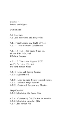
  • 1. Chapter 4 Lenses and Optics CONTENTS 4.1 Overview 4.2 Lens Functions and Properties 4.2.1 Focal Length and Field of View 4.2.1.1 Field-of-View Calculations 4.2.1.1.1 Tables for Scene Sizes vs. FL for 1/4-, 1/3-, and 1/2-Inch Sensors 4.2.1.1.2 Tables for Angular FOV vs. FL for 1/4-, 1/3-, and 1/2-Inch Sensor Sizes 4.2.1.2 Lens and Sensor Formats 4.2.2 Magnification 4.2.2.1 Lens–Camera Sensor Magnification 4.2.2.2 Monitor Magnification 4.2.2.3 Combined Camera and Monitor Magnification 4.2.3 Calculating the Scene Size 4.2.3.1 Converting One Format to Another 4.2.4 Calculating Angular FOV 4.2.5 Lens Finder Kit
  • 2. 4.2.6 Optical Speed: f-number 4.2.7 Depth of Field 4.2.8 Manual and Automatic Iris 4.2.8.1 Manual Iris 4.2.8.2 Automatic-Iris Operation 4.2.9 Auto-Focus Lens 4.2.10 Stabilized Lens 4.3 Fixed Focal Length Lens 4.3.1 Wide-Angle Viewing 4.3.2 Narrow-Angle Telephoto Viewing 4.4 Vari-Focal Lens 4.5 Zoom Lens 4.5.1 Zooming 4.5.2 Lens Operation 4.5.3 Optical Speed 4.5.4 Configurations 4.5.5 Manual or Motorized 4.5.6 Adding a Pan/Tilt Mechanism 4.5.7 Preset Zoom and Focus 4.5.8 Electrical Connections 4.5.9 Initial Lens Focusing 4.5.10 Zoom Pinhole Lens 4.5.11 Zoom Lens–Camera Module 4.5.12 Zoom Lens Checklist 4.6 Pinhole Lens 4.6.1 Generic Pinhole Types 4.6.2 Sprinkler Head Pinhole 4.6.3 Mini-Pinhole
  • 3. 4.7 Special Lenses 4.7.1 Panoramic Lens—360� 4.7.2 Fiber-Optic and Bore Scope Optics 4.7.3 Bi-Focal, Tri-Focal Image Splitting Optics 4.7.4 Right-Angle Lens 4.7.5 Relay Lens 4.8 Comments, Checklist and Questions 4.9 Summary 4.1 OVERVIEW The function of the camera lens is to collect the reflected light from a scene and focus it onto a camera sensor. Choosing the proper lens is very important, since its choice determines the amount of light received by the camera sensor, the FOV on the monitor, and the quality of the image displayed. Understanding the characteristics of the lenses available and following a step-by-step design proce- dure simplifies the task and ensures an optimum design. A CCTV lens functions like the human eye. Both col- lect light reflected from a scene or emitted by a lumi- nous light source and focus the object scene onto some receptor—the retina or the camera sensor. The human eye has a fixed-focal-length (FFL) lens and variable iris 71 72 CCTV Surveillance diaphragm, which compares to an FFL, automatic-iris
  • 4. video lens. The eye has an iris that opens and closes just like an automatic-iris camera lens and automatically adapts to changes in light level. The iris—whether in the eye or in the camera—optimizes the light level reaching the recep- tor, thereby providing the best possible image. The iris in the eye is a muscle-controlled membrane; the automatic iris in a video lens is a motorized device. Of the many different kinds of lenses used in video secu- rity applications the most common is the FFL lens, which is available in wide-angle (90�), medium-angle (40�), and narrow-angle (5�) FOVs. To cover a wide scene and also obtain a close-up (telephoto) view with the same camera, a variable-FOV vari-focal or zoom lens is used. The vari- focal lens is used to “fine tune” the focal length (FL) to a specific FL for the application. To further increase the camera’s FOV a zoom lens mounted on a pan/tilt platform is used. The pinhole lens is used for covert video surveillance applications since it has a small front diameter and can easily be hidden. There are many other specialty lenses, including split-image, fiber optic, right-angle, and auto- matic focus. A relatively new lens—the panoramic 360� lens—is used to obtain a 360� horizontal by up to 90� vertical FOV. This lens must be used with a digital computer and software algorithm to make use of the donut-shaped image it pro- duces on the camera sensor. The software converts the image to a 360� panoramic display. 4.2 LENS FUNCTIONS AND PROPERTIES A lens focuses an image of the scene onto the CCTV cam-
  • 5. era sensor (Figure 4-1). The sensor can be a CCD, CMOS, ICCD, or thermal IR imager. The lens in a human and a camera have some similar- ities: they both collect light and focus it onto a receptor (Figure 4-2). They have one important difference: the human lens has one FFL and the retina is one size, but the camera lens may have many different FLs and the sensor may have different sizes. The unaided human eye is limited to seeing a fixed and constant FOV, whereas the video system can be modified to obtain a range of FOVs. The eye has an automatic-iris diaphragm to optimize the light level reaching the retina. The camera lens has an iris (either manual or automatic) to control the light level reaching the sensor (Figure 4-3). HEIGHT LENS FIELD OF VIEW (FOV) C OR CS VIDEO OUT POWER IN V = VERTICAL HEIGHT H = HORIZONTAL WIDTH D = DIAGONAL
  • 6. H × V = CAMERA SENSOR FOV REFLECTED LIGHT FROM SENSOR NATURAL OR ARTIFICIAL ILLUMINATION SOURCE CAMERA D WIDTH MOUNT SCENE VIEWED BY CAMERA /LENS V H CCD, CMOS, IR SENSOR LENS FIGURE 4-1 CCTV camera/lens, scene, and source illumination Lenses and Optics 73 CAMERA SENSOR FIELD OF VIEW (FOV)
  • 7. SCENE EYE FIELD OF VIEW EYE MAGNIFICATION = 1 EYE LENS FOCAL LENGTH ≈ 17 mm (0.67") EYE RETINA CAMERA SENSOR LENS IRIS 17 mm SENSOR FORMAT 1/2" 1/3" SCENE 1/4" 2/3" FIGURE 4-2 Comparing the human eye to a CCTV lens and camera sensor EYE AUTOMATIC IRIS IRIS ALMOST CLOSED
  • 8. WHEN VIEWING BRIGHT SCENE (SUN) IRIS HALF CLOSED WHEN VIEWING NORMAL SCENE (INDOORS) IRIS WIDE OPEN WHEN VEIWING DARK SCENE (NIGHT TIME) CCTV LENS AUTOMATIC IRIS MOTOR DRIVEN IRIS DRIVE MOTOR/GEAR MOTOR VIDEO SIGNAL METAL LEAVES OPEN AND CLOSE BY MOVING LENS IRIS RING IRIS OPEN HALF CLOSED IRIS NEARLY CLOSED DRIVE FIGURE 4-3 Comparing the human eye and CCTV camera lens
  • 9. iris 74 CCTV Surveillance 4.2.1 Focal Length and Field of View In the human eye, magnification and FOV are set by the lens FL and retina size. When the human eye and the video camera lens and sensor see the same basic picture, they are said to have the same FOV and magnification. In practice, a lens that has an FL and FOV similar to that of the human eye is referred to as a normal lens with a magnification M = 1. The human eye’s focal length—the distance from the center of the lens at the front of the eye to the retina in the back of the eye—is about 17 mm (0.67 inch) (Figure 4-2). Most people see approximately the same FOV and mag- nification (M = 1). Specifically, the video lens and cam- era format corresponding to the M = 1 condition is a 25 mm FL lens on a 1-inch (diagonal) format camera, a 16 mm lens on a 2/3-inch format camera, a 12.5 mm lens on a 1/2-inch camera, an 8 mm lens on a 1/3-inch cam- era, and a 6 mm lens on a 1/4-inch sensor. The 1-inch format designation was derived from the development of the original vidicon television tube, which had a nom- inal tube diameter of 1 inch (25.4 mm) and an actual scanned area (active sensor size) of approximately 16 mm in diameter. Figure 4-4 shows the FOV as seen with a lens having magnifications of 1, 3, and 1/3 respectively. Lenses with much shorter FL used with these sensors are referred to as wide-angle lenses and lenses with much longer FL are referred to as narrow-angle (telephoto)
  • 10. lens. Between these two are medium FL lenses. Telephoto lenses used with video cameras act like a telescope: they magnify the image viewed, narrow the FOV, and effectively bring the object of interest closer to the eye. While there is no device similar to the telescope for the wide-angle example, if there were, the device would broaden the FOV, allowing the eye to see a wider scene than is normal and at the same time causing objects to appear farther away from the eye. One can see this condition when looking through a telescope backwards. This also occurs with the automobile passenger side-view mirror, a concave mirror that causes the scene image to appear farther away, and therefore smaller than it actually is (de-magnified). Just as your own eyes have a specific FOV—the scene you can see—so does the video camera. The camera FOV is determined by the simple geometry shown in Figure 4-5. The scene has a width (W ) and a height (H ) and is at a distance (D) away from the camera lens. Once the scene has been chosen, three factors determine the correct FL lens to use: (1) the size of the scene (H� W ), (2) the distance between the scene and camera lens (D), and (3) the camera image sensor size (1/4-, 1/3-, or 1/2-inch format). NORMAL M = 1 WIDE ANGLE M = 1/3 NARROW ANGLE M = 3
  • 11. MONITOR MONITOR MONITOR FIGURE 4-4 Lens FOV for magnifications of 3, 1, and 1/3 Lenses and Optics 75 DIAGONAL(d ) HORIZONTAL(h) VERTICAL(v ) 11 0.43 8.8 0.35 6.6 0.26 FORMAT 2/3" 1/2" 8 0.31 6.4 0.25 4.8 0.19 6 0.24 4.8 0.19 3.6 0.141/3" inchmm mm mm inchinch 4 0.16 3.2 0.13 2.4 0.11/4" 1" 16 0.63 12.8 0.50 9.6 0.38 1/6" 3 0.12 2.4 0.09 1.8 0.07 LENS VERTICAL HEIGHT
  • 12. D = DISTANCE FROM SCENE TO LENS HORIZONTAL WIDTH CAMERA SENSOR FOV SOLID STATE (CCD) CAMERA D d SENSOR SENSOR GEOMETRY CCTV SCENE TUBE d = DIAGONAL W H VERTICAL = 3 UNITS HIGH HORIZONTAL = 4 UNITS WIDE v
  • 13. h v = VERTICAL h = HORIZONTAL SENSOR SIZE FIGURE 4-5 Camera/lens sensor geometry and formats 4.2.1.1 Field-of-View Calculations There are many tables, graphs, monographs, and linear and circular slide rules for determining the angles and sizes of a scene viewed at varying distances by a video camera with a given sensor format and FL lens. One conve- nient aid in the form of transparent circular scales, called a “Lens Finder Kit,” eliminates the calculations required to choose a video camera lens (Section 4.2.5). Such kits are based on the simple geometry shown in Figure 4-6. Since light travels in straight lines, the action of a lens can be drawn on paper and easily understood. Bear in mind that while commercial video lenses are constructed from multiple lens elements, the single lens shown in Figure 4-6 for the purpose of calculation has the same effective FL as the video lens. By simple geometry, the scene size viewed by the sensor is inversely proportional to the lens FL. Shown in Figure 4-6 is a camera sensor of hor- izontal width (h) and vertical height (v). For a 1/2-inch CCD sensor, this would correspond to h = 6�4 mm and v = 4�8 mm. The lens FL is the distance behind the lens at which the image of a distant object (scene) would focus. The figure shows the projected area of the sensor on the scene at some distance D from the lens. Using the eye analogy, the sensor and lens project a scene W wide × H
  • 14. high (the eye sees a circle as did the original vidicon). As with the human eye, the video lens inverts the image, but the human brain and the electronics re-inverts the image in the camera to provide an upright image. Figure 4-6 shows how to measure or calculate the scene size (W × H ) as detected by a rectangular video sensor format and lens with horizontal and vertical angular FOVs �H and �V , respectively. 4.2.1.1.1 Tables for Scene Sizes vs. FL for 1/4-, 1/3-, and 1/2-Inch Sensors Tables 4-1, 4-2, and 4-3 give scene-size values for the 1/4-, 1/3-, and 1/2-inch sensors, respectively, as a function of the distance from the camera to the object and the lens FL. The tables include scene sizes for most available lenses ranging from 2.1 to 150 mm FL. To find the horizontal FOV �H, we use the geometry of similar triangles: h W = FL D � W = h FL × D (4-1) The horizontal angular FOV �H is then derived as follows: tan
  • 15. �H 2 = h/2 FL �H 2 = tan−1 h 2 FL �H = 2 tan−1 h 2 FL (4-2) 76 CCTV Surveillance θV = VERTICAL ANGLE OF VIEW H SCENE FIXED FOCAL LENGTH LENS CAMERA SENSOR FL
  • 16. D v = SENSOR VERTICAL HEIGHT h = SENSOR HORIZONTAL WIDTH h v W H = SCENE HEIGHT W = SCENE WIDTH CAMERA LOCATION SCENE LOCATION θH = HORIZONTAL ANGLE OF VIEW θH/2 θV/2 FIGURE 4-6 Sensor, lens and scene geometry 1/4 - INCH SENSOR FORMAT LENS GUIDE CAMERA TO SCENE DISTANCE (D) IN FEET WIDTH AND HEIGHT OF AREA (W × H ) IN FEET 5 10 20 30 40 50 75 100 LENS FOCAL LENGTH
  • 17. (mm) ANGULAR FIELD OF VIEW: H × V (DEG.) W × H W × H W × H W × H W × H W × H W × H W × H 2.1 81.2 × 60.9 8.6 × 6.4 17 × 12.9 34 × 26 51 × 39 69 × 51 86 × 64 129 × 96 171 × 129 2.2 78.6 × 59.0 8.2 × 6.1 16.4 × 12.2 33 × 25 49 × 37 65 × 49 82 × 63 123 × 92 164 × 123 2.3 76.1 × 57.1 7.8 × 5.9 15.6 × 11.8 31 × 23 47 × 35 62 × 47 78 × 59 117 × 86 157 × 117 2.6 69.4 × 52 6.9 × 5.2 13.9 × 10.4 28 × 21 42 × 31 55 × 42 6 9 × 52 104 × 78 138 × 104 3.0 61.9 × 46.4 6.0 × 4.5 12 × 9 24 × 18 36 × 27 48 × 36 60 × 45 90 × 68 120 × 90 3.6 53.1 × 39.8 5.0 × 3.8 10 × 7.5 20 × 15 30 × 23 40 × 30 50 × 38 75 × 57 100 × 76 3.8 50.7 × 38.0 4.7 × 3.6 9.5 × 7.1 19 × 14 28 × 21 38 × 28 47 × 36 71 × 54 94 × 72 4.0 48.5 × 36.4 4.5 × 3.4 9 × 6.8 18 × 14 27 × 20 36 × 27 45 × 34 68 × 51 90 × 68 4.3 45.4 × 34.1 4.2 × 3.1 8.4 × 6.3 16.7 × 12.5 25 × 19 33 × 25 42 × 31 63 × 47 84 × 62 6.0 33.4 × 25.0 3 × 2.3 6 × 4.5 12 × 9 18 × 13.5 24 × 18 30 × 23 45 × 35 60 × 46 8.0 25.4 × 19.0 2.3 × 1.7 4.5 × 3.4 9 × 6.8 13.5 × 10.1 18 × 13.5 23 × 17 35 × 26 46 × 34 12.0 17.1 × 12.8 1.5 × 1.1 3 × 2.2 6 × 4.4 9.0 × 6.8 12 × 9 15 × 11 23 × 17 30 × 23 16.0 12.8 × 9.6 1.1 × .8 2.3 × 1.7 4.5 × 3.4 6.8 × 5.1 9 × 6.8 11.2 × 8.4 17 × 13 22 × 17
  • 18. 25.0 8.2 × 6.2 .72 × .54 1.4 × 1.1 2.9 × 2.1 4.3 × 3.2 5.8 × 4.3 7.2 × 5.4 10.8 × 8.1 14.4 × 10.8 NOTE: 1/4 - INCH LENSES ARE DESIGNED FOR 1/4 - INCH SENSOR FORMATS ONLY AND WILLNOT WORK ON 1/3 - INCH OR 1/2 - INCH SENSORS. LENS FOCAL LENGTHS ARE NOMINAL PER MANUFACTURERS’ LITERATURE. ANGULAR FOV AND W × H ARE DERIVED FROM EQUATIONS 4 - 1 TO 4 - 4 AND VERTICAL FOV FROM STANDARD 4:3 MONITOR RATIO: V = 0.75H. Table 4-1 1/4-Inch Sensor FOV and Scene Sizes vs. FL and Camera-to-Scene Distance Lenses and Optics 77 1/3-INCH SENSOR FORMAT LENS GUIDE 5 10 20 30 40 50 75 100 LENS FOCAL LENGTH (mm) ANGULAR FIELD OF VIEW: H × V (DEG.) W × H W × H W × H W × H W × H W × H W × H W × H
  • 19. 92.4 × 69.3 10.4 × 7.8 20.8 × 15.6 41.6 ×3 1.2 63 × 47 83 × 62 104 × 78 156 × 117 208 × 156 85.4 × 64.1 9.2 × 6.9 18.5 × 13.8 36.8 × 27.6 55 × 41 77 × 58 92 × 69 138 × 104 184 × 138 81.2 × 60.9 8.6 × 6.5 17.2 × 13 34.4 × 26 51 × 39 69 × 52 86 × 65 129 × 98 172 × 130 67.4 × 50.5 6.7 × 5.0 13.3 × 10 26.7 × 20 40 × 30 53 × 40 67 × 50 101 × 75 134 × 100 64.6 × 48.4 6.3 × 4.7 12.6 × 9.5 25 × 18.9 37.9 × 28.4 50.5 × 37.9 63 × 47 95 × 71 123 × 92 61.9 × 46.4 6.0 × 4.5 12 × 9 24 × 18 36 × 27 48 × 36 60 × 45 90 × 68 120 × 90 56.1 × 42.1 5.3 × 4.0 10.6 × 8 21.2 × 15.9 31.8 × 23.9 42.4 × 31.8 53 × 40 80 × 60 106 × 80 43.6 × 32.7 4.0 × 3.0 8.0 × 6 16 × 12 24 × 18 32 × 24 40 × 30 60 × 45 80 × 60 33.4 × 25.0 3.0 × 2.3 6 × 4.5 12 × 9 18 × 13.5 24 × 18 30 × 22 .5 45 × 34 60 × 45 26.6 × 20.0 2.0 × 1.5 4.0 × 3.0 8.0 × 6.0 12.0 × 9.0 16 × 12 20 × 15 30 × 23 40 × 30 17.1 × 12.8 1.5 × 1.2 3.0 × 2.3 6.0 × 4.5 9.0 × 6.8 12.0 × 9.0 15.0 × 11.3 23 × 17 30 × 22.5 11.0 × 8.2 .96 × .72 1.9 × 1.4 3.8 × 2.9 5.8 × 4.4 7.7 × 5.8 9.6 × 7.2 14.4 × 10.8 19.2 × 14.4 5.5 × 4.1 .48 × .36 .96 × .72 1.9 × 1.4 2.9 × 2.2 3.8 × 2.8 4.8 × 3.6 7.2 × 5.4 9.6 × 7.2 2.3 2.6 2.8 3.6 3.8
  • 20. 4.0 4.5 6.0 8.0 12.0 16.0 25.0 50.0 75.0 3.7 × 2.8 .32 × .24 .64 × .50 1.3 × .96 1.9 × 1.4 2.6 × 1.9 3.2 × 2.4 4.8 × 3.6 6.4 × 4.8 NOTE: MOST 1/3 - INCH LENSES WILL NOT WORK ON 1/2 - INCH SENSORS BUT ALL WILL WORK ON ALL 1/4 - INCH SENSORS. LENS FOCAL LENGTHS ARE NOMINAL PER MANUFACTURERS’ LITERATURE. ANGULAR FOV AND W × H ARE DERIVED FROM EQUATIONS 4 - 1 TO 4 - 4 AND VERTICAL FOV FROM STANDARD 4:3 MONITOR RATIO: V = 0.75H. CAMERA TO SCENE DISTANCE (D) IN FEET WIDTH AND HEIGHT OF AREA (W × H ) IN FEET Table 4-2 1/3-Inch Sensor FOV and Scene Sizes vs. FL and Camera-to-Scene Distance 1/2-INCH SENSOR FORMAT LENS GUIDE CAMERA TO SCENE DISTANCE (D) IN FEET WIDTH AND HEIGHT OF AREA (W × H ) IN FEET 5 10 20 30 40 50 75 100
  • 21. LENS FOCAL LENGTH (mm) ANGULAR FIELD OF VIEW: H × V (DEG.) W × H W × H W × H W × H W × H W × H W × H W × H 1.4 133 × 100 23 × 17 46 × 34 91 × 69 137 × 103 183 × 137 228 × 171 342 × 257 457 × 348 2.6 101.8 × 76.4 12.3 × 9.2 24.6 × 18 49 × 37 74 × 55 98 × 74 123 × 92 185 × 138 246 × 184 3.5 84.9 × 63.7 9.1 × 6.9 18.2 × 13.8 37 × 28 55 × 41 73 × 55 91 × 69 137 × 104 182 × 138 3.6 83.3 × 62.5 8.9 × 6.7 17.8 × 13.4 36 × 27 53 × 40 71 × 53 89 × 67 134 × 101 178 × 134 3.7 81.7 × 61.3 8.6 × 6.5 17.2 × 13.0 35 × 26 52 × 39 69 × 52 86 × 65 129 × 98 172 × 130 4.0 77.3 × 58.0 8.0 × 6.0 16.0 × 12.0 32 × 24 48 × 36 64 × 24 80 × 60 120 × 90 160 × 120 4.2 74.6 × 56.0 7.6 × 5.7 15.2 × 11.4 30 × 23 48 × 34 61 × 46 76 × 57 114 × 86 156 × 114 4.5 70.8 × 53.1 7.1 × 5.3 14.2 × 10.6 28 × 21 43 × 32 57 × 43 71 × 53 107 × 80 142 × 107 4.8 67.4 × 50.5 6.7 × 5.0 13.4 × 10.0 27 × 20 40 × 30 53 × 40 67 × 50 101 × 75 134 × 100 6.0 56.1 × 42.1 5.3 × 4.0 10.6 × 8.0 21 × 16 32 × 24 43 × 32 53 × 40 80 × 60 106 × 80 7.5 46.2 × 34.7 4.3 × 3.2 8.6 × 6.4 17.1 × 12.8 26 × 19 34 × 26 43 × 32 65 × 48 86 × 64
  • 22. 8.0 43.6 × 32.7 4.0 × 3.0 8.0 × 6.0 16 × 12 24 × 18 32 × 24 40 × 30 60 × 45 80 × 60 12.0 29.9 × 22.4 2.7 × 2.0 5.3 × 4.0 10.7 × 8 16 × 12 21.3 × 16 27 × 20 41 × 30 53 × 40 16.0 22.6 × 17.0 2.0 × 1.5 4.0 × 1.5 8 × 6 12 × 9 16 × 12 20 × 15 30 × 23 40 × 30 25.0 14.6 × 10.9 1.3 × 1.0 2.6 × 2.0 5.1 × 3.8 7.7 × 5.8 10.2 × 7.7 12.8 × 9.6 19 × 14 25.6 × 19.2 50.0 7.3 × 5.5 .64 × .48 1.3 × 1.0 2.6 × 1.9 3.8 × 2.9 5.1 × 3.8 6.4 × 4.8 6.5 × 4.8 12.8 × 9.6 75.0 4.9 × 3.7 .43 × .32 .85 × .64 1.7 × 1.3 2.6 × 1.9 3.4 × 2.6 4.3 × 3.2 3.2 × 2.4 8.6 × 6.4 150.0 2.4 × 1.8 .21 × .16 .43 × .32 .85 × .64 1.3 × .96 1.7 × 1.3 2.1 × 1.6 9.6 × 7.2 4.3 × 3.2 NOTE: ALL 1/2-INCH FORMAT LENSES WILL WORK ON 1/3- AND 1/4 -INCH SENSORS. LENS FOCAL LENGTHS ARE NOMINAL PER MANUFACTURERS’ LITERATURE. ANGULAR FOV AND W × H ARE DERIVED FROM EQUATIONS 4-1 TO 4-4. Table 4-3 1/2-Inch Sensor FOV and Scene Sizes vs. FL and Camera-to-Scene Distance 78 CCTV Surveillance For the vertical FOV, similar triangles give: v H
  • 23. = FL D � H = v FL × D (4-3) The vertical angular FOV �V is then derived from the geometry: tan �v 2 = v/2 FL �v 2 = tan−1 v 2 FL �v = 2 tan−1 v 2 FL (4-4) 4.2.1.1.2 Tables for Angular FOV vs. FL for 1/4-, 1/3-, and 1/2-Inch Sensor Sizes Table 4-4 shows the angular FOV obtainable with 1/4 -, 1/3-, 1/2-, and 2/3-inch sensors with some standard lenses from 1.4 to 150 mm FL. The values of angular FOV in
  • 24. Table 4-4 can be calculated from Equations 4-2 and 4-4. 4.2.1.2 Lens and Sensor Formats Fixed focal length lenses must be used with either the image sensor size (format) for which they were designed or with a smaller sensor size. They cannot be used with larger sensor sizes because unacceptable image distortion and image darkening (vignetting) at the edges of the image occurs. When a lens manufacturer lists a lens for a 1/3-inch sensor format, it can be used on a 1/4-inch sensor but not on a 1/2-inch sensor without producing image vignetting. This problem of incorrect lens choice for a given format size occurs most often when a C or CS mount 1/3-inch format lens is incorrectly used on a 1/2-inch format camera. Since the lens manufacturer does not “over design” the lens, that is, make glass lens element diameters larger than necessary, check the manufacturer’s specifications for proper choice. 4.2.2 Magnification The overall magnification from a specific camera, lens, and monitor depends on three factors: (1) lens FL, (2) camera sensor format, and (3) the monitor size (diag- onal). Video magnification is analogous to film magnifica- tion: the sensor is equivalent to the film negative, and the monitor is equivalent to the photo print. 4.2.2.1 Lens–Camera Sensor Magnification The combination of the lens FL and the camera sensor size defines the magnification Ms at the camera location. For a specific camera, the sensor size is fixed. Therefore, no matter how large the image from the lens is at the sensor, the camera will see only as much of the image as
  • 25. will fit onto the sensor. Lens magnification is measured relative to the eye which is defined as a normal lens. The eye has approximately a 17-mm FL and is equivalent to a 25-mm FL lens on a 1-inch format camera sensor. Therefore, the magnification of a 1-inch (16-mm for- mat) sensor is Ms = Lens focal length (mm) Sensor diagonal (mm) Ms �1 inch� = FL 16 mm (4-5) For 2/3 inch (11-mm format) the magnification is Ms �2/3 inch� = FL 11 mm (4-6) For 1/2 inch (8-mm format) the magnification is Ms �1/2 inch� = FL 8 mm (4-7)
  • 26. For 1/3 inch (5.5-mm format) the magnification is Ms �1/3 inch� = FL 5.5 mm (4-8) For 1/4 inch (4-mm format) the magnification is Ms �1/4 inch� = FL 4 mm (4-9) Example: From Equation 4-7, a 16-mm FL lens on a 1 2 -inch format camera would have a magnification of Ms �1/2 inch� = FL 8 mm = 16 mm 8 mm = 2 4.2.2.2 Monitor Magnification When the camera image is displayed on the CCTV mon- itor, a further magnification of the object scene takes place. The monitor magnification Mm is equivalent to the
  • 27. ratio of the monitor diagonal (dm) to the sensor diagonal (ds) or M�monitor� = Mm = dm ds (4-10) Example: From Equation 4-10, for a 9-inch diagonal mon- itor (dm = 9 inches) and a 1/2 sensor format (ds = 8 mm = 0�315 inch) Mm = 9 0�315 = 28�57 L en ses an d O p tics 79 CAMERA ANGULAR FIELD OF VIEW (FOV) (DEGREES)
  • 28. 1/4 INCH SENSOR 1/3 INCH SENSOR 1/2 INCH SENSOR 2/3 INCH SENSOR LENS FOCAL LENGTH (mm) MAXIMUM IMAGE FORMAT OPTICAL SPEED: f/# LENS MOUNT TYPE HORIZONTAL VERTICAL HORIZONTAL VERTICAL HORIZONTAL VERTICAL HORIZONTAL VERTICAL 1.4 1/2 1.4 CS 101 76 135 101 180 135 2.1 1/4 1.0 CS 91 70 2.2 1/3 1.2 CS 93 69 2.3 1/3 1.4 CS 89 67 113 85 2.6 1/2 1.6 CS 72 54 100 75 128 96 2.8 1/3 1.2 CS 71 53 96 72 3.0 1/4 1.0 CS 65 49 3.5 1/2 1.4 CS, C 59 44 78 59 104 78 3.6 1/2 1/6 CS, C 54 41 72 54 93 71 3.7 1/2 1.6 CS 53 40 71 53 94 70
  • 29. 3.8 1/3 1.4 CS 51 39 68 51 4.0 1/2 1.2 CS 50 37 65 50 89 67 4.2 1/2 1/4 1.6 CS 49 36 64 49 87 65 4.3 1.4 CS 42 35 4.5 1/2 1.4 CS, C 44 34 59 45 79 59 4.8 1/2 1.4 CS, C 39 29 52 39 69 52 96 74 6.0 1/2 1.0 CS 33 25 57 43 57 43 7.5 2/3 2/3 1.4 CS, C 26 20 35 26 46 35 8.0 1.2 CS 25 19 33 25 45 34 58 45 12.0 2/3 1.2 CS, C 28 13 24 28 30 23 39 29 16.0 2/3 1.4 CS, C 13 10 17 13 22 17 31 23 25.0 2/3 1.4 CS, C 8 6 12 9 15 11 20 15 50.0 2/3 1.4 CS, C 4.1 3.1 5.5 4.1 7.3 5.5 10 7.5 75.0 2/3 1.4 CS, C 2.8 2.1 3.7 2.8 4.8 3.6 6.8 5 150.0 1/2 1.6 CS, C 1.4 1.1 1.8 1.4 2.4 1.8 3.3 2.5 NOTE: ALL FOCAL LENGTHS AND ANGULAR FOVs BASED ON MANUFACTURER’S LITERATURE. ALL THE LARGER FORMAT LENSES CAN BE USED ON SMALLER FORMAT SENSORS. LENSES ARE ALSO AVAILABLE HAVING SMALLER FORMATS AND LOWER f/#S THAN THOSE LISTED. Table 4-4 Representative Fixed Lenses Angular FOV vs. Sensor Format and Lens Focal Length
  • 30. 80 CCTV Surveillance 4.2.2.3 Combined Camera and Monitor The combined lens, sensor, and monitor magnification is M = Ms × Mm For the example above and Equation 4-11, the overall mag- nification of the 8-mm FL lens, 1/2-inch format camera, and a 9-inch monitor is M = Ms × Mm = 2 × 28�57 = 57�14 Table 4-5 summarizes the magnification for the entire video system, for a 9- and 17-inch monitor and various lenses and camera formats. It should be noted that increas- ing the magnification by using a larger monitor does not increase the information in the scene; it only increases the size of the displayed picture and permits viewing the monitor from a greater distance. 4.2.3 Calculating the Scene Size Equations 4-1 and 4-3 are used to calculate scene size. For example, calculate the horizontal and vertical scene size as seen by a 1/2-inch CCD sensor using a 12.5 mm FL lens at a distance D = 25 ft. A 1/2-inch sensor is 6.4 mm wide and 4.8 mm high. From Equation 4-1 for horizontal scene width: Scene width = W = h FL × D W = 6.4 mm
  • 31. 12.5 mm × 25 ft = 12.8 ft For vertical scene height, using Equation 4-1: Scene height = H = v FL × D H = 4.8 mm 12.5 mm × 25 ft = 9.6 ft 4.2.3.1 Converting One Format to Another To obtain scene sizes (width and height) for a 1/6-inch sensor, divide all the scene sizes in the 1/3-inch table (Table 4-2) by 2. For a 2/3-inch sensor, multiple all the scene sizes in the 1/3-inch table (Table 4-2) by 2. Understanding Tables 4-1, 4-2, and 4-3 makes it easy to choose the right lens for the required FOV coverage. As an example, choose a lens for viewing all of a building 15 feet high by 20 feet long from a distance of 40 feet with a 1/2-inch format video camera (Figure 4-7). From Table 4-3, a 12-mm FL lens will just do the job. If a 1/4-inch format video camera were used, a lens with an FL of 16 mm would be needed (from Table 4-4, a scene 16.7 feet high by 22.5 feet wide would be viewed). If a 1/3-inch format video camera were used, a lens with an FL of 9 mm would be used (from Table 4-2, a scene
  • 32. 15.2 feet high by 20 feet wide would be viewed). 4.2.4 Calculating Angular FOV Equations 4-2 and 4-4 are used to calculate the horizontal and vertical angular FOV of the lens–camera combination. Table 4-4 shows the angular FOV obtainable with some 1/6 (0.11/2.75) 1/4 (0.15/4.0) 1/3 (0.22/5.5) 1/2 (0.31/8.0) 17 9 72.7 TOTAL MAGNIFICATIONMONITOR SIZE (inch) LENS FOCAL LENGTH mm CAMERA FORMAT (inch/mm) 909.1
  • 35. ALL VALUES BASED ON SENSOR AND MONITOR DIAGONAL EXAMPLE: 1/3-inch FORMAT SENSOR, 3.8 mm FL LENS (0.15 inch), AND 17-inch MONITOR MAGNIFICATION = Ms × Mm, WHERE Ms = LENS FL and, Mm = SENSOR DIAGONAL SENSOR DIAGONAL MONITOR DIAGONAL M = 3.8 mm 17 inch 0.22 inch = 54 5.5 mm × Table 4-5 Monitor Magnification vs. Camera/Monitor Size and Lens Focal Length Lenses and Optics 81 FL FL LENS SENSOR
  • 36. H = SCENE HEIGHT LENS SENSOR W = SCENE WIDTH SIDE VIEW TOP(PLAN) VIEW ANGULAR WIDTH θ H ANGULAR WIDTH θ V H = 22.5 ft W = 30 fth v D = 40 ft D = 40 ft VERTICAL FOV: v/FL = H/D
  • 37. HORIZONTAL FOV: h/FL = W/D SCENE LOCATIONCAMERA LOCATION FIGURE 4-7 Calculating the focal length for viewing a building standard lenses from 2.6 to 75 mm focal length. For the previous example, calculate the horizontal and vertical angular FOVs �H and �V for a 1/2-inch CCD sensor using a 12.5 mm FL lens. The distance need not be supplied, since an angular measure is independent of distance. From Equation 4-2, for horizontal angular FOV: tan �H 2 = h/2 FL = 6�6 mm/2 12�5 mm = 0�264 �H 2 = 14�8� �H = 29�6� From Equation 4-4 for vertical angular FOV: tan �v
  • 38. 2 = v/2 FL = 4�8 mm/2 12�5 mm = 0�192 �v 2 = 10�9� �v = 21�8� Table 4-4 summarizes angular FOV values for some stan- dard lenses from 1.4 to 150 mm FL lenses used on the 1/4-, 1/3-, 1/2- and 2/3-inch sensors. To obtain the angu- lar FOV for sensor sizes, multiply or divide the angles by the ratio of the sensor size. Rule of thumb: for a given lens, angular FOV increases for larger sensor size, decreases for smaller sensor size. 4.2.5 Lens Finder Kit Tables and slide rules for finding lens angular FOVs abound. Over the years many charts and devices have been available to simplify the task of choosing the best lens for a particular security application. Figure 4-8 shows how to quickly determine the correct lens for an application using the Lens Finder Kit (copyright H. Kruegle). There is a separate scale for each of the three camera- sensor sizes: 1/4-, 1/3-, 1/2-inch (the 1/4- and 1/3-inch
  • 39. are shown). The scale for each camera format shows the FL of standard lenses and the corresponding angular hor - izontal and vertical FOVs that the camera will see. To use the kit, the plastic disk is placed on the facility plan drawing and the lens FL giving the desired camera FOV coverage is chosen. For example, a 1/4-inch format camera is to view a horizontal FOV (�H) in a front lobby 30 feet wide at a distance of 30 feet from the camera (Figure 4-9). What FL lens should be used? 82 CCTV Surveillance 2. USING A SCALE DRAWING OF THE FLOOR PLAN (ANY SCALE), PLACE THE CENTER HOLE OF THE DISK AT THE PROPOSED CAMERA LOCATION ON THE FLOOR PLAN. 3. ROTATE THE DISK UNTIL ONE SEGMENT (PIE SECTION) TOTALLY INCLUDES THE HORIZONTAL FIELD OF VIEW REQUIRED. 4. USE THE FOCAL LENGTH LENS DESIGNATED IN THE SEGMENT ON THE DISK. 5. IF THE SCALE DRAWING INCLUDES AN ELEVATION VIEW, FOLLOW STEPS 1 THROUGH 4 AND USE THE VERTICAL ANGLE DESIGNATED IN EACH PIE SEGMENT FOR THE VERTICAL FIELD OF VIEW OF THE LENS. THE LENS FINDER KIT USES THREE TRANSPARENT PROTRACTOR DISKS TO HELP CHOOSE THE BEST LENS WHEN USING THE 1/4-, 1/3- AND 1/2-INCH CCTV CAMERA FORMATS WITH C OR CS MOUNTS. THE DISKS ARE
  • 40. UNIVERSAL AND CAN BE USED 1. SELECT THE DISK TO MATCH THE CAMERA FORMAT: 1/4-, 1/3- OR 1/2-INCH. ON ANY SCALE DRAWING. HOW TO USE: 1/3 INCH FORMAT 1/4 INCH FORMAT NOTE: FOR 2/3- AND 1/2-INCH FORMATS MULTIPLY THE 1/3- AND 1/4-INCH SCALE FOV'S BY 2 8 13 17 24 3 5 54 HORIZ 93 HORIZON TAL 70 48
  • 43. VERT.VE R T. LENS FIN D E R 2.2 m mC C T V © H. KRUEGLE 2007 718 548 488 348 248 17 8 13 8 8 8
  • 45. 728 H O RIZ 648 HOR IZ 3 28 17 2 28 11 948 HORIZON TAL SECU RI TY W O R
  • 47. 2.8 m m C C T V © H. KRUEGLE 2007 FIGURE 4-8 Choosing a lens with the Lens Finder Kit To find the horizontal angular FOV �H, draw the follow- ing lines to scale on the plan: one line to a distance 30 feet from the camera to the center of the scene to be viewed, a line 30 feet long and perpendicular to the first line, and two lines from the camera location to the endpoints of the second 30-foot line. Place the 1/4-inch Lens Finder Kit on the top view (plan) drawing with its center at the camera location and choose the FL closest to the horizon- tal angle required. A 3.6 mm FL lens is closest. This lens will see a horizontal scene width of 30 feet. Likewise for scene height: using the side-view (elevation) drawing, the horizontal scene height is 22.5 feet. 4.2.6 Optical Speed: f-number The optical speed or f-number (f/#) of a lens defines its light-gathering ability. The optical speed of a lens—how much light it collects and transmits to the camera sensor— is defined by a parameter called the f-number (f/#). As the FL of a lens becomes longer, its optical aperture or diameter (d ) must increase proportionally to keep the f-number the same. The f-number is related to the FL and the lens diameter (clear aperture) d by the following
  • 48. equation: f/# = FL d (4-11) For example, an f/2.0 lens transmits four times as much light as an f/4.0 lens. The f-number relationship is analo- gous to water flowing through a pipe. If the pipe diameter is doubled, four times as much water flows through it. Likewise, if the f-number is halved (i.e. if the lens diameter is doubled), four times as much light will be transmitted through the lens. In practice the f-number obtained is worse than this because of various losses caused by imperfect lens transmis - sion, reflection, absorption, and other lens imaging prop- erties. The amount of light (I ) collected and transmitted Lenses and Optics 83 LENS WALL CAMERA SIDE VIEW PLAN TOP VIEW
  • 49. LENS HORIZONTAL FOV θH θV 30 ft 30.6 ft 23.4 ft FORMAT: 1/4 INCH W = 30.6 ft H = 23.4 ft D = 30 ft CAMERA 30 ft 30.6 ft 30 ft FIGURE 4-9 Determining lobby lens horizontal and vertical FOVs through the lens system varies inversely as the square of the lens f-number (K = constant):
  • 50. I = K �f /#�2 Long-FL lenses are larger (and costlier) than short-FL lenses, due to the cost of the larger optical elements. It can be seen from Equation 4-11 that the larger the d is made, the smaller the f/# is, i.e. more light gets to the camera sensor. The more light the lens can collect and transfer to the camera image sensor the better the pic- ture quality: a larger lens permits the camera to operate at lower light levels. This light-gathering ability depends on the size (diameter) of the optics: the larger the optics the more the light that can be collected. Most human eyes have the same size lens (approxi- mately 7 mm lens diameter). In video systems, however, the lens size (the diameter of the front lens) varies over a wide range. The optical speed of video lenses varies sig- nificantly: it varies as the square of the diameter of the lens. This means a lens having a diameter twice that of another will pass four times as much light through it. Like a garden hose, when the diameter is doubled, the flow is quadrupled (Figure 4-10). The more the light passing through a lens and reaching the video sensor the better the contrast and picture image quality. Lenses with low f-numbers, such as f/1.4 or f/1.6, pass more light than lenses with high f-numbers. The lens optical speed is related to the FL and diameter by the equation f/# = focal length/diameter. So the larger the FL given the same lens diameter, the “slower” the lens (less light reaches the sensor). A slow lens might have an f-number of f/4 or f/8.
  • 51. Most lenses have an iris ring usually marked with num- bers such as 1.4, 2.0, 2.8, 4.0, 5.6, 8.0, 11, 16, 22, C, repre- senting optical speed, f-numbers, or f-stops. The difference between each of the iris settings represents a difference of a factor of 2 in the light transmitted by the lens. Opening the lens from, say, f/2.0 to f/1.4 doubles the light trans- mitted. Only half the light is transmitted when the iris opening is reduced from, say, f/5.6 to f/8. Changing the iris setting two f-numbers changes the light by a factor of 4 (or 1/4), and so on. Covering the f/# range from f/1.4 to f/22 spans a light-attenuation range of 256 to 1. The C designation on the lens indicates when the lens iris is closed and no light is transmitted. In general, faster lenses collect more light energy from the scene, are larger, and are more expensive. In calculating the overall cost of a video camera lens system, a more expensive, fast lens often overrides the higher cost incurred if a more sensitive camera is needed or additional lighting must be installed. 84 CCTV Surveillance WATER LENS D = 2 D = DIAMETER LIGHTFLOW TRANSMISSIONANALOGY LENS WATER FLOW: 4X
  • 52. LIGHT TRANSMISSION: 4X f / # = OPTICAL SPEED f/2 f/4 HOSE D = 1 FIGURE 4-10 Light transmission through a lens 4.2.7 Depth of Field The depth of field in an optical system is the distance that an object in the scene can be moved toward or away from the lens and still be in good focus. In other words, it is the range of distance toward and away from the cam- era lens in which objects in the scene remain in focus. Ideally this range would be very large: say, from a few feet from the lens to hundreds of feet, so that essentially all objects of interest in the scene would be in sharp focus. In practice this is not achieved because the depth of field is: (1) inversely proportional to the focal length, and (2) directly proportional to the f-number. Medium to long FFL lenses operating at low f-numbers—say, f/1.2 to f/4.0—do not focus sharp images over their useful range of from 2 or 3 feet to hundreds of feet. Long focal length lenses—say, 50–300 mm—have a short depth of field and can produce sharp images only over short distances and must be refocused manually or automati- cally (auto-focus) when viewing objects at different scene distances.
  • 53. When these lenses are used with their iris closed down to, say, f/8 to f/16, the depth of field increases significantly and objects are in sharp focus at almost all distances in the scene. Short focal length lenses (2�7–5 mm) have a long depth of field. They can produce sharp images from a few feet to 50–100 feet even when operating at low f-numbers 4.2.8 Manual and Automatic Iris The lens iris is either manually or automatically adjusted to optimize the light level reaching the sensor (Figure 4-3). The manual iris is adjusted with a ring on the lens. The auto-iris uses an internal mechanism and motor (or gal- vanometer) to adjust the iris. 4.2.8.1 Manual Iris The manual-iris video lens has movable metal “leaves” forming the iris. The amount of light entering the cam- era is determined by rotating an external iris ring, which opens and closes these internal leaves. Figure 4-11 shows a manual iris FFL lens and the change in light transmitted through it at different settings of the iris. Solid-state CCD and CMOS camera sensors can oper- ate over wide light-level changes with manual-iris lenses but require automatic-iris lenses when used over their full light-level range, that is, from bright sunlight to low- level nighttime lighting. Some solid-state cameras use electronic shuttering (Section 5.5.3) and do not require an automatic-iris lens. 4.2.8.2 Automatic-Iris Operation Automatic-iris lenses have an electro-optical mechanism
  • 54. whereby the amount of light passing through the lens is adjusted depending on the amount of light available from the scene and the sensitivity of the camera. The camera video signal provides the information used for adjusting the light passing through the lens. The sys- tem works something like this: if a scene is too bright for the camera, the video signal will be strong (large in ampli - tude). This large signal will activate a motor or galvanome- ter that causes the lens iris circular opening to become smaller in diameter, thereby reducing the amount of light reaching the camera. When the amount of light reach- ing the camera produces a predetermined signal level, the motor or galvanometer in the lens stops and main- tains that light level through the lens. Likewise if too little light reaches the camera, the video camera signal level is small and the automatic-iris motor or galvanometer opens up the iris diaphragm, allowing more light to reach the camera. In both the high and the low light level con- ditions the automatic-iris mechanism produces the best Lenses and Optics 85 MANUAL IRIS LENS 1 1/2 1/4 1/8 1/16 1/32 1/64 1/128 1/256 1/512 0 C = LENS IRIS FULLY CLOSED LIGHT TRANSMISSION 1 1.4 2.0 2.8 4.0 5.6 8.0 11.0 22.0 C16.0
  • 55. f/# MARKINGS f/# NOTE: REFERENCE LIGHT LEVEL = 1 AT f/1.4 EACH INCREASE OR DECREASE IN f/# REPRESENTS ONE f STOP FOCUSING RING FIGURE 4-11 Lens f/# vs. light transmission contrast picture. Automatic-iris lenses are available to com- pensate the full range of light, from bright sunlight to darkness. There are two types of automatic-iris lenses: direct drive and video drive. The two methods used to control these two lens types are: DC motor (or galvanometer) drive or video signal drive. With the DC drive method the camera has all the electronics and directly drives the DC motor in the lens with a positive or a negative signal to open and close the iris depending on the light level. With the video method the camera video signal drives the electron- ics in the lens which then drives the DC motor (or gal- vanometer) in the lens. Figure 4-12 shows some common automatic-iris lenses. A feature available on some automatic-iris lenses is called average-peak response weighting which permits opti- mizing the picture still further based on the variation in lighting conditions within the scene. Scenes with high-contrast objects (bright headlight, etc.) are bet- ter compensated for by setting the automatic-iris con-
  • 56. trol to peak, so that the lens ignores (compensates for) the bright spots and highlights in the scene (see Section 5.5.5). Low-contrast scenes are better compen- sated by setting the control to average. Figure 4-13 illus- trates some actual scenes obtained when these adjust- ments are made. Automatic-iris lenses should only be used with cameras having a fixed video gain in their system. Automatic-iris lenses are more expensive than their man- ual counterparts, with the price ratio varying by about two or three to one. 4.2.9 Auto-Focus Lens Auto-focus lenses were originally developed for the con- sumer camcorder market and are now available to the security market (similar to the solid-state sensor evolu- tion). There are two types of auto-focus techniques in use. One auto-focus system uses a ranging (distance measur- ing) means to automatically focus the scene image onto the sensor. A second type analyzes the video signal in by means of DSP electronics, and forces the lens to focus on the target in the scene. The function of both these types of systems is to keep objects of interest in focus on the camera sensor even though they move toward or away from the lens. These lenses are particularly useful when a person (or vehicle) enters a camera FOV and moves toward or away from the camera. The auto-focus lens changes focus from the surrounding scene and focuses on the moving object (automatically) to keep the mov- ing object in focus. Various types of automatic-focusing techniques are used, including: (1) active IR ranging, (2) ultrasonic wave, (3) solid-state triangulation, and (4) video signal DSP.
  • 57. 86 CCTV Surveillance (A) DC MOTOR IN LENS, ELECTRONICS IN CAMERA (B) VIDEO ELECTRONICS IN CAMERA FIGURE 4-12 Automatic-iris fixed focal length (FFL) lenses (A) HIGH CONTRAST SCENES OPTIMIZED USING MEDIUM RESPONSE WEIGHTING (C) LOW CONTRAST SCENES OPTIMIZED USING AVERAGE RESPONSE WEIGHTING (B) NORMAL CONTRAST SCENES OPTIMIZED USING PEAK RESPONSE WEIGHTING FIGURE 4-13 Automatic-iris enhanced video scenes 4.2.10 Stabilized Lens A stabilized lens is used when it is necessary to remove unwanted motion of the lens and camera with respect to the scene being viewed. Applications for stabilized lenses include handheld cameras, cameras on moving ground vehicles, airborne platforms, ships, and cameras on towers and buildings. Stabilized lenses can remove significant image vibration (blurring) in pan/tilt mounted cameras that are buffeted by wind or the motion caused by the mov- ing vehicle. The stabilized lens system has movable optical components and/or active electronics that compensate for (move in the opposite direction to) the relative motion between the camera and the scene. An extreme example
  • 58. Lenses and Optics 87 of a stabilized video camera system is the video image from a helicopter. The motion compensation results in a steady, vibration free scene image on the monitor. Figure 4-14 shows a stabilized security lens and samples of pictures taken with and without the stabilization on. 4.3 FIXED FOCAL LENGTH LENS Video lenses come in many varieties, from the simple, small, and inexpensive mini pinhole and “bottle cap” lenses to complex, large, expensive, motorized, automatic- iris zoom lenses. Each camera application requires a spe- cific scene to be viewed and a specific intelligence to be extracted from the scene if it is to be useful in a secu- rity application. Monitoring a small front lobby or room to see if a person is present may require only a simple lens. It is difficult, however, to determine the activity of a person 100–200 feet away in a large showroom. Appre- hending a thief or thwarting a terrorist may require a high-quality, long FL zoom lens and a high resolution camera mounted on a pan/tilt platform. Covert cameras using pinhole lenses are often used to uncover internal theft, shoplifting, or other inappropriate or criminal activ- ity. They can be concealed in inconspicuous locations, installed quickly, and moved on short notice. The follow - ing sections describe common and special lens types used in video surveillance applications. The majority of lenses used in video applications are FFL lenses. Most of these lenses are available with a man- ual focusing ring to adjust the amount of light passing through the lens and reaching the image sensor. The very short FL lenses (less than 6 mm) often have no manual
  • 59. iris. FFL lenses are the workhorses of the industry. Their attributes include low cost, ease of operation, and long life. Most FFL lenses are optically fast and range in speed from f/1.2 to f/1.8, providing sufficient light for most cameras to produce an excellent quality picture. The manual-iris lenses are suitable for medium light-level when used with most solid-state cameras. Most FFL lenses have a mount which in the industry for attaching the lens to the camera is called a C or CS mount (Figure 4-15). The C mount has been a standard in the CCTV industry for many years while the CS mount was introduced in the mid-1990s to match the trend toward smaller camera sen- sor formats and their correspondingly smaller lens require- ments. The C and CS mount has a 1 inch 32 threads per inch thread. Most security surveillance cameras are now manufactured with a CS mount and supplied with a 5 mm thick spacer adapter ring which allows a C mount lens to be attached to the CS mount camera. The C mount focuses the scene image 0.69 inches (17.5 mm) behind the lens onto the camera sensor. The CS mount focuses the scene image 0.394 inches (10 mm) behind the lens onto the sensor. Commonly used CS mount FLs vary from 2.5 mm (A) LENS (D) STABILIZED IMAGE (C) UNSTABILIZED IMAGE (B) LENS FIGURE 4-14 Stabilized lenses and results
  • 60. 88 CCTV Surveillance 1"-32 TPI CCD/CMOS SENSOR 17.526 mm (0.69") 12.5 mm (0.492") BACK FOCAL DISTANCE IMAGE PLANE MECHANICAL BACK FOCAL DISTANCE CCD/CMOS SENSOR 1"-32 TPI C MOUNT CS MOUNT MECHANICAL LENS GEOMETRY FLANGE BACK FOCAL LENGTH (F,f ) SCENE
  • 61. TPI = THREADS PER INCH FIGURE 4-15 C and CS mount lens mounting dimensions (wide-angle) to 200 mm (telephoto). The C mount is also used for long FL lenses having large physical dimensions. Large optics are designed to be used with almost any sen- sor format size from 1/4 to 1 inch. Lenses with FLs longer than approximately 300 mm are large and expensive. As the FL becomes longer the diameter of the lens increases and costs escalate accordingly. Most FFL lenses are avail - able in a motorized or automatic-iris version. These are necessary when they are used with LLL ICCD cameras in daytime and nighttime applications where light level must be controlled via an automatic iris or neutral density filters depending on the scene illumination. With the widespread use of smaller cameras and lenses a new set of lens–camera mounts developed. They were not given any special name but are referred to as 11 mm, 12 mm (the most common), and 13 mm mounts. The dimensions refer to the diameter of the thread on the lens and the camera mount. Figure 4-16 shows these lens mounts. Note that the threads are not all the same (the 13 mm mount is different from the 11 mm and 12 mm). 4.3.1 Wide-Angle Viewing While the human eye has peripheral vision and can detect the presence and movement of objects over a wide angle (160�), the eye sees a focused image in only about the central 10� of its FOV. No video camera has this unique eye characteristic, but a video system’s FOV can be increased (or decreased) by replacing the lens with one having a
  • 62. shorter (or longer) FL. The eye cannot change its FOV without the use of external optics. Choosing different FL lenses brings trade-offs: reducing the FL increases the FOV but reduces the magnification, thereby making objects in the scene smaller and less dis- cernible (i.e. decreasing resolution). Increasing the FL has the opposite effect. To increase the FOV of a CCTV camera, a short-FL lens is used. The FOV obtained with wide-angle lenses can be calculated from Equations 4-1, 4-2, 4-3, and 4-4, or by using Table 4-4, or the Lens Finder Kit. For example, substituting an 8 mm FL, wide-angle lens for a 16 mm lens on any camera doubles the FOV. The magnification is reduced to one-half, and the camera sees “twice as much but half as well.” By substituting a 4 mm FL lens for the 16 mm lens, the FOV quadruples. We see sixteen times as much scene area but one-fourth as well. A 2.8 mm FL lens is an example of a wide-angle lens; it has an 82� horizontal by 67� vertical FOV on a 1/3-inch sensor. A super wide FOV lens for a 1/2-inch sensor is the 3.5 mm FL lens, with an FOV approximately 90� hor- izontal by 75� vertical. Using a wide-angle lens reduces THREAD: 13 mm DIA. × 1.0 mm PITCH SENSOR MOST COMMON MOUNT: 12 mm DIA. × 0.5 mm PITCH THREAD: 12 mm DIA. × 0.5 mm PITCH THREAD: 10 mm DIA. x 0.5 mm PITCH BACK FOCAL
  • 63. LENGTH RANGES FROM 3 mm TO 9 mm FIGURE 4-16 Mini-lens mounting dimensions Lenses and Optics 89 FL = 4.0 mm FL = 25 mm FL = 75 mm NARROW ANGLE (TELEPHOTO) NOTE: ANGULAR FOV SHOWN FOR 1/3-, 1/2-, AND 2/3- INCH FORMAT SENSORS 1/2" 1/3" TELEPHOTO (SHADED) NORMAL FOR 1" SENSOR FL = 8 MM NORMAL FOR 1/3" SENSOR WIDE ANGLE 1/4" FIGURE 4-17 Wide-angle, normal, and narrow-angle (Telephoto) FFL lenses vs. format
  • 64. the resolution or ability to discern objects in a scene. Figure 4-17 shows a comparison of the FOV seen on 1/4-, 1/3-, and 1/2-inch format cameras with wide-angle, nor- mal, and telephoto lenses. 4.3.2 Narrow-Angle Telephoto Viewing When the lens FL increases above the standard M = 1 magnification condition the FOV decreases and the mag- nification increases. Such a lens is called a medium- or narrow-angle (telephoto) lens. The lens magnification is determined by Equations 4-5, 4-10, 4-8, and 4-9 for the reference (1 inch) and three commonly used sensor sizes (see also Table 4-4 and the Lens Finder Kit). Outdoor security applications often require viewing scenes hundreds and sometimes thousands of feet away from the camera. To detect and/or identify objects, persons, or activity at these ranges requires very long- FL lenses. Long-FL lenses between 150 and 1200 mm are usually used outdoors to view these parking lots or other remote areas. These large lenses require very stable mounts and rugged pan-tilt drives to obtain good picture quality. The lenses must be large (3–8 inches in diameter) to collect enough light from the distant scene and have usable f-numbers (f/2.5 to f/8) for the video camera to produce a good picture on the monitor. Fixed focal length lenses having FLs from 2.6 mm up to several hundred millimeters are refractive- or glass-type. Above approximately 300 mm FL, refractive glass lenses become too large and expensive, and reflective mirror optics or mirror and glass optics are used to achieve opti - cally fast (low f-number) lenses with lower weight and size. These long FL telephoto lenses, called “Cassegrain”
  • 65. or “catadioptric lenses,” cost hundreds to thousands of dollars. Figure 4-18 shows a schematic of these lenses, a 700 mm f/8.0 and a 300 mm f/5.6 lens used for long- range outdoor surveillance applications. 4.4 VARI-FOCAL LENS The vari-focal lens is a variable focal length lens developed to be used in place of an FFL lens (Figure 4-19). In general it is smaller and costs much less than a zoom lens. The advantage of the vari-focal lens over an FFL lens is that its focal length and FOV can be changed manually 90 CCTV Surveillance SCENE WINDOW L = CORRECTING LENSES M2 M1 SENSOR FOCAL PLANE M1 = PRIMARY MIRROR M2 = SECONDARY MIRROR
  • 66. LIGHT FROM DISTANT L FIGURE 4-18 Long-range, long-focal length catadioptric lenses SENSOR VARI-FOCAL LENS FOCAL LENGTH 3–8 mm 3 mm FOV 8 mm FOV FIGURE 4-19 Vari-focal lens configuration by rotating the barrel on the lens. This feature makes it convenient to adjust the lens FOV to a precise angle while installed on the camera. The lenses were developed to be used in place of FFL lenses to “fine tune” the FL for a particular application. Having the ability to adjust the FL “on the job” makes it easier for the installer and at the same time permits the customer to select the exact FOV necessary to observe the desired scene area. One minor inconvenience of the vari-focal lens is that it must be refocused each time the FL is changed. Typical vari - focal lenses are available with focal lengths of: 3–8 mm, 5–12 mm, 8–50 mm, 10–120 mm (Table 4-6). With just these few lenses focal lengths of from 1.8–120 mm and
  • 67. 144–1�6� FOVs can be covered continuously (i.e.—any focal length in the range). The vari-focal lenses are a sub- set and simplified version of zoom lenses but they are not a suitable replacement for the zoom lens in a variable FOV pan/tilt application. Lenses and Optics 91 HORIZONTAL ANGULAR FOV (DEG.) 1/4 INCH 1/3 INCH 1/2 INCH 2/3 INCH FOCAL LENGTH (mm) ZOOM RATIO FORMAT (INCH) OPTICAL SPEED f/# WIDE TELE WIDE TELE WIDE TELE WIDE TELE 1.4–3.1 2.2:1 1/3 1.4 121 69.5 185 94.5 1.6–3.4 2.1:1 1/3 1.4 135 101 180 84.3 1.8–3.6 2:1 1/3 1.6 144 79.0 2.2–6 2.7:1 1/4 1.2 90.0 34.7 2.7–12 4.4:1 1/3 1.2 75 56 97.4 23.8 2.8–12 4.3:1 1/3 1.4 73 54.7 97.4 24.1 3.0–8 2.7:1 1/3 1.4 67.0 26.0 89.5 34.0 3.0–8 2.7:1 1/3 1.0 67.0 27 91 36
  • 68. 3.5–8 2.3:1 1/3 1.4 58.7 26.5 79.8 35.4 3.6–18 5:1 1/2 1.8 54.4 11.5 72.3 54.3 95.9 20.0 4.5–12.5 2.8:1 1/2 1.2 45.9 34.4 61.2 45.9 81.6 30.0 5.0–50 10:1 1/3 1.3 39.0 4.2 52 5.6 5.5–82.5 15:1 1/3 1.8 35.3 2.5 47.1 3.3 6–12 2:1 1/2 1.4 31.6 16.8 42.1 22.4 56.1 29.9 6–15 2.5:1 1/2 1.4 33.1 14.4 44.1 19.2 59.1 25.7 6–60 10:1 1/3 1.6 32.7 3.5 43.6 4.7 7–70 10:1 1/2 1.8 29.0 3.0 38.2 4.0 50.0 5.1 8–16 2:1 1/2 1.6 24.5 12.6 33.6 16.8 43.5 22.4 59.8 30.8 8–80 10:1 1/2 1.6 25 26 33.0 3.5 42.9 4.6 10–30 3:1 1/2 1.4 20 7.1 27 9.4 36 12.5 10–40 4:1 1/3 1.4 20.6 5.3 27.5 7.0 20–100 5:1 1/3 1.6 10.2 2.1 13.6 2.8 NOTE: HORIZONTAL ANGULAR FOV FROM MANUFACTURERS’ SPECIFICATIONS Table 4-6 Representative Vari-Focal Lenses—Focal Length, Vari-Focal Zoom Ratio vs. Sensor Format, Horizontal FOV 4.5 ZOOM LENS Zoom and vari-focal lenses are variable FL lenses. The lens components in these assemblies are moved to change their relative physical positions, thereby varying the FL and angle of view through a specified range of magnifications. Prior to the invention of zoom optics, quick conversion to different FLs was achieved by mounting three or four different FFL lenses on a turret with a common lens mount in front of the CCTV camera sensor and rotating each lens into position, one at a time, in front of the sensor. The lenses usually had wide, medium, and short FLs to achieve
  • 69. different angular coverage. This turret lens was obviously not a variable-FL lens and had limited use. 4.5.1 Zooming Zooming is a lens feature that permits seeing detailed close-up views (high magnification) of a subject (scene target) or a broad (low magnification), overall view of an area. Zoom lenses allow a smooth, continuous change in the angular FOV. The angle of view can be made narrower or wider depending on the zoom setting. As a result, a scene can be made to appear close-up (high magnification) or far away (low magnification), giving the impression of camera movement toward or away from the scene, even though the camera remains in a fixed posi- tion. Figure 4-20 shows the continuously variable nature of the zoom lens and how the FOV of the video camera can be changed without replacing the lens. To implement zooming, several elements in the lens are physically moved to vary the FL and thereby vary the angular FOV and magnification. Tables 4-1, 4-2, 4-3, and 4-4, and the Lens Finder Kit can be used to determine the FOV for any zoom lens. By adjusting the zoom ring setting, one can view narrow-, medium-, or wide-angle scenes. This allows a person to view a scene with a wide-angle perspec- tive and then close in on one portion of the scene that is of specific interest. The zoom lens can be made significantly more useful and providing the camera a still wider FOV by mounting it on a pan/tilt platform controlled from a remote console. The pan/tilt positioning and the zoom lens variable FOV from wide to narrow angle and anywhere in between provide a large dynamic FOV capability. 4.5.2 Lens Operation
  • 70. The zoom lens is a cleverly designed assembly of lens elements that can be moved to change the FL from a wide angle to a narrow angle (telephoto) while the image on the sensor remains in focus (Figure 4-21). This is a significant difference from the vari-focal lens 92 CCTV Surveillance CAMERAWIDE-ANGLE LIMIT NARROW-ANGLE TELEPHOTO LIMIT HORIZONTAL FIELD OF VIEW VERTICAL FIELD OF VIEW ZOOM LENS FIGURE 4-20 Zoom lens variable focal length function FOCUS RING ZOOM RING IRIS RING
  • 71. FRONT OBJECTIVE GROUP MOVABLE ZOOM GROUP REAR STATIONARY GROUP IRIS FOCUSING RELAY CAMERA SENSOR FIGURE 4-21 Zoom lens configuration Lenses and Optics 93 which must be re-focused each time its FL is changed (Section 4.4). A zoom FL lens combines at least three moveable groups of elements:
  • 72. 1. The front focusing objective group that can be adjusted over a limited distance with an external focus ring to initially fine-focus the image onto the camera sensor. 2. A movable zoom group located between the front and the rear group that moves appreciably (front to back) using a separate external zoom ring. The zoom group also contains corrective elements to optimize the image over the full zoom range. Other lenses are also moved a small amount to automatically adjust and keep the image on the sensor in sharp focus, thereby eliminating subsequent external adjustment of the front focusing group. 3. The rear stationary relay group at the camera end of the zoom lens that determines the final image size when it is focused on the camera sensor. Each lens group normally consists of several elements. When the zoom group is positioned correctly, it sees the image produced by the objective group and creates a new image from it. The rear relay group picks up the image from the zoom group and relays it to the cam- era sensor. In a well-designed zoom lens a scene in focus at the wide-angle (short-FL) setting remains in focus at the narrow-angle (telephoto) setting and everywhere in between. 4.5.3 Optical Speed Since the FL of a zoom lens is variable and its entrance aperture is fixed, its f-number is not fixed (see Equa- tion 4-11). For this reason, zoom lens manufacturers often list the f-number for the zoom lens at the wide and nar- row FLs, with the f-number at the wide-angle setting being
  • 73. faster (more light throughput, lower f-number) than at the telephoto setting. For example, a 11–110 mm zoom lens may be listed as f/1.8 when set at 11 mm FL and f/4 when set at 110 mm FL. The f-number for any other FL in between the two settings lies in between these two values. 4.5.4 Configurations Many manufacturers produce a large variety of manual and motorized zoom lenses suitable for a wide variety of applications. Figure 4-22 shows two very different zoom lenses used for surveillance applications. The manual zoom lens shown has a 8�5–51 mm FL (6:1 zoom ratio) and has an optical speed of f/1.6. The long range lens shown has a large zoom ratio of 21:1. This lens has an FL range of 30–750 mm and speed of f/4.6. Figure 4-23 shows the FOVs obtained from a 11–110 mm FL zoom lens on a 1/2-inch sensor camera at three zoom FL settings. Table 4-7 is a representative list of manual and motor- ized zoom lenses, from a small, lightweight, inexpensive 8–48 mm FL zoom lens to a large, expensive, 13.5–600 mm zoom lens used in high-risk security areas by industry, mil- itary, and government agencies. Zoom lenses are available with magnification ratios from 6:1 to 50:1. Many have special features, including remotely controlled preset zoom and focus positions, auto-focus and stabilization. 4.5.5 Manual or Motorized
  • 74. The FL of a zoom lens is changed by moving an exter- nal zoom ring either manually or with an electric motor. When the zoom lens iris, focus, or zoom setting must be adjusted remotely, a motorized lens with a remote con- troller is used. The operator can control and change these (A) MANUAL (B) MOTORIZED FIGURE 4-22 Manual and motorized zoom lenses 94 CCTV Surveillance SCENE ZOOM LENS 11–110 mm NOTE: THE LENS HAS A CIRCULAR FOV BUT THE SENSOR 4:3 ASPECT RATIO FOV IS SHOWN 11 mm FL 24 mm FL 110 mm FLWIDE: 46° MEDIUM: 24° NARROW: 5° 46° 24° 5°
  • 75. 2 /3-INCH SENSOR FORMAT HORIZONTAL ZOOM ANGLES FIGURE 4-23 Zoom lens FOV at different focal length settings HORIZONTAL ANGULAR FOV (DEG.) 1/4 INCH 1/3 INCH 1/2 INCH 2/3 INCH FOCAL LENGTH (mm) ZOOM RATIO FORMAT (INCH) OPTICAL SPEED: f/# WIDE T ELE WIDE TELE WIDE TELE WIDE TELE 4.5–54 12:1 1/4 1.1 43.5 3.7 4.6–28 6:1 1/4 1.0 41.6 7.5 5.5–77 14:1 1/3 1.4 36.2 2.6 47.1 3.5 5.5–187 34:1 1/3 1.8 35.0 1.1 46.6 1.5 5.7–34.2 6:1 1/3 1.0 34.5 6.1 46 8.1 5.8–121.8 21:1 1/3 1.6 33.8 1.7 45 2.3
  • 76. 6–72 12:1 1/3 1.5 33.4 2.8 43.6 3.8 6–90 15:1 1/3 1.2 33.0 2.3 43.8 3.1 7.5–105 14:1 1/2 1.4 27.0 2.0 35.5 2.6 46.2 3.5 8–48 6:1 1/2 1.0 24.9 4.4 33.0 5.9 43.2 7.7 8–96 12:1 1/2 2.0 25.3 2.2 33.4 2.8 43.5 3.7 8–160 20:1 1/2 2.0 25.1 1.3 33.4 1.7 43.6 2.3 9–180 20:1 1/3 1.2 22.6 1.2 30.3 1.5 10.5–105 10:1 2/3 1.4 18.6 2.0 24.8 2.6 33.0 3.5 45.5 4.8 10–140 14:1 2/3 1.9 19.9 1.5 26.4 2.0 35.0 2.7 47.5 3.6 10–200 20:1 1/2 2.5 20.3 1.1 27.0 1.4 35.5 1.8 10–300 30:1 1/2 1.5 20.0 0.7 26.6 0.9 35.5 1.25 12.5–75 6:1 2/3 1.6 16.1 2.8 21.4 3.7 28.4 4.9 38.8 6.7 12–120 10:1 1/2 1.8 16.6 1.7 22.1 2.3 29.4 3.1 12–240 20:1 1/2 1.6 17.2 0.9 23.0 1.2 30.8 1.6 16–160 10:1 1 1.8 16.8 1.8 22.4 2.4 30.8 3.2 44.9 4.6 10–500 50:1 1/2 4.0 13.7 0.3 18.2 0.4 35.5 0.7 NOTE: NOMINAL HORIZONTAL ANGULAR FOV FROM MANUFACTURERS’ SPECIFICATION Table 4-7 Representative Motorized Zoom Lenses—Focal Length, Zoom Ratio vs. Sensor Formats, Horizontal FOV Lenses and Optics 95 settings remotely using toggle switch controls on the con- sole or automatically through preprogrammed software. The motor and gear mechanisms effecting these changes are mounted within the zoom lens. Manual zoom lenses are not very practical for surveillance since an operator is
  • 77. not located at the camera location and cannot manually adjust the zoom lens. 4.5.6 Adding a Pan/Tilt Mechanism A zoom lens and camera pointed in a fixed direction pro- vides limited viewing. When the zoom lens is viewing wide angle it sees a large FOV, but when it is zoomed to a nar- row angle it will zoom in and magnify only in one pointing direction—straight ahead of the camera. This is of limited use unless it is pointing at a area of importance such as an entrance door, entry/exit gate, receptionist, i.e. one single location. To fully utilize a zoom lens it is mounted on a pan-tilt mechanism so that the lens can be pointed in almost any direction (Figure 4-24). By varying the lens zoom control and moving the pan/tilt platform, a wide dynamic FOV is achieved. The pan-tilt and lens controller remotely adjusts pan, tilt, zoom, and focus. The lens usually has an automatic iris, but in some cases the operator can choose a manual- or automatic-iris setting on the lens or the controller. In surveillance applications, one shortcoming of a pan-tilt mounted zoom lens is the existence of “dead zone” viewing areas since the lens cannot point and see in all directions at once. 4.5.7 Preset Zoom and Focus In a computer-controlled surveillance system a motorized zoom lens with electronic preset functions is used. In this mode of operation as a preset zoom lens, the zoom and focus ring positions are monitored electrically and memo-
  • 78. rized by the computer during system setup. These settings (presets) are then automatically repeated on command by the computer software at a later time. In this surveillance application, this feature allows the computer to point the camera–lens combination according to a set of predeter- mined conditions and adjust pointing and the zoom lens FL and focus: i.e. (1) azimuth and elevation angle, (2) focused at a specific distance and (3) iris set to a spe- cific f-number opening. When a camera needs to turn to another preset set of conditions in response to an alarm sensor or other input, the preset feature eliminates the need for human response and significantly reduces the time to acquire a new target. SCENE PAN/ TILT POINTING RANGE ZOOM LENS NARROW FOV ZOOM LENS WIDE FOV CAMERA LENS PAN/ TILT PLATFORM RANGE POINTING PAN/ TILT
  • 79. ZOOM LENS CAN BE POINTED ANYWHERE WITHIN PAN/ TILT POINTING RANGE FIGURE 4-24 Dynamic FOV of pan/tilt-mounted zoom lens 96 CCTV Surveillance 4.5.8 Electrical Connections The motorized zoom lens contains electronics, motors, and clutches to control the movement of the zoom, focus, and iris adjustment rings, and end-of-travel limit switches to protect the gear mechanism. Since the electrical connections have not been standard- ized among manufacturers, the manufacturer’s lens wiring diagram must be consulted for proper wiring. Figure 4-25 shows a typical wiring schematic for zoom, focus, and iris mechanisms. The zoom, focus, and iris motors are con- trolled with positive and negative DC voltages from the lens controller, using the polarity specified by the manu- facturer. 4.5.9 Initial Lens Focusing To achieve the performance characteristics designed into a zoom lens, the lens must be properly focused onto the camera sensor during the initial installation. Since the lens operates over a wide range of focal lengths it must be tested and checked to ensure that it is in focus at the wide-angle and telephoto settings. To perform a crit- ical focusing of the zoom lens the aperture (iris) must
  • 80. be wide open (set to the lowest f-number) for all back- focus adjustments of the camera sensor. This provides the conditions for a minimum depth of field, and the con- ditions to perform the most critical focusing. Therefore, adjustments must be performed in subdued lighting, or with optical filters in front of the lens, to reduce the light and allow the lens iris to open fully to get minimum depth of field. The following steps should be followed to focus the lens: 1. With the camera operating, view an object at least 50 feet away. 2. Make sure the lens iris is wide open so that focusing is most critical. 3. Set the lens focus control to the extreme far position. 4. Adjust the lens zoom control to the extreme wide-angle position (shortest FL). 5. Adjust the camera sensor position adjustment control to obtain the best focus on the monitor. 6. Move the lens zoom to the extreme telephoto (longest FL) setting. 7. Adjust the lens focus control (on the controller) for the best picture. 8. Re-check the focus at the wide-angle (position of short- est FL). CAMERA
  • 82. ZOOM + 12 V TELE *** COMMON REQUIRES POSITIVE AND NEGATIVE VOLTAGE REMOTE CONTROL ** * DEPENDS ON MANUFACTURER: RANGES FROM 8 TO 12 VDC TYPICAL ** REQUIRES POSITIVE AND NEGATIVE VOLTAGE: ±6 VDC MAX TYPICAL *** DEPENDING ON THE CONTROLLER THIS MAY BE ±6 OR ±12 VDC MAX FIGURE 4-25 Motorized zoom lens electrical configuration Lenses and Optics 97 4.5.10 Zoom Pinhole Lens Pinhole lenses with a small front lens element are com- mon place in covert video surveillance applications. Zoom pinhole lenses while not as common as FFL pinhole lenses are available in straight and right-angle configuration. One lens has an FL range of 4−12 mm and an optical speed of f/4.0. 4.5.11 Zoom Lens–Camera Module The requirement for a compact zoom lens and camera combination has been satisfied with the zoom lens–camera
  • 83. module. This module evolved out of a requirement for a lightweight, low-inertia camera lens for use in high-speed pan-tilt dome installations in casinos and retail stores. The camera–lens module has a mechanical cube configuration (Figure 4-26) so that it can easily be incorporated into small pan-tilt dome housings and be pointed in any direc- tion at high speeds. The module assembly includes the following compo- nents and features: (1) rugged, compact mechanical structure suitable for high-speed pan-tilt platforms, (2) large optical zoom ratio, typically 20:1, and (3) sensitive 1/4- or 1/3-inch solid-state color camera with excellent sensitivity and resolution. Options include: (1) automatic- focus capability, (2) image stabilization, and (3) elec- tronic zoom. 4.5.12 Zoom Lens Checklist The following should be considered when applying a zoom lens: FIGURE 4-26 Compact zoom lens–camera cube • What FOV is required? See Tables 4-1, 4-2, 4-3, 4-4, and the Lens Finder Kit. • Can a zoom lens cover the FOV or must a pan-tilt plat- form be used? • Is the scene lighting constant or widely varying? Is a manual or automatic iris required? • What is the camera format: 1/4-, 1/3-, 1/2-inch? • What is the camera lens mount type: C, or CS? • Is auto-focus or stabilization needed?
  • 84. • Is electronic zoom required to extend the FL range? Zoom lenses on pan-tilt platforms significantly increase the viewing capability of a video system by providing a large range of FLs all in one lens. The increased complexity and precision required in the manufacture of zoom lenses makes them cost three to ten times as much as an FFL lens. 4.6 PINHOLE LENS A pinhole lens is a special security lens with a relatively small front diameter so that it can be hidden in a wall, ceiling, or some object. Covert pinhole lens–camera assem- blies have been installed in emergency lights, exit signs, ceiling-mounted lights, table lamps, and even disguised as a building sprinkler head fixture. Any object that can house the camera and pinhole lens and can disguise or hide the front lens element is a candidate for a covert installation. In practice the front lens is considerably larger than a pinhole, usually 0�06−0�38 inch in diameter, but nevertheless it can be successfully hidden from view. Vari- ations of the pinhole lens include straight or right-angle, manual or automatic iris, narrow-taper or stubby-front shape (Figure 4-27). The lenses shown are for use with C or CS mount cameras. Whether to use the straight or right-angle pinhole lens depends on the application. A detailed description and review of covert camera and pin- hole lenses are presented in Chapter 18. 4.6.1 Generic Pinhole Types A feature that distinguishes two generic pinhole lens designs from each other is the shape and size of the front taper (Figure 4-28). The slow tapering design permits eas- ier installation than the fast taper and also has a faster optical speed, since the larger front lens collects more
  • 85. light. The optical speed (f-number) of the pinhole lens is important for the successful implementation of a covert camera system. The lower the f-number of the lens, the more the light reaching the camera and the better the video picture. An f/2.2 lens transmits 2.5 times more light than an f/3.5. The best theoretical f-number is equal to 98 CCTV Surveillance (A) MANUAL IRIS FAST TAPER (B) AUTOMATIC IRIS FAST TAPER (C) MANUAL IRIS SLOW TAPER (D) RIGHT ANGLE MANUAL IRIS SLOW TAPER (E) RIGHT ANGLE AUTOMATIC IRIS SLOW TAPER FIGURE 4-27 Straight and right-angle pinhole lenses the FL divided by the entrance lens diameter (d ). From Equation 4-11: f/# = FL d For a pinhole lens, the light getting through the lens to the camera sensor is limited primarily by the diameter of the front lens or the mechanical opening through which it views. For this reason, the larger the lens entrance diam- eter, the more light gets through to the image sensor,
  • 86. resulting in a better picture quality, if all other conditions remain the same. 4.6.2 Sprinkler Head Pinhole There are many types of covert lenses available for the security industry: pinhole, mini, fiber optic, camera-lenses covertly concealed in objects. The sprinkler head cam- era is a unique pinhole lens hidden in a ceiling sprin- kler fixture which makes it extremely difficult for an observer standing at floor level to detect or identify. This unique device provides an extremely useful covert surveil - lance system. Figure 4-29 shows the configuration and two versions of the sprinkler head lens, the straight and right-angle. This pinhole lens and camera combination is con- cealed in and above a ceiling using a modified sprinkler head to view the room below the ceiling. For investiga- tive purposes, fixed pinhole lenses pointing in one spe- cific direction are usually suitable. To look in different directions there is a panning sprinkler head version. An integral camera-lens-sprinkler head design is shown in Section 18.3.5. 4.6.3 Mini-Pinhole Another generic family of covert lenses is the mini-lens group (Figure 4-30). They are available in conventional on- axis and special off-axis versions. Their front mechanical shape can be flat or cone shaped. These lenses are very small, some with a cone-shaped front, typically less than 1/2 inch diameter by 1/2 inch long and mount directly onto a small video camera. The front lens in these mini-lenses ranges from 1/16 inch to
  • 87. 3/8 inch diameter. The cone-shaped mini-lens is easier to install in many applications. These mini-lenses are opti- cally fast having speeds of f/1.4 to f/1.8 and can be used in places unsuitable for larger pinhole lenses. An f/1.4 mini - pinhole lens transmits five times more light than an f/3.5 pinhole lens. Mini-pinhole lenses are available in FLs from 2.1 to 11 mm and when combined with a good camera Lenses and Optics 99 SLOW-TAPER BARREL FAST-TAPER BARREL 30° 55° SMALL DIAMETER LARGE DIAMETER CEILING TILE FIGURE 4-28 Short vs. long tapered pinhole lenses CAMERA SPRINKLER HEAD MOVEABLE MIRROR CEILING TILE
  • 88. LENS/CAMERA FIELD OF VIEW MANUAL IRIS CEILING TILE SPRINKLER HEAD CAMERA STRAIGHT RIGHT-ANGLE RIGHT-ANGLE PINHOLE SPRINKLER LENS STRAIGHT PINHOLE SPRINKLER LENS FIGURE 4-29 Sprinkler head pinhole assembly installation 100 CCTV Surveillance FIGURE 4-30 Mini-pinhole lenses
  • 89. 11 mm 8 mm IN C MOUNT 8 mm IN WATEC OFFSET MOUNT 11 mm IN WATEC OFFSET MOUNT 2.1 mm 3.8 mm 3.7 mm PINHOLE 8 mm result in the fastest covert cameras available. A useful varia- tion of the standard mini-lens is the off-axis mini-lens. This lens is mounted offset from the camera axis, which causes the camera to look off to one side, up, or down, depend- ing on the offset direction chosen. Chapter 18 describes pinhole and mini-lenses in detail. 4.7 SPECIAL LENSES There are several special video security lenses and lens func- tions that deserve consideration. These include: (1) a new panoramic 360� lens, (2) fiber-optic and bore scope, (3) split-image, (4) right-angle, (5) relay, (6) automatic-focus, (7) stabilized, and (8) long-range. The new panoramic lens must be integral with a camera and used with computer hardware and software (Section 5.10). The other special
  • 90. lenses are used in applications when standard FFL, vari - focal or zoom lenses are not suitable. The auto-focus and stabilizing functions are used to enhance the performance of zoom lenses, vari-focal, fixed focus lenses, etc. 4.7.1 Panoramic Lens—360� There has always been a need to see “all around” i.e. an entire room or other location, seeing 360� with one panoramic camera and lens. To date, a 360� FOV cam- era system has only been achieved with multiple cameras and lenses and combining the images on a split-screen monitor. This lens is usually mounted in the ceiling of a room or on a tower. Panoramic lenses have been avail - able for many years but have only recently been combined with powerful digital electronics, sophisticated mathemat- ical transformations and compression algorithms to take advantage of their capabilities. The availability of high res - olution solid-state cameras has made it possible to map a 360� by 90� hemispherical FOV into a standard rectan- gular monitor format with good resolution. Figure 4-31 shows two panoramic lens having a 360� horizontal FOV and a 90� vertical FOV. In operation the lens collects light from the 360� panoramic scene and focuses it onto the camera sensor as a donut-shaped image (Figure 4-32). The electronics and mathematical algorithm convert this donut-shaped panoramic image into the rectangular (horizontal and ver- tical) format for normal monitor viewing. (Section 2.6.5 describes the panoramic camera in detail.) 4.7.2 Fiber-Optic and Bore Scope Optics
  • 91. Coherent fiber-optic bundle lenses can sometimes solve difficult video security applications. Not to be confused with the single or multiple strands of fiber commonly used to transmit the video signal over long distances, the coher - ent fiber-optic lens has many thousands of individual glass fibers positioned adjacent to each other. These thousands of fibers transmit a coherent image from an objective lens, over a distance of several inches to several feet, where the image is then transferred again by means of a relay lens to the camera sensor. A high-resolution 450 TV lines coher- ent fiber bundle consists of several hundred thousand glass fibers that transfer a focused image from one end of the fiber bundle to the other. Coherent optics means that each point in the image on the front end of the fiber bundle corresponds to a point at the rear end. Since the picture quality obtained with fiber-optic lenses is not as good as that obtained with all glass lenses, such lenses should only Lenses and Optics 101 LENS SEES FULL HEMISPHERE: 360° × 180° 360° 90° HORIZ. FOV VERT. FOV 360° LENS
  • 92. RAW DONUT IMAGE FROM 360° LENS FIGURE 4-31 Panoramic 360� lens camera module A B CD A B CD A B CD LENS SEES FULL HEMISPHERE: 360° × 180° IMAGE FORMED ON SENSOR DONUT RING IMAGE REPRESENTING HEMISPHERE FOV: 360 H × 180 V ALGORITHM TO CONVERT DONUT SHAPED PANORAMIC IMAGE TO NORMAL LINEAR X,Y LENS FEATURES: SEES ENTIRE AREA INCLUDING DIRECTLY BELOW INFINITE DEPTH OF FIELD: NO FOCUSING REQUIRED NO MOVING PARTS FOR P/ T/ Z–ALL ELECTRONIC
  • 93. FLUSH CEILING (OR WALL) MOUNTING PC SOFTWARE / HARDWARE 0° 90° 0° 360° NORMAL 360° FORMAT IMAGE SENSOR DISPLAY NORMAL 360° 90° HORIZ. FOV VERT. FOV 360° PANORAMIC CAMERA /SENSOR • • • • FIGURE 4-32 Panoramic lens layout and description
  • 94. 102 CCTV Surveillance (A) OBJECTIVE LENS: 8 mm OR 11 mm FL FIBER TYPE: RIGID CONDUIT RELAY LENS: M = 1:1 MOUNT: C OR CS (B) OBJECTIVE LENS: ANY C OR CS MOUNT FIBER TYPE: FLEXIBLE BUNDLE RELAY LENS: M = 1:1 MOUNT: C OR CS FIGURE 4-33 Rigid and flexible fiber optic lenses be used when no other lens–camera system will solve the problem. Fiber-optic lenses are expensive and available in rigid or flexible configurations (Figure 4-33). In the complete fiber-optic lens, the fiber bundle is to be preceded by an objective lens, FFL or other, which focuses the scene onto the front end of the bundle and followed by a relay lens that focuses the image at the rear end of the bundle onto the sensor (Figure 4-34). Fiber-optic lenses are used in security applications for viewing through thick walls (or ceilings), or any installa- tion where the camera must be a few inches to several feet away from the front lens, for example the camera G G G
  • 95. G COHERENT 6 to 12 INCHES LONG FIBER OPTIC BUNDLE OBJECTIVE LENSRELAY LENS IMAGE ON SENSOR CAMERA SENSOR SCENE SCENE IMAGE FIBER OPTIC OUTPUT SCENE FIGURE 4-34 Fiber-optic lens configuration Lenses and Optics 103 on an accessible side of a wall and the front of the lens
  • 96. on the inaccessible scene side. In this situation the lens is a foot away from the camera sensor. Chapter 18 shows how coherent fiber-optic lenses are used in covert security applications. The bore scope lens is another class of viewing optics for video cameras (Figure 4-35). This lens has a rigid tube of 6−30 inches long and a diameter of 0�04–0�5 inches. The two generic designs, single rod lens and multiple small lenses, transmit the image from the front objective lens to the rear lens and onto a camera sensor. The single rod lens uses a unique graded index (GRIN) glass rod, to refocus the image along its length. Bore scope lenses can only transmit a small amount of light because of the small rod or lens diameters. This results in high f-numbers, typically f/11 to f/30. The slow speed limits the bore scope application to well-illuminated environments and sensitive cameras. The image quality of the bore scope lens is better than that of the fiber - optic lens, since it uses all glass lenses. Figure 4-35 shows the diagram of a GRIN bore scope lens 0.125 inches in diameter and 12 inches long, and an all-lens bore scope with a diameter of 0.187 inches and a length of 18 inches. The latter has a mirror at the tip to allow viewing at right- angles to the lens axis. 4.7.3 Bi-Focal, Tri-Focal Image Splitting Optics A lens for imaging two independent scenes onto a single video camera is called an image-splitting or bi-focal lens. The split-image lens has two female C or CS lens ports for two objective lenses. The lens views two different scenes with two separate lenses, and combines the scenes onto one camera sensor (Figure 4-36).
  • 97. Each of the two objective lenses can have the same or different FLs and will correspondingly produce the same or different magnifications. The split-image lens accom- plishes this with only one camera. Depending on the orien- tation of the bifocal lens system on the camera, the image is split either vertically or horizontally. Any fixed-focus, pinhole, vari-focal, zoom, or other lens that mechanically fits onto the C or CS mount can be used. The adjustable mirror mounted on the side lens allows the camera to look in almost any direction. This external mirror can point at the same scene as the front lens. In this case, if the front lens is a wide-angle lens (4 mm FL) and the side lens is a narrow-angle lens (50 mm FL), a bifocal lens system results: one camera views a wide-field and narrow- field simultaneously (Figure 4-36). Note that the horizontal scene FOV covered by each lens is one-half of the total lens FOV. For example, with the 4 mm and 50 mm FL lenses on a 1/3-inch camera and a vertical split (as shown), the CAMERA RELAY LENSES WORKING LENGTH CAMERA RIGHT ANGLE STRAIGHT FRONT LOOKING RELAY LENS RELAY
  • 98. LENS GRADIENT INDEX LENS SINGLE GRADED INDEX (GRIN) LENS MULTIPLE DISCRETE LENSES OBJECTIVE SECTION SECTION OBJECTIVE SENSOR VIEWING HEAD SENSOR VIEWING HEAD FIGURE 4-35 Bore scope lens system 104 CCTV Surveillance HORIZONTAL SPLIT VERTICAL SPLIT M M
  • 99. M = ADJUSTABLE MIRROR NARROW FOV WIDE FOV SCENE B SCENE A A B A B SCENE A SCENE B MOVEABLE MIRROR FIGURE 4-36 Bi-focal split-image optics 4 mm lens displays a 30 × 45 feet scene, and the 50-mm lens displays a 2�4 × 3�6 feet scene at a distance of 50 feet. The horizontal FOV of each lens has been reduced by one- half of what each lens would see if the lens were mounted directly onto the camera (60 × 45 feet for the 4 mm lens and 4.8 × 3.6 feet for the 50 mm lens). By rotating the split- image lens 90� about the camera optical axis a horizontal split is obtained. In this case the vertical FOV is halved. It should be noted that the bifocal lens inverts the picture on the monitor, a condition that is simply corrected by inverting the camera.
  • 100. A three-way or tri-split optical image-splitting lens views three scenes (Figure 4-37). The tri-split lens provides the ability to view three different scenes with the same or different magnifications with one camera. Each scene occupies one-third of the monitor screen. Adjustable optics on the lens permit changing the pointing elevation angle of the three front lenses so that they can look close-in for short hallway applications and all the way out (near hor- izontal) for long hallways. Like the bi-split lens, this lens inverts the monitor image, which is corrected by inverting the camera. Both the bi-split and the tri-split lenses work on 1/4-, 1/3-, or 1/2-inch camera formats. The image splitting is accomplished without electronic splitters and is useful when only one camera is installed but two or three scenes need to be monitored. 4.7.4 Right-Angle Lens The right-angle lens permits mounting a camera parallel to a wall or ceiling while the lens views a scene at 90� to the camera axis and wall or ceiling (Figure 4-38). When space is limited behind a wall, a ceiling, in an automatic teller machine (ATM) or an elevator cab, the right-angle lens is a solution. The right-angle optical sys- tem permits use of wide-angle lenses (2.6 mm, 110� FOV) looking at right angles to the camera axis. This cannot be accomplished by using a mirror and a wide-angle lens directly on the camera since the entire scene will not be reflected by the mirror to the lens on the camera. The edges of the scene will not appear on the monitor because of picture vignetting (Figure 4-39). The right-angle adapter permits the use of any FL lens
  • 101. that will mechanically fit into its C or CS mount and works with 1/4-, 1/3-, or 1/2-inch camera formats. Lenses and Optics 105 SCENE 1 SCENE 2 SCENE 3 FRONT LENS SECTION MOVES UP AND DOWN TO CHANGE VERTICAL POINTING ANGLE 1 MONITOR DISPLAY CAMERA LENS 1 LENS 2 LENS 3 2 3 FIGURE 4-37 Tri-split lens views three scenes NARROW OR WIDE ANGLE
  • 102. C OR CS MOUNT ANY C OR CS MOUNT LENS CAMERA RIGHT ANGLE RELAY LENS MONITOR DISPLAY FULL SCENE FIGURE 4-38 Right angle lens 106 CCTV Surveillance WIDE-ANGLE LENS CAMERA SENSOR THIS PART OF SCENE IS BLOCKED BY LENS THIS PART OF SCENE IS NOT REFLECTED OFF MIRROR
  • 103. FRONT SURFACE MIRROR FIGURE 4-39 Picture vignetting from wide-angle lens and mirror 4.7.5 Relay Lens The relay lens is used to transfer a scene image focused by any standard lens, fiber-optic or bore scope lens onto the camera sensor (Figure 4-40). The relay lens must always be used with some other objective lens and does not produce an image in and of itself. When used at the fiber bundle output end, a fiber-optic lens re-images the scene onto the sensor. When incorporated into split-image or right-angle optics, RELAY LENS OBJECTIVE LENS CAMERA FOCUSED SCENE IMAGE IRIS FOCUSED SCENE IMAGE SCENE
  • 104. AUTO IRIS RELAY LENS WITH C MOUNT LENS FIGURE 4-40 Relay lens adapter Lenses and Optics 107 it re-images the “split” scene or right-angle scene onto the sensor. The relay lens can be used with a standard FFL, pinhole, zoom, or other lens as a lens extender with unit magnification (M = 1), for the purpose of optically “moving” the sensor out in front of the camera. 4.8 COMMENTS, CHECKLIST AND QUESTIONS • A standard objective lens inverts the picture image, and the video camera electronics re-invert the picture so that it is displayed right-side-up on the monitor. • The 25 mm FL lens is considered the standard or ref- erence lens for the 1-inch (actually 16 mm diagonal) format sensor. This lens–camera combination is defined to have a magnification of M = 1 and is similar to the normal FOV of the human eye. The standard lens for a 2/3-inch format sensor is 16 mm; for a 1/2-inch sensor is 12.5 mm; for a 1/3-inch sensor is 8 mm; and for a 1/4- inch sensor is 6 mm. All these combinations produce a magnification M = 1. They all have the same angular FOV and therefore view the same size scene. • A short-FL lens has a wide FOV (Table 4-3; 4.8 mm, 1/2- inch sensor sees a 13.4 feet wide × 10.0 feet high scene at 10 feet).
  • 105. • A long-FL lens has a narrow FOV (Table 4-3; 75 mm, 1/2-inch sensor sees a 4.3 feet wide × 3.2 feet high scene at 50 feet). • To determine what FOV is required for an application, consult Tables 4-1, 4-2, 4-3, 4-4 and the Lens Finder Kit. • If the exact FOV desired cannot be obtained with an FFL, use a vari-focal lens. • Does the application require a manual or motorized zoom lens, a pan-tilt mount? • Is the scene lighting constant or widely varying? Is a manual or automatic iris required? • What is the camera format (1/4-, 1/3-, 1/2-inch)? • What type of camera lens mount: C, CS, mini 11 mm, 12 mm, 13 mm, bayonet, or other? 4.9 SUMMARY The task of choosing the right lens for a security applica- tion is an important aspect in designing a video security system. The large variety of focal lengths and lens types make the proper lens choice a challenging one. The lens tables and Lens Finder Kit provide convenient tools for choosing the optimum FL lens to be used and the result- ing angular FOV obtained with the chosen sensor size. The common FFL lenses used in most video systems have FLs in the range of 2.8–75 mm. Super wide-angle applications may use a 2.1 mm FL. Super telephoto appli -
  • 106. cations may use FLs from 100 to 300 mm. Most in the range of 2.8–75 mm are available with a manual or auto- matic iris. Vari-focal lenses are often chosen when the exact FL desired cannot be obtained with the FFL. The vari-focal lens can “fine tune” the focal length exactly to obtain the angular FOV required. Vari-focal lenses are available in manual and auto-iris configurations. Vari-focal lenses must be re-focused when their FL is changed. Zoom lenses are used when the camera and lens must be scanned over a large scene area and the magnifica- tion of the scene must be changed. This is accomplished by mounting the camera-lens on a pan-tilt platform capa- ble of remotely panning and tilting the camera-lens assem- bly and zooming the zoom lens. Zoom lenses are available with FLs from 8 to 200 mm with zoom ratios from 6 to 50 to 1. The zoom lens is available with a manual or auto- matic iris. When the video security application requires that the camera and lens be hidden, covert pinhole lenses and mini-pinhole lenses are used. The pinhole lenses are mounted to cameras having a C or CS mounts. The mini- pinhole lenses are mounted directly onto a small sin- gle board camera (with or without housing) and hidden behind walls or ceilings or mounted into common objects: PIR motion sensor, clock, emergency light, sprinkler head, etc.). Chapter 18 describes covert video lenses and systems in more detail. Special lenses like the bi- and tri-split, fiber-optic or bore scope lenses are only used when other simpler techniques can not be used.
  • 107. The newly implemented 360� panoramic lens is used with a computer system and can view a 360� horizontal FOV and up to a 90� vertical FOV. This lens has taken an important place in digital video surveillance systems. The computer transforms the complex donut-shaped image into a useful rectangular image on the monitor.