Petroleum refining (3 of 3)
•Download as PPTX, PDF•
11 likes•2,367 views

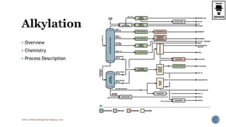
The document discusses the alkylation process. It begins with an overview of the chemistry and components involved. It then describes the typical process which involves reacting olefins like propylene and butylene with iso-paraffins like isobutane in the presence of an acid catalyst to produce a high-octane gasoline blendstock called alkylate. The document concludes by noting that alkylation is an important process for meeting gasoline regulations given alkylate's low emissions profile.

Recommended
More Related Content
What's hot
What's hot (20)
Similar to Petroleum refining (3 of 3)
Similar to Petroleum refining (3 of 3) (20)
More from Chemical Engineering Guy
More from Chemical Engineering Guy (20)
Recently uploaded
Recently uploaded (20)
Petroleum refining (3 of 3)
- 1. Overview Chemistry Process Description www.ChemicalEngineeringGuy.com
- 2. Overview Chemistry Process Description www.ChemicalEngineeringGuy.com
- 3. www.ChemicalEngineeringGuy.com Fuel Gas Sulfur C3 LPG C4 LPG Kerosene Premium Gasoline Regular Gasoline Auto Diesel Heating Oil Haring Diesel Heavy Fuel Oil Bunker Oil
- 4. In an alkylation process: Olefins + iso-paraffins alkylate product (C7-C8 naphtha) The basic purpose of alkylation is to enhance the octane number of the feed stock. Typical Components: propylene (C3) butylenes (C4) + isobutane amylene (C5 ) Butylene is the most widely used olefin because of the high quality of the alkylate produced. Isobutane is typically the iso-paraffin used www.ChemicalEngineeringGuy.com Enjoying the course!? Access all Content: video lecture + PDF + Tasks + Q&A Section HERE Check out more Courses here
- 5. Typical Scheme: Gas Plant separates Olefins: For Polimerization For Alkylation In refining, the alkylation unit produces a high-quality gasoline blendstock by combining two LPG-range molecules to form one gasoline-range molecule. This involves reacting isobutane with some type of light olefin, typically either propylene or butylene coming from the FCC. www.ChemicalEngineeringGuy.com
- 6. Alkylate is a key component in reformulated gasoline. In US and Europe about alkylate is about 11-12% and 6%in the gasoline pool respectively. Alkylation processes are becoming important due to growing demand for high octane gasoline Legislative regulations requirements Low RVP Low Sulphur Low toxics. Alkylate is an ideal blend stock to meet these requirement. www.ChemicalEngineeringGuy.com
- 7. In 1930s, catalyst used was aluminium chloride (AlCl3) catalyst New catalyst was replaced by HF + sulfuric acid. The process of HF alkylation produces high octane blend stock from: iso-parraffin (mainly iso butane) olefin (propylene, butylene and amylenes) NOTE: Replacing high risk toxic liquid acids (HF and H2SO4) Vs. solid acid catalysts is challenging goal iso- parraffin alkylation technology. www.ChemicalEngineeringGuy.com Enjoying the course!? Access all Content: video lecture + PDF + Tasks + Q&A Section HERE Check out more Courses here
- 8. Note that alkylation of amylenes obtained from C5 fraction of FCC can be another route to increase the availability of alkylate. Alkylation of C5 cut from FCC can significantly reduce RVP of finished gasoline pool. C5 alkylate, Amylene alkylation has two fold advantage: It increase the volume of alkylate available Decreases Reid vapor pressure & Olefinic content of gasoline blend stocks www.ChemicalEngineeringGuy.com
- 9. Some of the other side reaction is the formation of paraffin This typically will boil above and below the desired product. Impurities in the feed acid and normal operating practices all can contribute to additional side reactions. Key factors: Maintaining proper composition of reaction mixture: isobutene olefins + the HF acid Maintaining the proper reaction environment: Correct contacting controlled temperature Freedom from surges. Making a proper separation of the reactor effluent into its various components www.ChemicalEngineeringGuy.com
- 10. Alkylate is considered a premium gasoline This mainly because of: Low sulfur content - Alkylate has no sulfur Low aromatics content - Alkylate contains no aromatics Low vapor pressure - Alkylate has a low vapor pressure C4 alkylate has an RVP of 2.6 psi C3 alkyate has an RVP of 3.8 psi C5 alkylate has an RVP of 4.0 psi High octane - Alkylate has medium to high octane depending on the type C4 alkylate has a RON of 94-98 (MON of 92-94) C3 alkylate has a RON of 89-92 (MON of 88-90) C5 alkylate has a RON of 90-92 (MON of 88-93) www.ChemicalEngineeringGuy.com
- 11. To avoid olefin polymerization, high isobutane to olefin ratios are used. Typical isobutene to olefin ratios are 5:1 to 15:1 Acid catalysts are used. Sulphuric acid (H2SO4) www.ChemicalEngineeringGuy.com
- 12. Reaction operating temperature 10 - 20°C using H2SO4 Reaction temperature 4.4 bar for H2SO4 When H2SO4 is used refrigeration is used. Reaction increases C7-C8 HC Propane and Butanes must be recycled Removal of gases are required www.ChemicalEngineeringGuy.com
- 13. Alkylation reactor: The reactor is arranged as a series of CSTRs with acid fed in the first CSTR and feed supplied to different CSTRs. This arrangement is for maximizing the conversion. In the alkylation reactor it is important to note that the olefin is the limiting reactant and isoparaffin is the excess reactant. www.ChemicalEngineeringGuy.com
- 14. The reactor has two phases: olefin + isoparaffin mixture which will be lighter the alkylate stream which will be heavier Alkylate will be appearing as a bottom fraction if allowed to settle. www.ChemicalEngineeringGuy.com Enjoying the course!? Access all Content: video lecture + PDF + Tasks + Q&A Section HERE Check out more Courses here
- 15. Phase separator: the acid enters the organic rich stream and will be subjected to phase separation by settling. Olefin/isoparaffin mixture will be also separated by gravity settling. Thus the phase separator produces three streams: (a) olefin + isoparaffin rich phase (b) acid rich stream (c) alkylate rich stream. www.ChemicalEngineeringGuy.com
- 16. Olefin + Paraffin processing: The olefin + paraffin stream is first subjected to compression followed by cooling. When this stream is subjected to throttling and phase separation: olefin + paraffin rich stream will be generated. The propane rich stream from this stream is generated as another stream in the phase separator. www.ChemicalEngineeringGuy.com
- 17. Propane defractionator: The propane rich stream after cooling is fed to a fractionator: propane is separated from the olefin + isoparaffin mixture. The O-IP mix is sent back to mix with the olefin feed. www.ChemicalEngineeringGuy.com
- 18. Caustic wash for alkylate rich stream: The caustic wash operation ensures to completely eliminate acid concentration from the alkylate. The feed mixture (olefin + C4 compounds) are first subjected to caustic wash. During caustic wash, sulphur compounds are removed and spent caustic is recycled back to the caustic wash. Fresh caustic solution is added to take care of the loss. www.ChemicalEngineeringGuy.com
- 19. Alkylate fractionation separation The alkylate is fed to a distillation column that is supplied with: isobutane feed alkylate feeds This produces: isobutane as a top product alkylate + butane mixture as a bottom product. www.ChemicalEngineeringGuy.com Enjoying the course!? Access all Content: video lecture + PDF + Tasks + Q&A Section HERE Check out more Courses here
- 20. Debutanizer: The debutanizer separates butane and alkylate using the concept of distillation. www.ChemicalEngineeringGuy.com
- 22. To avoid olefin polymerization, high isobutane to olefin ratios are used. Typical isobutene to olefin ratios are 5:1 to 15:1 Acid catalysts are used. HF are used. Reaction operating temperature 25 – 40°C using HF Reaction temperature 7.8 bar for HF When HF is used, refrigeration is not used. www.ChemicalEngineeringGuy.com
- 23. The process is similar to the sulphuric acid plant. However, additional safety issues make the process complex. The feed is first subjected to drying followed by pre-cooling. After pre-cooling the reaction mixture is fed to a reactor. www.ChemicalEngineeringGuy.com Enjoying the course!? Access all Content: video lecture + PDF + Tasks + Q&A Section HERE Check out more Courses here
- 24. Unlike CSTRs in series here impeller reactors are used. The reactor consists of: cooling tubes to absorb the heat generated. www.ChemicalEngineeringGuy.com
- 25. The reaction products enters a settler: oil and the HF are separated. Since there can be traces of HF in the oil rich phase and vice-versa additional processing is followed. www.ChemicalEngineeringGuy.com
- 26. The HF re-run column removes traces of oils from the bulk of the HF. Thus HF purified will be recycled back to the reactor. The bottom product thus generated in this unit is acid oils. www.ChemicalEngineeringGuy.com
- 27. A HF stripper is used to remove: the HF (top) the alkylate product (bottom) Eventually, the HF stripper produces HF that is sent back to the reactor and the alkylate product. www.ChemicalEngineeringGuy.com
- 28. The alkylate product is sent to: a deisobutanizer The top product of the isobutanizer: C3-C4 mix www.ChemicalEngineeringGuy.com
- 29. The Depropanizer produces: Top C3 pure Bottoms C3 + iC4 traces These are recycled to the reactor www.ChemicalEngineeringGuy.com Enjoying the course!? Access all Content: video lecture + PDF + Tasks + Q&A Section HERE Check out more Courses here
- 30. The final alkylate product is produced by using a de-flourinator It will have a caustic wash Finally n-butane + alkylate is produced as the bottom product N-Butane will typically be separated to either: Isomerization unit LPG Plant www.ChemicalEngineeringGuy.com
- 31. Check this site: https://www.mckinseyenergyinsights.com/r esources/refinery-reference- desk/alkylation-unit/ Verify content vs. our course content www.ChemicalEngineeringGuy.com
- 32. Overview Octane Number of HC Chemistry Process Conditions Process Description www.ChemicalEngineeringGuy.com
- 33. Overview Octane Number of HC Chemistry Process Conditions Process Description www.ChemicalEngineeringGuy.com
- 34. www.ChemicalEngineeringGuy.com Fuel Gas Sulfur C3 LPG C4 LPG Kerosene Premium Gasoline Regular Gasoline Auto Diesel Heating Oil Haring Diesel Heavy Fuel Oil Bunker Oil
- 35. Reforming Process in which low octane gasolines will form high octane gasolines via chemical reactions Heavy naphtha which does not have high octane number is subjected to reforming in the reformer unit Feedstock: Desulfurized Heavy Naphtha (from Naphtha Splitter) Produces: Light ends (to C3 Separator) Reformer Gas H2 (to HDS Naphtha) Reformate with high octane number (to gasoline blending pool) www.ChemicalEngineeringGuy.com Enjoying the course!? Access all Content: video lecture + PDF + Tasks + Q&A Section HERE Check out more Courses here
- 36. This unit produces high octane number product that is essential to produce premium grade gasoline as one of the major refinery products. A reformer is regarded as a combination of chemical and physical processes. Operating Conditions The initial liquid feed should be pumped at a reaction pressure of 5 – 45 atm Preheated feed mixture should be heated to a reaction temperature of 495 – 520°C. www.ChemicalEngineeringGuy.com
- 37. Catalytic reforming is the process of transforming: C⁷–C¹⁰ hydrocarbons with low octane numbers (heavy straight run naphtha) to aromatics and iso-paraffins which have high octane numbers These gasolines are in fast growing demand www.ChemicalEngineeringGuy.com
- 38. The process will: Re-arrange or Re-structure the hydrocarbon molecules in the naphtha feedstocks Breaks some of the molecules into smaller molecules. It transforms low octane naphtha into: High-octane motor gasoline blending stock Aromatics rich in benzene, toluene, and xylene Hydrogen LPG, liquefied petroleum gas as a byproduct. www.ChemicalEngineeringGuy.com
- 39. Typical RONC is (Research Octane Number) Order is given as follows: Paraffins < Branched paraffins < Naphthenes < Aromatics Note: Branched paraffins also have high octane. RONC (Octane number of naphtha) can be improved by reforming the hydrocarbon molecule via Molecular rearrangement Such rearrangement takes place in reforming reactors in presence of catalyst by way of numerous complex reactions. www.ChemicalEngineeringGuy.com
- 40. Typical Octane Number of Hydrocarbons: Recall that we aim to 90 +/- 5 Rating www.ChemicalEngineeringGuy.com
- 41. Following are the most prevalent main reactions in catalytic reforming Desirable Dehydrogenation of naphthenes to aromatics Conversion of paraffins to naphthenes Hydrogenation of oleffins to paraffins Dehydrocyclisation of paraffins to aromatics Non-Desirable De-alkylation of side chains of napthenes Hydrocracking of paraffins to lower molecular weight compounds www.ChemicalEngineeringGuy.com Enjoying the course!? Access all Content: video lecture + PDF + Tasks + Q&A Section HERE Check out more Courses here
- 42. Proposed Mechanisms for Reforming Reactions www.ChemicalEngineeringGuy.com
- 43. Naphthene Dehydrogenation: Highly endothermic cause decrease in temperatures Highest reaction rates Promoted by metallic function Aromatics formed have high B.P end point of gasoline rises The reaction is promoted by the metallic function of catalyst Examples: Methyl cyclohexane Toluene + H2 DMCP Toluene + H2 www.ChemicalEngineeringGuy.com
- 44. Paraffin Dehydro-cyclisation: Multiple-step mechanism Lower rate of reaction than dehydrogenation Dehydrogenation followed by a molecular rearrangement to form a naphthene Naphthene is typically converted to the subsequent product Examples i-paraffins aromatics of paraffins n-heptane toluene + H2 Favourable Conditions High temperature Low pressure Low space velocity Low H2:HC ratio www.ChemicalEngineeringGuy.com
- 45. Linear Paraffin Isomerisation Promoted by Acidic Function Branched isomers increase octane rating Small heat effect Fairly rapid reactions. Example: --> Favourable Conditions High temperature Low pressure Low space velocity H2/HC ratio no significant effect www.ChemicalEngineeringGuy.com
- 46. Naphthenes dehydro-Isomerisation A ring re-arrangement reaction Formed alkyl-cyclohexane dehydrogenate to aromatics Octane increase is significant Reaction is slightly exothermic www.ChemicalEngineeringGuy.com
- 47. Naphthenes Isomerization Required for subsequent dehydration to aromatic Difficulty of ring re-arrangement High risk of opening/breaking and paraffin formation Slightly endothermic www.ChemicalEngineeringGuy.com
- 48. Undesirable reactions: Hydrocracking* Hydrogenolysis Hydrodealkylation Further Alkylation Transalkylation Coking* www.ChemicalEngineeringGuy.com Enjoying the course!? Access all Content: video lecture + PDF + Tasks + Q&A Section HERE Check out more Courses here
- 49. Coking: Coking is very complex group of chemical reactions. Linked to heavy unsaturated products such as poly- nuclear aromatics. Traces of heavy olefines and di-olefines promote coking. High feed FBP favors coking. Poor feed distribution in the reactor promotes coking favored by high temperature www.ChemicalEngineeringGuy.com
- 50. Hydrocracking Exothermic reactions Slow reactions Consume hydrogen Produce light gases Lead to coking Causes are high paraffin concentration in feed Favourable conditions: High temperature High pressure www.ChemicalEngineeringGuy.com
- 51. Summary of Process conditions: Temperature Pressure H2:HC ratio Catalyst www.ChemicalEngineeringGuy.com Enjoying the course!? Access all Content: video lecture + PDF + Tasks + Q&A Section HERE Check out more Courses here
- 52. Temperature is the most important operating parameter By simply raising or lowering reactor inlet temperature, operators can raise or lower the octane number of the product. Pressure of Reactor Reforming reaction pressure ranges (5 – 35 atm) Decreasing pressure increases dehydrogenation of naphthenes and dehydrocyclisation of paraffins This favours an increase in production of aromatics and hydrogen It also increases catalyst coking shorter cycle life Higher pressure causes higher rates of hydrocracking This reduces reformate yield BUT decreases coking of catalyst resulting in longer cycle life. www.ChemicalEngineeringGuy.com
- 53. H2:HC Ratio Main purpose of hydrogen recycle is to increase hydrogen partial pressure in the reaction. H2 reacts with coke precursors removing them from the catalyst reforming polycyclic aromatics. Higher the H2/HC ratio, higher the cyclic length. Two main reasons for reducing H2:HC ratio Reduction in energy costs for compressing and circulating H2. Favors naphthene dehydrogenations and dehydro-cyclisation reaction Thumb Rule: From 8 to 4 carbon increase in 1.75 times From 4 to 2 carbon increase 3.6 times www.ChemicalEngineeringGuy.com
- 54. Typical Catalyst Monometallic: Pt Bimetallic Pt, Rhenium Acid Activity: Halogens/silica incorporated in alumina base. Metallic Function It promote dehydrogenation and hydrogenation. It also contribute to dehydrocyclisation and isomerisation. Acid Function: It promotes isomerisation, the initial step in hydrocracking, participate in paraffin dehydrocyclisation. www.ChemicalEngineeringGuy.com
- 55. Temporary Poisons Temporary poisons are those impurities which can be removed during various pretreatment process like sulphur, nitrogen Permanent Poisons: Permanent Poisons are those impurities present in the feed which is irreversible damage to the catalyst www.ChemicalEngineeringGuy.com
- 56. Basic steps in catalytic reforming involve Feed preparation Naphtha Hydrotreatment (see previous section on Hydrotreatment) Pre-heating Temperature Control Reaction Catalytic Reforming Catalyst Circulation Regeneration Product separation Removal of gases and Reformate by fractional Distillation Separation of aromatics in case of Aromatic production www.ChemicalEngineeringGuy.com Enjoying the course!? Access all Content: video lecture + PDF + Tasks + Q&A Section HERE Check out more Courses here
- 57. Common Processes in Industry: Semi Regenerative catalytic reforming Cyclic catalytic reforming Continuous catalytic reforming(CCR) www.ChemicalEngineeringGuy.com
- 58. Common Processes in Industry: Semi Regenerative catalytic reforming Cyclic catalytic reforming Continuous catalytic reforming(CCR) www.ChemicalEngineeringGuy.com
- 59. Common Processes in Industry: Semi Regenerative catalytic reforming Cyclic catalytic reforming Continuous catalytic reforming(CCR) www.ChemicalEngineeringGuy.com
- 60. Common Processes in Industry: Semi Regenerative catalytic reforming Cyclic catalytic reforming Continuous catalytic reforming(CCR) www.ChemicalEngineeringGuy.com Enjoying the course!? Access all Content: video lecture + PDF + Tasks + Q&A Section HERE Check out more Courses here
- 61. The feed is mixed with recycled hydrogen Subsequently, it is heated before sending to reactor www.ChemicalEngineeringGuy.com
- 62. Since the reactions are highly endothermic, several combinations of reactor + heaters are used. www.ChemicalEngineeringGuy.com
- 63. The products from the final reactor are cooled. Often this is carried out with heat recovery principle in which heat is recovered using the fresh feed to the first reactor. www.ChemicalEngineeringGuy.com Enjoying the course!? Access all Content: video lecture + PDF + Tasks + Q&A Section HERE Check out more Courses here
- 64. Product mixture enters a phase separator which separates the hydrogen gas stream from the liquid stream. www.ChemicalEngineeringGuy.com
- 65. The hydrogen produced in the phase separator is compressed and sent back to the first reactor. Excess hydrogen generated in the reactions is taken out as a bleed stream Typically, it is used in: Hydrotreating & Crackers www.ChemicalEngineeringGuy.com
- 66. The liquid stream from the phase separator is sent to a debutanizer distillation column It will separate butanes and lower alkanes from the reformate product. www.ChemicalEngineeringGuy.com
- 67. Catalyst regeneration (not shown in the flow sheet) needs to be carried out to regain catalyst activity. This can be in different modes of operation: Semi-regenerative Cyclic Continuous. www.ChemicalEngineeringGuy.com Regeneration
- 68. In this type of reformers the catalyst generally has a life of one or more years between regeneration. The time between two regeneration is called a cycle. The catalyst retains its usefulness over multiple regeneration. www.ChemicalEngineeringGuy.com
- 69. A semi-regenerative process uses low platinum and regeneration is required only once a year. The dehydrogenation is highly endothermic and large temperature drop as the reaction proceeds. www.ChemicalEngineeringGuy.com
- 70. Multiple reactors with intermediate reheat is required. Dehydrogenation of naphthene takes place in first reactor and requires less catalyst. Last reactor for isomerization of paraffins. Typical catalyst distribution in three reactors are 20, 30 and 50%. www.ChemicalEngineeringGuy.com
- 71. Catalyst Regeneration Performance of the catalyst decreases with respect to time due to deactivation Coke formation Contamination on active sites Agglomeration Catalyst poisoning Activity could be restored if deactivation occurred because of coke formation or temporary poisons. www.ChemicalEngineeringGuy.com Enjoying the course!? Access all Content: video lecture + PDF + Tasks + Q&A Section HERE Check out more Courses here
- 72. Objective of Regeneration Surface area should be high Metal Pt should be highly dispersed Acidity must be at a proper level Regeneration changes by the severity of the operating conditions Coke formation can be offset for a time by increasing reaction temperatures. www.ChemicalEngineeringGuy.com Enjoying the course!? Access all Content: video lecture + PDF + Tasks + Q&A Section HERE Check out more Courses here
- 73. Cyclic reformers run under more severe operating conditions for improved octane number and yields. Individual reactors are taken offline by a special valving and manifold system and regenerated while the other reformer unit continues to operate. www.ChemicalEngineeringGuy.com
- 74. In these reformers the catalyst is in moving bed and regenerated frequently. This allows operation at much lower pressure with a resulting higher product octane, C5+, and hydrogen yield. These types of reformers are radial flow and are either separated as in regenerative unit or stacked one above the other. www.ChemicalEngineeringGuy.com
- 76. Check out this video: https://www.youtube.com/watch?v=FQ0ImB6eozY http://www.youtube.com/watch?v=6H0wpm70ckw www.ChemicalEngineeringGuy.com Enjoying the course!? Access all Content: video lecture + PDF + Tasks + Q&A Section HERE Check out more Courses here
- 77. FCC Overview FCC Chemistry FCC Process Description www.ChemicalEngineeringGuy.com
- 79. www.ChemicalEngineeringGuy.com Fuel Gas Sulfur C3 LPG C4 LPG Kerosene Premium Gasoline Regular Gasoline Auto Diesel Heating Oil Haring Diesel Heavy Fuel Oil Bunker Oil
- 80. The unit is one of the most important units of the modern refinery. Feedstock: Hydrotreated Heavy Vacuum Gas Oils (from Heavy Gas Oil Hydrodesulfurization Unit) Products Gaseous FCC Products (to Gas Treating Unit) Unsaturated light ends (to Alkylation Unit) Light cracked naphtha (to Gasoline Blending Pool) Heavy cracked naphtha (to Gasoline Blending Pool) Cycle oil (to Gas Oil Blending Pool) Slurry (to Fuel Oil Blending Pool) www.ChemicalEngineeringGuy.com Enjoying the course!? Access all Content: video lecture + PDF + Tasks + Q&A Section HERE Check out more Courses here
- 81. Product Obtained Light gas H2, C1, and C2s LPG C3s and C4s – includes light olefins Gasoline C5+ high octane component for gasoline pool or light fuel Light cycle oil (LCO) blend component diesel pool or light fuel Heavy cycle oil (HCO) Optional heavy cycle oil product for fuel oil or cutter stock Clarified oil (CLO) or decant oil slurry for fuel oil Coke by-product consumed in the regenerator to provide the reactor heat demand www.ChemicalEngineeringGuy.com
- 82. SR-Gasoline - straight run gasoline does not have good octane number (40 – 60) It must be upgraded to obtain the desired octane number (85 – 95) www.ChemicalEngineeringGuy.com
- 83. Typical processes in which gasoline increases in octane rating: Cracking Reforming Isomerization These processes provide around 50% of all transportation fuel and 35% of total gasoline pool. www.ChemicalEngineeringGuy.com
- 84. Typically cracking involves: thermal decomposition catalytic decomposition Since heat is required: Cracking reactions are carried out in furnaces These are supplied with either: Fuel oil Fuel gas Natural gas www.ChemicalEngineeringGuy.com
- 85. When cracking is carried out without a catalyst higher operating temperatures and pressures are required. This is called as thermal cracking. This was the principle of the old generation refineries. Now a days, cracking is usually carried out using a catalyst. The catalyst enabled the reduction in operating pressure and temperature drastically. www.ChemicalEngineeringGuy.com Enjoying the course!? Access all Content: video lecture + PDF + Tasks + Q&A Section HERE Check out more Courses here
- 86. Proposed Mechanism: Cracking is an endothermic reaction (requires heat) Long chain paraffins converted to olefins Straight chain paraffins converted to branched paraffins Alkylated aromatics converted to aromatics and paraffins Ring compounds converted to alkylated aromatics Dehydrogenation of naphthenes to aromatics and hydrogen Undesired reaction: Coke formation due to excess cracking www.ChemicalEngineeringGuy.com
- 87. About the catalyst: Acid treated silica-alumina was used as catalyst. 20 – 80 mesh size catalysts used for FCCR and 3 – 4 mm pellets used for MBRs During operation, poisoning occurs with Fe, Ni, Vd and Cu Zeolites: Have demonstrated vastly superior activity, gasoline selectivity, and stability characteristics compared to original amorphous silica alumina catalyst Today’s FCC catalysts Porous spray dried micro-spherical powder Particle size distribution of 20 -120 micron & particle density ~ 1400 kg/m3 Comprising Y-Zeolite in many derivatives of varying properties Supplied under various grades of particle sizes & attrition resistance Continuing improvement metal tolerance, coke selectivity www.ChemicalEngineeringGuy.com
- 88. These very much depend upon the feed stock and type of cracking either thermal or catalytic used. Cracking is a gas-phase reaction. Entire feedstock needs to be vaporized. Short reaction times (1 – 3 sec.) provides: good quality product less coke formation For vacuum gas oil: thermal cracking 600°C and 20 atms catalytic cracking 480°C and 0.7 – 1 atm www.ChemicalEngineeringGuy.com
- 89. Main reactions involved in catalytic cracking are Cracking Isomerisation Dehydrogenenation Hydrogen transfer Cyclization Condensation Alkylation and dealkylation www.ChemicalEngineeringGuy.com
- 90. Reactions: Paraffins Smaller paraffins + olefins Alkyl naphthene naphthene + olefin Alkyl aromatic aromatic + olefin Multiring naphthene alkylated naphthene with fewer rings www.ChemicalEngineeringGuy.com
- 91. www.ChemicalEngineeringGuy.com Enjoying the course!? Access all Content: video lecture + PDF + Tasks + Q&A Section HERE Check out more Courses here
- 92. The process technology consists of 3 flowsheets: Cracking coupled with main distillation column Regenerator Stabilization of naphtha. www.ChemicalEngineeringGuy.com
- 93. Three basic functions in the catalytic cracking process are: Reaction Feedstock reacts with catalyst and cracks into different hydrocarbons; Regeneration Catalyst is reactivated by burning off coke; and recirculated to reactor Fractionation Cracked hydrocarbon stream is separated into various products like: LPG and gasoline light cycle oil and heavy cycle oils www.ChemicalEngineeringGuy.com
- 94. Typical operating parameter of FCC Raw oil feed at heater inlet : 114 cubic meter /h Furnace outlet temperature : 291oC Reactor feed temperature : 371oC Reactor Vapour temperature : 549oC www.ChemicalEngineeringGuy.com
- 95. FCC Reactor Feed enters the cracking reactor. Fluidized catalytic cracking (FCC) reactors are used. The cracked product from the reactor enters a main distillation column It procures: Gas unstabilized naphtha light gas oil heavy gas oil Slurry www.ChemicalEngineeringGuy.com
- 96. It is therefore subjected to stabilized by continued processing. The slurry enters a phase separation unit which separates: decant oil heavier product. The heavier product is recycled back to the cracking reactor. www.ChemicalEngineeringGuy.com
- 97. Naphtha Stabilization The naphtha obtained is unstabilized, as it consists of various hydrocarbons. The unstabilized naphtha subsequently enters a unsaturates gas plant www.ChemicalEngineeringGuy.com Enjoying the course!? Access all Content: video lecture + PDF + Tasks + Q&A Section HERE Check out more Courses here
- 98. In the unsaturates (olefins) gas plant: the gas obtained from the main distillation column is sent to a phase separator. The phase separator separates: lighter hydrocarbons heavier hydrocarbons. The phase separator is also fed with the unstabilized naphtha. www.ChemicalEngineeringGuy.com
- 99. The unstabilized naphtha from the main column is first fed to a primary absorber Here, absorbtion of heavier hydrocarbons in the gas stream will occur. www.ChemicalEngineeringGuy.com
- 100. The gas leaving the primary absorber is sent to a secondary absorber Here, the light gas oil from main distillation column is used as a absorbent It will further extract any absorbable hydrocarbons into the light gas oil. The rich light gas oil enters the main distillation column www.ChemicalEngineeringGuy.com
- 101. The naphtha generated from the phase separator is sent to stripping Here, it will continue further consolidation and stabilization of naphtha. Now, stabilized naphtha is sent to distillation in debutanizer and depropanizer units. www.ChemicalEngineeringGuy.com
- 102. The debutanizer unit removes: Butanes & lower hydrocarbons Stabilized Naphtha. The naphtha obtained as bottom product in the debutanizer is termed as: “debutanized stable naphtha or gasoline” www.ChemicalEngineeringGuy.com
- 103. The butanes and other hydrocarbons are sent to: depropanizer unit Butanes Propanes and lighter hydrocarbons. Butanes are obtained as lower product Propanes are obtained with other lighter hydrocarbons as the top product in the depropanizer unit. www.ChemicalEngineeringGuy.com
- 104. FCCR The basic principle of the FCCR is to enable the fluidization of catalyst particles in the feed stream at desired pressure and temperature. Another issue for the FCCR is also to regenerate the catalyst by burning off the coke in air (see in regenerator) Therefore, the reactor unit should have basically two units: Reactor (FCCR) Catalyst regenerator (CR). www.ChemicalEngineeringGuy.com Enjoying the course!? Access all Content: video lecture + PDF + Tasks + Q&A Section HERE Check out more Courses here
- 105. Components: Riser Cyclone unit www.ChemicalEngineeringGuy.com
- 106. Riser In the riser (a long tube), the feed is allowed to get in contact with the hot catalyst. The hot catalyst is enabled to rise through lift media in the riser. The lift media is usually steam or light hydrocarbon gas. The riser contact time is about 250 milliseconds (0.25s) The riser is eventually connected to cyclone units. www.ChemicalEngineeringGuy.com
- 107. The cyclone units: They receive the catalyst and finished product. The catalyst that enters the cyclone unit is fully coked It needs to be sent to a regenerator to regain its lost activity. In here: Separation of the hydrocarbon vapors and catalyst as a solid fluid operation will occur The catalyst falls down to the vessel that houses the riser and cyclone units. The catalyst in the vessel is subjected to stream stripping in which direct contact with steam is allowed to remove hydrocarbons from the catalyst surface. www.ChemicalEngineeringGuy.com
- 108. Regenerator The spent catalyst which is relatively cold enters the regenerator unit. www.ChemicalEngineeringGuy.com
- 109. Here air enters the vessel through a sparger set up. The catalyst is subsequently burnt in the air. This enables both: Heating the catalyst (which is required to carry out the endothermic reaction) Removing the coke so as to regain the activity of the coke. www.ChemicalEngineeringGuy.com Enjoying the course!? Access all Content: video lecture + PDF + Tasks + Q&A Section HERE Check out more Courses here
- 110. The catalyst + air after this operation will enter the cyclone separator unit. Unlike the FCCR, the CR does not have a riser. Air enters a dense phase of catalyst It also enables the movement of the catalyst to a dilute phase of catalyst + air www.ChemicalEngineeringGuy.com
- 111. The cyclone separators separate: flue gas Catalyst As a Solid-fluid operation. The activity regained catalyst is sent to the riser through a pipe. Catalyst temperature is increased to 620 – 750°C The flue gas is obtained at 600 - 760°C and is sent for heat recovery unit to generate steam. www.ChemicalEngineeringGuy.com
- 112. Read this Document: https://pubs.rsc.org/en/content/articlehtml/2015/cs/c5cs00376h www.ChemicalEngineeringGuy.com
- 113. Check this video: https://www.youtube.com/watch?v=u1tKTd3meUY www.ChemicalEngineeringGuy.com Enjoying the course!? Access all Content: video lecture + PDF + Tasks + Q&A Section HERE Check out more Courses here
- 114. Check this video: https://www.youtube.com/watc h?v=KeegB3q_668 www.ChemicalEngineeringGuy.com
- 115. Overview Chemistry Process Technology www.ChemicalEngineeringGuy.com
- 116. Depending upon the intensity of the hydroprocessing operation, the hydroprocessing is termed as: Hydrotreating Hydrocracking. During hydrotreating Sulphur and nitrogen concentration in the final products is reduced along with the saturation of olefins and aromatics. However, boiling range of the final products will be similar to that of the feed stock. During hydrocracking Heavier molecules react with hydrogen to generate lighter hydrocarbons. www.ChemicalEngineeringGuy.com
- 117. Distillate hydrocracking is a refining process for conversion of: Heavy gas oils Heavy diesels Heavy distillates Into light distillates (naphtha, kerosene, diesel, etc.) base stocks for lubricating oil manufacture. The process consists of: Hydrocarbon Feed reacts with hydrogen gas This is done in presence of a catalyst Typically, specific conditions are required: Temperature pressure space velocity www.ChemicalEngineeringGuy.com
- 118. Hydrocracking processes uses a wide variety of feed stocks: Naphtha Atmospheric gas oil Vacuum gas oils Coke oils Catalytically cracked light and heavy cycle oil Cracked residue Deasphalted oils (DAO) Produces high quality product with excellent product quality with low sulfur contents. www.ChemicalEngineeringGuy.com
- 119. The development of upgrading technology for heavier stocks having: high sulfur nitrogen heavy metal (Ni, V) Conversion of low quality feed stocks high quality products gasoline, naphtha, kerosene, diesel www.ChemicalEngineeringGuy.com Enjoying the course!? Access all Content: video lecture + PDF + Tasks + Q&A Section HERE Check out more Courses here
- 120. The history of the hydrocracking process goes back to late 1920 when hydrocracking technology for coal conversion was developed in Germany. During World War II, two stage hydrocracking were applied in Germany, USA and Britain. However, real breakthrough in hydrocracking process was with the development of improved catalyst due to which processing at lower pressure. www.ChemicalEngineeringGuy.com
- 121. There has been continuous development in the hydrocracking technology: Process conditions Catalyst in reaction Some of the important development in hydrocracking has been: Mild hydrocracking (MHC) Resid hydrocracking (RHC) www.ChemicalEngineeringGuy.com
- 122. Mild hydrcracking (MHC) is characterized by relatively low conversion (20-40%) Typically, Conventional HydroCracking gives 70-100% BUT! MHC route produces low sulphur diesel New mild hydrocracking route produces 10 ppm sulphur diesel Under mild pressure. MHC allows increasing diesel production via: VGO hydroconversion. www.ChemicalEngineeringGuy.com
- 123. The yield of middle distillates obtained from hydrocrackers is much more than that obtained from other processes Hydrocracker does not yield coke or pitches as by product. No post treatment is required for the hydrocracker products. Most sulfur is transformed to H2S A typical hydrocracking reaction is as follows: C22H46 + H2 C16H34 + C6H14 www.ChemicalEngineeringGuy.com Enjoying the course!? Access all Content: video lecture + PDF + Tasks + Q&A Section HERE Check out more Courses here
- 124. Hydrocracking processes involved two types of catalyst: Hydrotreatment catalyst Hydrocracking catalyst Hydrotreating (Pretreat) Catalyst The main objective of pretreat catalyst is to remove organic nitrogen from the hydrocracker feed allowing (i) Better performance of second stage hydrocracking catalyst, and (ii) The initiation of the sequence of hydrocracking reactions by saturation of aromatic compounds Pretreat catalyst must have adequate activity to achieve above objectives within the operating limits of the hydrogen partial pressure, temperature and LHSV. www.ChemicalEngineeringGuy.com
- 125. Pretreat catalyst must have adequate activity to achieve above objectives within the operating limits of the hydrogen partial pressure, temperature and LHSV. (a) amorphous oxides (e.g. silica– alumina) (b) a crystalline zeolite (mostly modified Y zeolite) plus binder (e.g. alumina) (c) a mixture of crystalline zeolite and amorphous oxides. www.ChemicalEngineeringGuy.com
- 126. Acid sites provide cracking activity. Examples are: Crystalline zeolite Amorphous silica alumina Mixture of crystalline zeolite Amorphous oxides Metals will provide hydrogenation dehydrogenation activity Examples: Noble metal (Pd, Pt) Non-noble metal sulphides (Mo, Wo or Co, Ni)] These metals catalyze the hydrogenation of feedstocks making them more reactive for cracking and hetero-atom removal It is also a good reducing agent for the coke www.ChemicalEngineeringGuy.com Enjoying the course!? Access all Content: video lecture + PDF + Tasks + Q&A Section HERE Check out more Courses here
- 127. Zeolite based hydrocracking catalysts have following advantages: Greater acidity greater cracking activity; Better thermal/hydrothermal stability Better naphtha selectivity Better resistance to nitrogen and sulphur compounds Low coke forming tendency Easy regenerability. www.ChemicalEngineeringGuy.com
- 128. Hydrocracking process is a catalytic cracking process which takes place in the presence of an elevated partial pressure of hydrogen It is facilitated by a catalyst having acidic sites and metallic sites. During hydrocracking process: hydrotreating reactions hydrocracking reactions Various hydrotreating reactions are: Hydrodesulphurization denitrogenation Hydrodeoxygenation Hydrometallization Olefin hydrogenation Partial aromatics saturation. www.ChemicalEngineeringGuy.com
- 129. Various hydrocracking reactions are splitting of C-C bond and or C-C rearrangement reaction (hydrisomerisation process): Hydrogenation and dehydrogenation catalyst. www.ChemicalEngineeringGuy.com
- 130. CATALYST DEACTIVATION Catalyst activation may occur due: Coke Depositions Condensation of poly-nuclear and olefinic compounds into high molecular weight which cover active sites. Metal Accumulation: Occurs at the pore entrances or near the outer surface of the catalyst www.ChemicalEngineeringGuy.com
- 131. CATALYST REGENERATION Catalyst regeneration is done by burning off the carbon, and Sulphur It is then re-circulated in the recycle compressor, injecting a small quantity of air and maintaining catalyst temperature above the coke ignition temperature. www.ChemicalEngineeringGuy.com Enjoying the course!? Access all Content: video lecture + PDF + Tasks + Q&A Section HERE Check out more Courses here
- 132. The Hydrocracker unit consists of the following sections: Furnace First stage Reactor section Second stage Reactor section High pressure separator Fractionation Section Light Ends Recovery section www.ChemicalEngineeringGuy.com
- 133. In single stage process both: treating and cracking steps are combined In the 2-Stage Reactor we follow this: Feed along with recycle unconverted residue from the fractionator is first hydrotreated in a reactor Then it will be combined with stream gases are fed to second reactor Cracking takes place in the presence of hydrocracking catalyst. In the single stage process the catalysts work under high H2S and NH3 partial pressure. www.ChemicalEngineeringGuy.com
- 134. Feedstock: Cycle oils Coker distillates Product: High quality jet fuel Diesel production Cracking is promoted: silica-alumina sites of the catalyst. Hydrogenation promoted: palladium, molybdenum sulphide or tungsten sulphide compounds. www.ChemicalEngineeringGuy.com Enjoying the course!? Access all Content: video lecture + PDF + Tasks + Q&A Section HERE Check out more Courses here
- 135. Since catalyst gets poisoned with organic nitrogen compounds, hydrotreater catalytic reactors are used before hydrocracking reactors to safeguard the hydrocracking catalysts. Excess hydrogen also aids in preventing catalyst coking. Operating conditions of the hydrocracking reactor: 340 – 425°C 70 – 200 bar. www.ChemicalEngineeringGuy.com
- 136. Reactors use fixed or moving bed reactors *Fixed Bed Reactors are more common Fixed Bed (Packed) Cold shot reactors are used in which cold H2 is used to cool the hot streams. Guard reactors are used before hydrocracking catalyst within the reactor column itself Moving beds Feed allows movement of the catalyst for good mixing. www.ChemicalEngineeringGuy.com
- 137. After reaction, the product gets mixed with water and enters a three phase separator. The three phase separator generates three streams: sour water stream organic stream gas stream. www.ChemicalEngineeringGuy.com Enjoying the course!? Access all Content: video lecture + PDF + Tasks + Q&A Section HERE Check out more Courses here
- 138. The gas stream again enters a phase separator to remove entrained organic stream after cooling. The gas stream is subjected to H2S removal using amine scrubber. Sour Water is sent to treatment www.ChemicalEngineeringGuy.com
- 139. The organic stream eventually enters a steam stripper further stabilize the organic stream. In this fractionator, a gas stream and a sour water stream are generated. Eventually, the stabilized organic stream is sent to a multi-product fractionators to generate: light naphtha heavy naphtha Kerosene Diesel Residue Steam is used to enhance the product quality. www.ChemicalEngineeringGuy.com
- 140. Installation of a Hydrocracker: https://www.youtube.com/watch?v=cl-C-0RglA8 www.ChemicalEngineeringGuy.com
- 141. Diesel Hydrotreatment & Hydrocrackers https://www.youtube.com/watch?v=SvhbVt5RKCg www.ChemicalEngineeringGuy.com Enjoying the course!? Access all Content: video lecture + PDF + Tasks + Q&A Section HERE Check out more Courses here
- 142. Catalyst of hydrocrackers Zeolites Unit Operation Chemistry https://www.youtube.com/watch?v=YqokaZ1e 5MY www.ChemicalEngineeringGuy.com
- 143. Visbreaking Coking: Delayed Coking Fluid Coking Flexicoking Asphalting: Solvent Deasphalting (SDA) Deasphalted Oil (DAO) Blown Asphalt www.ChemicalEngineeringGuy.com
- 144. www.ChemicalEngineeringGuy.com Fuel Gas Sulfur C3 LPG C4 LPG Kerosene Premium Gasoline Regular Gasoline Auto Diesel Heating Oil Haring Diesel Heavy Fuel Oil Bunker Oil Enjoying the course!? Access all Content: video lecture + PDF + Tasks + Q&A Section HERE Check out more Courses here
- 145. NOTE: Do not confuse with FCC Units which is cracking www.ChemicalEngineeringGuy.com
- 146. Typical Content 25% Residue From that 25%: 21% Coke www.ChemicalEngineeringGuy.com
- 147. The idea is to upgrade the residue product obtained from the vacuum distillation unit. Significant amounts of vacuum residue is obtained from various crude oils. For instance Arabian heavy oil produces 23.2 vol% vacuum residue product. www.ChemicalEngineeringGuy.com
- 148. The residue consists of heavier hydrocarbons with molecular weights ranging from 5000 – 10000. Thermal cracking is most preferable for the vacuum residue. The vacuum residue also consists of other metals such as vanadium and nickel. www.ChemicalEngineeringGuy.com
- 149. Typically, vacuum residue is subjected to six different operations: Vacuum residue desulphurization (VRDS) Residue fluid catalytic cracking (RFCC) Visbreaking* Coking* Deasphalting Gasification www.ChemicalEngineeringGuy.com
- 150. Cracking of heavy residue is most commonly used method for upgradation of residues. This involves of decomposition of heavy residues by exposure to extreme temperatures in the presence or absence of catalysts. THERMAL CRACKING: Cracking at elevated temperatures in the absence of catalyst: Visbreaking, delayed coking, Fluid coking etc. CATALYTIC CRACKING: Cracking in presence of catalyst FCC , Hydrocracking, DCC www.ChemicalEngineeringGuy.com Enjoying the course!? Access all Content: video lecture + PDF + Tasks + Q&A Section HERE Check out more Courses here
- 151. Residue treatment still is improving the economics of the refinery through: low value fuel gas Mid/heavy distillates petroleum coke. Heavy residues are a mixture molecules consisting of an oil phase and an asphaltene phase in physical equilibrium with each other in colloidal form. Asphaltenes are high molecular weight, relatively high atomicity molecules containing high levels of metals. www.ChemicalEngineeringGuy.com
- 152. In TC the long molecules thus depleting the oil phase in the residue. Asphaltene cracking is the most difficult component to process At a certain condition asphaltenes is disturbed and asphaltenes precipitate. Under condition of thermal cracking, hydrocarbons, when heated, decompose into smaller hydrocarbon molecules. www.ChemicalEngineeringGuy.com
- 153. Process Variables: Feed stock properties Cracking Temperature Residence time, Pressure Thermal Cracking: Medium High Ultra High Cracking with higher Temperature and with very short residence time www.ChemicalEngineeringGuy.com Enjoying the course!? Access all Content: video lecture + PDF + Tasks + Q&A Section HERE Check out more Courses here
- 154. Visbreaking is a mild thermal cracking of vacuum It is a non-catalytic thermal process. It produces light products and 75–85% cracked material of lower viscosity that can be used as fuel oil. Typical Yield: gas 1-2% naphtha 2-3% gas oil 5-7% furnace oil 90-92%. Vacuum residue is the heaviest distillation product and it contains two fractions: heavy hydrocarbons very heavy molecular weight molecules (such as asphaltene and resins) www.ChemicalEngineeringGuy.com
- 155. In the resid, resins are holding asphaltene and keep them attached to the oil. The cracking of resin will result in precipitation of asphaltene forming deposits in the furnace and will also produce unstable fuel oil. The cracking severity or conversion is limited by the storage stability of the final residual fuel. www.ChemicalEngineeringGuy.com
- 156. Soaker drum utilizes a soaker drum in conjunction with a fired heater to achieve conversion It reduces the viscosity and pour point of heavy petroleum fractions so that product can be sold as fuel oil. It gives 80 - 85% yield of fuel oil and balance recovered as light and middle distillates. www.ChemicalEngineeringGuy.com
- 157. The possible reactions in visbreaking are: Paraffinic side chain breaking which will also lower the pour point; Cracking of naphthens rings at temperature above 482 °C (900 °F); Coke formation by: polymerization, condensation, dehydrogenation and dealkylation; www.ChemicalEngineeringGuy.com
- 158. Visbreaking: Mild thermal cracking (low severity) Mild (470-500oC) heating at 50-200 psig Improve the viscosity of fuel oil Low conversion (10%) to 4300F Residence time 1-3 min Heated coil or drum www.ChemicalEngineeringGuy.com
- 159. Reaction: Splitting of C-C bond. Oligomerization and cyclisation to naphthenes of olefinic compounds. Condensation of the cyclic molecules to polyaromatics. Side reactions Foramation of H2S, thiophenes, mercaptans, phenol Two classes of reactions occur during visbreaking Cracking of side chained aromatic compounds to produce short chained aromatics and paraffins Cracking of large molecules to form light hydrocarbons www.ChemicalEngineeringGuy.com Enjoying the course!? Access all Content: video lecture + PDF + Tasks + Q&A Section HERE Check out more Courses here
- 160. Visbreaking Conditions: Inlet Temperature: 305-3250C (15-40 bar) Exit: 480-5000C (2-10 bar) With soaking 440-4600C (5-15 bar) Feed: 900C pretreated with VB tar to 3350C Advantages: 15% reduction in fuel oil Larger running time between two decoking operations Coke deposit rate 3-4 times slower than in conventional units. Better selectivity towards gas and gasoline productivity www.ChemicalEngineeringGuy.com
- 161. Variables: Feed rate & circulation Furnace transfer temperature Fractionation pressure & temperature Reflux flow Tar quench to transfer line tar quench to fractionator bottom tar quench to visbreaker tar stripper bottom Stabilizer temperature and pressure. www.ChemicalEngineeringGuy.com
- 162. There are two types of visbreakers: Coil visbreaking Thermal cracking occurs in the coil of the furnace It yields a slightly more stable visbreaker products, which are important for some feedstocks and applications. It is generally more flexible and allows the production of heavy cuts, boiling in the vacuum gas oil range. Soak visbreaker Cracking occurs in a soak drum. Now all the new visbreaker units are of the soaker type. www.ChemicalEngineeringGuy.com
- 163. Vacuum or atmospheric residue feedstock is heated and then mildly cracked in the visbreaker furnace. Reaction T: 850 to 900 °F (450 to 480 °C) Operating pressures: 3 bar to as high as 10 bar. Coil furnace visbreaking is used and the visbroken products are immediately quenched to stop the cracking reaction. Coil cracking is described as: high temperature short residence time route www.ChemicalEngineeringGuy.com
- 164. The quenching step is essential to prevent: coking in the fractionation tower. The gas oil and the visbreaker residue are most commonly used as quenching streams After quenching, the effluent is directed to the lower section of the fractionator where it is flashed. www.ChemicalEngineeringGuy.com Enjoying the course!? Access all Content: video lecture + PDF + Tasks + Q&A Section HERE Check out more Courses here
- 165. The fractionator separates the products into gas, gasoline, gas oil and visbreaker tar (residue). The gas oil withdrawn from the fractionator is steam- stripped to remove volatile components www.ChemicalEngineeringGuy.com
- 166. The un-stabilized naphtha and fuel gas recovered as overhead products must be treated Then they will be added to further unitS: catalytic reforming Hydrotreatment Alkylation Blending pools www.ChemicalEngineeringGuy.com
- 167. The visbreaker bottoms are: withdrawn from the fractionator heat exchanged with the visbreaker feedstock mixed with stripped gas oil (optional) Routed to storage. www.ChemicalEngineeringGuy.com
- 168. Soaker cracking usually requires less capital investment, consumes less fuel and has longer on- stream times. Some visbreakers employ a soaker between the visbreaker furnace and the quenching step This is similar to the conventional thermal cracking processes. www.ChemicalEngineeringGuy.com
- 169. Conversion is mainly a function of two operating parameters: temperature and residence time. soaker cracking is a low temperature long residence time route. www.ChemicalEngineeringGuy.com
- 170. Coking is very severe form of thermal cracking and converts the heaviest low value residue to valuable distillates and petroleum coke. Coking refers to extreme thermal cracking process. Feed is heated to 480 – 510°C and left for some time so that coke and lighter products form. Since coking is a batch reaction, there can be different ways to carry out coking. www.ChemicalEngineeringGuy.com
- 171. Recycle is used to further convert heavy distillate fractions to lighter products Mechanism of coke formation: The colloidal suspension of the asphaltenes and resin compounds is distorted This will form precipitation of highly cross linked structure of amorphous coke The compounds are also subjected to cleavage of the aliphatic groups. Polymerisation and condensation of the free aromatic radicals Grouping of the large number of these compounds to such a degree that dense high grade coke is eventually formed www.ChemicalEngineeringGuy.com Enjoying the course!? Access all Content: video lecture + PDF + Tasks + Q&A Section HERE Check out more Courses here
- 172. The process involves thermal conversion of vacuum residue or other hydrocarbon residue resulting in: fuel gas LPG Naphtha gas oil Coke Various types of coking processes are: delayed coking fluid coking flexi coking www.ChemicalEngineeringGuy.com
- 173. Delayed Coking Delayed coking is a type of thermal cracking in which the heat required to complete the coking reactions is supplied by a furnace Coking itself takes place in drums operating continuously on a 24 h filling and 24 h emptying cycles. www.ChemicalEngineeringGuy.com
- 174. Delayed coking process is used to crack heavy oils into: more valuable light liquid products solid coke as byproducts. www.ChemicalEngineeringGuy.com
- 175. Operates in semi batch mode Moderate (900-960oF) heating at 90 psig Soak drums (845-900oF) coke walls Coked until drum solid 20-40% on feed, Yield 430°F, 30% www.ChemicalEngineeringGuy.com Enjoying the course!? Access all Content: video lecture + PDF + Tasks + Q&A Section HERE Check out more Courses here
- 176. Feed: Vacuum residue FCC residual Cracked residue. Product: Gases Naphtha Fuel oil Gas oil Coke. www.ChemicalEngineeringGuy.com
- 177. Engineering Variables Batch Semi continuous or continuous Capacity and size factors Coke removal equipment Coke handling Storage Transportation www.ChemicalEngineeringGuy.com Enjoying the course!? Access all Content: video lecture + PDF + Tasks + Q&A Section HERE Check out more Courses here
- 178. Feed stocks variables Chracterisation factor degree of reduction conardson carbon sulphur content Metallic constituents. www.ChemicalEngineeringGuy.com
- 179. Operating Variables Temperature Pressure recycle ratio transfer temperature coke chamber pressure www.ChemicalEngineeringGuy.com
- 180. Typical delayed coking consists of: a furnace to preheat the feed coking drums Fractionator column www.ChemicalEngineeringGuy.com
- 181. Fluid coking is non-catalytic fluid bed process where residue is coked by spraying into a fluidized bed of hot, fine coke particles. Higher temperature with shorter contact time than delayed coking results in increased light and medium hydrocarbons with less cake generation. Shorter residence time can yield higher quantities of liquid less coke, but the product have lower value www.ChemicalEngineeringGuy.com
- 182. The heated feed is fed to a fluidized bed where coke particles with finer particle sizes would aid fluidization. After coking, lighter products are withdrawn as overhead vapour and coke thus formed is removed continuously. The fluid coker also has an additional scrubber which will remove heavier compounds from the vapour (if any) and send them back with the feed stream. Here, the feed stream absorbs heavier hydrocarbons from the vapour generated. www.ChemicalEngineeringGuy.com Enjoying the course!? Access all Content: video lecture + PDF + Tasks + Q&A Section HERE Check out more Courses here
- 183. This is required as it is difficult to keep heavier hydrocarbons in the feed phase only due to pertinent high temperatures. The coke after coking reaction is cold coke. Therefore, to generate hot coke, a burner unit is used to heat the coke using exothermic CO2reaction. The offgases from the burner are sent to cyclones, scrubbing and then to the vent. The hot coke thus obtained is recycled back to the fluidized bed or taken out as a net coke product. www.ChemicalEngineeringGuy.com
- 184. The coker products are fed to a complex distillation column i.e., main column supplemented with side columns. From the complex distillation column, naphtha, water, light gas oil and heavy gas oil are obtained. Additional complexities in the distillation unit are www.ChemicalEngineeringGuy.com
- 185. Feed entering the distillation column but not the coker unit This is to facilitate the removal of light ends from the feed (if any) and don’t subject them to cracking. This is also due to the reason that light ends are valuable commodities and we don’t want to loose them to produce cheap coke product. In this case, the bottom product from the distillation column is fed to the furnace for pre- heating and subsequent coking operation. www.ChemicalEngineeringGuy.com
- 186. Live steam in distillation This is to facilitate easy removal of lighter hydrocarbons in various sections. Circulatory reflux (Pump around units) This is to facilitate good amount of liquid reflux in various sections of the main column. For Further details, of the above two issues, please refer to the crude distillation lecture notes. www.ChemicalEngineeringGuy.com Enjoying the course!? Access all Content: video lecture + PDF + Tasks + Q&A Section HERE Check out more Courses here
- 187. It is continuous process involves thermal cracking in a bed fluidized coke and gasification of the coke produced at 870 oC. This process contains an additional step of gasification Temp: The gases leaving the gasifier is low calorific value fuel gas at 800-1500 kcal/m3 (4200 to 5000 kJ/std m3 and is burned in the furnace or power plants. www.ChemicalEngineeringGuy.com
- 188. It can be applied to wide variety of feed stocks. UOP UniflexTM Process [ Haizimann et al.,2010]: It is high conversion, commercially proven technology, that processes low quality residue streams, like vacuum residue, to make very high quality distillate products. The process utilizes thermal cracking to reduce molecular weight of the residue in the presence of hydrogen and a proven proprietary, nano sized catalyst to stabilize the cracked products and inhibit the formation of coke precursors. The main products from uniflex are naphtha and diesel with a yield of greater than 80 vol%. www.ChemicalEngineeringGuy.com
- 190. De-propanation Stripper bottoms lubes Asphalt Straight Run / Raw Bitumen (Paving) Oxidized Asphalt (Air Blown) www.ChemicalEngineeringGuy.com
- 191. Propane de-asphalting uses supercritical propane (meaning the propane is at temperature and pressure conditions above its critical point) as a solvent Propane extracts and separate the lower- boiling, lower-density hydrocarbon oil molecules from the asphaltene molecules. www.ChemicalEngineeringGuy.com Enjoying the course!? Access all Content: video lecture + PDF + Tasks + Q&A Section HERE Check out more Courses here
- 192. The extraction occurs in a vertical tower Operating Pressure 500 psi; 34 atmospheres Bottom temperature of 105 °F (40 °C) Top temperature of 140 °F (60 °C). The propane enters the extraction tower at the bottom It travels upward counter-current to the asphalt that enters the tower at the top and flows downward. www.ChemicalEngineeringGuy.com
- 193. The propane solvent in the separated deasphalted oil from the top of the extraction tower is stripped out and recycled for re-use in the extraction tower. The solvent-free, deasphalted oil (DAO) may then be used as a feedstock component in other petroleum refinery processes such as: Fluid catalytic cracker Hydrocracker This increases the production a gasoline blending components www.ChemicalEngineeringGuy.com
- 194. Solvent in the asphalt stream from the bottom of the extraction tower is also stripped from the asphalt stream and recycled for re-use. The solvent-free asphalt may then be marketed as end-product petroleum asphalt. Alternatively, all or some of the asphalt product from the de-asphalter: May be processed in an air-blowing process This produces what is known as air- blown or oxidized asphalt. www.ChemicalEngineeringGuy.com
- 195. Air-blowing process consists of: Air compressor to blow air through the liquid asphalt Typical temperature ranges from 235 to 290 °C Combustion must be avoided (25 °C below the flash point of the feedstock asphalt) Oxygen will oxidize tha sphalt Relevant Variables: the rate of air injection the system temperature the amount of time that the asphalt is kept in contact with the air. www.ChemicalEngineeringGuy.com
- 196. The air-blown product asphalt has a higher temperature softening point than asphalt which has not been air-blown and that is a desirable property for certain uses of petroleum asphalt The end-product petroleum asphalt is typically maintained at a temperature of about 150 °C during storage at the petroleum refinery as well as during transportation to the asphalt end-users. www.ChemicalEngineeringGuy.com Enjoying the course!? Access all Content: video lecture + PDF + Tasks + Q&A Section HERE Check out more Courses here
- 197. Air-blowing - The manufacturing process used to make oxidized roofing asphalts in which air is blown through an asphalt flux. An exothermic oxidation reaction occurs, yielding asphalt that is: harder, more viscous, less volatile, and less temperature-susceptible than the asphalt flux used as the feedstock to the process. Asphalt treated by blowing air through it at elevated temperatures to produce physical properties required for the industrial use of the final product. www.ChemicalEngineeringGuy.com
- 198. Oxidized Asphalt is a solid or semi-black solid material and gradually liquid when heated It is predominant content in: bitumen, asphalten and aromatic resins. The oxidized asphalt or blown asphalt is producing in different softening point and penetration like as: 115/15 90/40 85/25 85/25 90/15 95/25 75/25 150/5 105/30 90% is used in paving roads www.ChemicalEngineeringGuy.com
- 199. Check out this video: https://www.youtube.com/watch?v=fpyTdlziAZs www.ChemicalEngineeringGuy.com Enjoying the course!? Access all Content: video lecture + PDF + Tasks + Q&A Section HERE Check out more Courses here
- 200. Check out this! https://www.youtube.com/watch?v=qZZigKd43NU www.ChemicalEngineeringGuy.com
- 201. Check out this video: https://www.youtube.com/watch?v=zP1mpDJ0KIk www.ChemicalEngineeringGuy.com
- 202. Hydrogen Gas Production Syngas (CO+H2) Amine Treating DEA MEROX Unit Sulfur Recovery Claus Process www.ChemicalEngineeringGuy.com Enjoying the course!? Access all Content: video lecture + PDF + Tasks + Q&A Section HERE Check out more Courses here
- 203. Hydrogen gas is very versatile Fuel Hydrogenation Ammonia production www.ChemicalEngineeringGuy.com
- 204. Following methods: Treatment of gas mixture manufacture of coke, olefins by steam cracking and catalytic reforming Decomposition of hydrocarbons -into carbon and hydrogen, from partial oxidation or steam treatment Water decomposition electrolysis, thermochemical cycles Most commonly: Partial Oxidation (heavy, non-valuable hydrocarbons) www.ChemicalEngineeringGuy.com
- 205. Raw Materials: Oxygen / Air Fuel oil Product Gases www.ChemicalEngineeringGuy.com
- 207. ‘Synthesis gas’ is commonly used to describe two basic gas mixtures: synthesis gas containing CO, hydrogen (CO+H2) synthesis gas containing hydrogen and nitrogen for the production of ammonia (N2+H2) Methane and synthesis gas are important petrochemical feedstock for manufacture of a large number of chemicals which are used directly or as intermediates Many of these products are number of which are finding use in: Plastic synthetic fiber Rubber pharmaceutical and other industries. www.ChemicalEngineeringGuy.com
- 208. www.ChemicalEngineeringGuy.com Enjoying the course!? Access all Content: video lecture + PDF + Tasks + Q&A Section HERE Check out more Courses here
- 209. Petrochemical derivatives based on synthesis gas and carbon monoxide have experienced steady growth due to large scale utilization of methanol It is an excellent basis for the synthesis of some valuable petrochemicals such as ammonia, methyl alcohol, formic acid, acetic acid, formaldehyde, phosgene and others. Recent market studies show that there will be a dramatic increase in demand of CO and syngas derivatives. www.ChemicalEngineeringGuy.com
- 210. Methanol is the largest consumer of synthesis gas. The reformed gas is to meet certain requirements with regard to its composition. It is characterized by the stoichiometric conversion factor, which differs from case to case www.ChemicalEngineeringGuy.com
- 211. Various raw materials for synthesis gas production are: natural gas, refinery gases, naphtha, fuel oil/residual heavy hydrocarbons and coal. Although coal was earlier used for production of synthesis gas, it has now been replaced by petroleum fractions and natural gas. Petrocoke is the emerging source for Synthesis gas. Coal is again getting importance alone are with combination of petroleum coke. www.ChemicalEngineeringGuy.com
- 212. SYNGAS production technologies: steam methane reforming naphtha reforming auto-thermal reforming oxygen secondary reforming partial oxidation of heavy hydrocarbons, petroleum coke and coal. www.ChemicalEngineeringGuy.com
- 213. Various steps involved in synthesis gas production through steam reforming are: Desulphurization of gas Steam reforming and compression Separation of CO2 Various available synthesis gas generation schemes are: Conventional steam reforming Partial oxidation Combined reforming Parallel reforming Gas heated reforming www.ChemicalEngineeringGuy.com
- 214. Partial oxidation: O2, N2, H2, CO, CO2, H2S www.ChemicalEngineeringGuy.com Enjoying the course!? Access all Content: video lecture + PDF + Tasks + Q&A Section HERE Check out more Courses here
- 215. The basis for the manufacture of synthesis gas at the beginning of the nineteenth century was: The interaction of coal with water vapor at high temperatures www.ChemicalEngineeringGuy.com 2 2C H O CO H
- 216. Another method to prepare synthesis gas from natural gas is called the partial oxidation of methane as follows (Steam Reforming) This method is called steam reforming in which Nickel is used as a catalyst Temperatures ranging from 800 to 850°C Pressure ranging between 25 and 40 atmospheres www.ChemicalEngineeringGuy.com 4 2 23CH H O CO H
- 217. Another method to prepare synthesis gas from natural gas is called the partial oxidation of methane as follows: At temperatures of more than 1500°C Pressure range between 130 and 140 atmospheres. www.ChemicalEngineeringGuy.com 1 4 2 22 2CH O CO H
- 218. A) Naphtha has to be gasified before reaction, which means additional equipment, energy and financial costs. B) The sulfur content in naphtha is high and its removal is more difficult than the removal of hydrogen sulfide in natural gas for example, naphtha has to be treated carefully and costly to remove sulfur before use. C) A larger quantity of carbon dioxide is formed when using naphtha, and disposal costs are greater: www.ChemicalEngineeringGuy.com 2.1 2 2 22 3.05Naptha CH H O CO H 4 2 23CH H O CO H Enjoying the course!? Access all Content: video lecture + PDF + Tasks + Q&A Section HERE Check out more Courses here
- 219. Hydrogen sulfide is most commonly obtained by its separation from sour gas, which is natural gas with high content of H2S. Fuel gases must be treated as well Hydrocarbons can serve as a source of hydrogen in this process www.ChemicalEngineeringGuy.com
- 220. The processes that use aqueous solutions of various alkylamines (commonly referred to simply as amines) to remove hydrogen sulfide (H2S) and carbon dioxide (CO2) from gases It is a common unit process used in refineries, and is also used in petrochemical plants, natural gas processing plants and other industries. www.ChemicalEngineeringGuy.com
- 221. In oil refineries, that stripped gas is mostly H2S, much of which often comes from a sulfur-removing process called hydrodesulfurization. This H2S-rich stripped gas stream is then usually routed into a Claus process to convert it into elemental sulfur. www.ChemicalEngineeringGuy.com
- 222. In fact, the vast majority of the 64,000,000 metric tons of sulfur produced worldwide in 2005 was by-product sulfur from refineries and other hydrocarbon processing plants. Another sulfur-removing process is the WSA Process which recovers sulfur in any form as concentrated sulfuric acid. In some plants, more than one amine absorber unit may share a common regenerator unit. www.ChemicalEngineeringGuy.com Enjoying the course!? Access all Content: video lecture + PDF + Tasks + Q&A Section HERE Check out more Courses here
- 223. Many different amines are used in gas treating: Diethanolamine (DEA) Monoethanolamine (MEA) Methyldiethanolamine (MDEA) Diisopropanolamine (DIPA) Aminoethoxyethanol Diglycolamine (DGA) The most commonly used amines in industrial plants are the alkanolamines DEA, MEA, and MDEA www.ChemicalEngineeringGuy.com
- 224. Here is an example from: Hydrocrackers The yellow unit is actually an Amine Gas Treating Unit Verify inlet/outlets www.ChemicalEngineeringGuy.com
- 225. The amine concentration in the absorbent aqueous solution is an important parameter in the design and operation of an amine gas treating process. Depending on which one of the following four amines the unit was designed to use and what gases it was designed to remove, these are some typical amine concentrations, expressed as weight percent of pure amine in the aqueous solution: Monoethanolamine About 20 % for removing H2S and CO2 Diethanolamine About 20 to 25 % for removing H2S and CO2 Methyldiethanolamine About 30 to 55 % for removing H2S and CO2 Diglycolamine About 50 % for removing H2S and CO2 www.ChemicalEngineeringGuy.com Enjoying the course!? Access all Content: video lecture + PDF + Tasks + Q&A Section HERE Check out more Courses here
- 226. Feed = Sour Gas Make-up Water The chemistry involved in the amine treating of such gases varies somewhat with the particular amine being used. For one of the more common amines, monoethanolamine (MEA) denoted as R-NH2, the chemistry may be expressed as: R-NH2 + H2S ⇌ R-NH3+ + SH− www.ChemicalEngineeringGuy.com
- 227. The process includes an: absorber unit regenerator unit In the absorber: the downflowing amine solution absorbs H2S and CO2 from the up-flowing sour gas Top Outlet: a sweetened gas stream as a product i.e., a gas free of hydrogen sulfide and carbon dioxide This is our “FINAL Product” or “Sweetened Product” Bottom Outlet: an amine solution rich in the absorbed acid gases. www.ChemicalEngineeringGuy.com
- 228. The resultant "rich" amine is then routed into the regenerator (a stripper with a reboiler) This produces regenerated or "lean" amine that is recycled for reuse in the absorber. Gaseous material is removed on “tops” The stripped overhead gas from the regenerator is concentrated H2S and CO2. The “bottoms” is Lean amine, ready to be reused HEN is used to take advantage of heat flow www.ChemicalEngineeringGuy.com
- 229. Merox is an acronym for mercaptan (thiol) oxidation. It is a proprietary catalytic chemical process developed by UOP used in oil refineries and natural gas processing plants to remove mercaptans from: LPG, propane, butanes light naphthas kerosene jet fuel The Merox process requires an alkaline environment which, in some process versions, is provided by: Aqueous sodium hydroxide (NaOH), a strong base Ammonia, which is a weak base. www.ChemicalEngineeringGuy.com Enjoying the course!? Access all Content: video lecture + PDF + Tasks + Q&A Section HERE Check out more Courses here
- 230. For treatment of light feed stocks such as LPG, no sweetening is required as mercaptans are nearly removed by extraction. However, feed containing higher molecular weight mercaptans and may require a combination of Merox extraction and sweetening using catalyst. Catalysts promote the oxidation of mercaptans to disulphide using air as the source of oxygen. www.ChemicalEngineeringGuy.com
- 231. To improve: lead susceptibility of light gasoline the response of gasoline stocks to oxidation inhibitors added to prevent gum formation during storage odor on all stocks To reduce: the mercaptans content to meet product specifications The sulphur content of LPG and light naphtha products The Sulphur content of coker FCC olefins to save acid consumption in alkylation www.ChemicalEngineeringGuy.com
- 232. Process Pretreatment (Remove H2S and Naphthenic Acids by dilute Alkali Solution) Extraction (Remove Caustic soluble Mercaptans) Sweetening(Oxidation of mercaptans to disulphides) Post Treatment (Remove Caustic Haze) Caustic Settler Wash Water Sand Clay Filters www.ChemicalEngineeringGuy.com
- 233. The LPG (or light naphtha) feedstock enters the prewash vessel It then flows upward through a batch of caustic which removes any H2S that may be present in the feedstock. The coalescer at the top of the prewash vessel prevents caustic from being entrained and carried out of the vessel. www.ChemicalEngineeringGuy.com
- 234. The feedstock then enters the mercaptan extractor and flows upward through the contact trays where the LPG intimately contacts the downflowing Merox caustic that extracts the mercaptans from the LPG. www.ChemicalEngineeringGuy.com
- 235. The sweetened LPG exits the tower and flows through: a caustic settler vessel to remove any entrained caustic a water wash vessel to further remove any residual entrained caustic a vessel containing a bed of rock salt to remove any entrained water. www.ChemicalEngineeringGuy.com Enjoying the course!? Access all Content: video lecture + PDF + Tasks + Q&A Section HERE Check out more Courses here
- 236. The caustic solution leaving the bottom of the mercaptan extractor ("rich" Merox caustic) flows through a control valve which maintains the extractor pressure needed to keep the LPG liquified. It is then injected with UOP's proprietary liquid catalyst (on an as needed basis) It then flows through a steam-heated heat exchanger www.ChemicalEngineeringGuy.com
- 237. It is injected with compressed air before entering the oxidizer vessel where the extracted mercaptans are converted to disulfides. The oxidizer vessel has a packed bed to keep the aqueous caustic and the water- insoluble disulfide well contacted and well mixed. www.ChemicalEngineeringGuy.com
- 238. The caustic-disulfide mixture then flows into the separator vessel where it is allowed to form a lower layer of "lean" Merox caustic and an upper layer of disulfides. The vertical section of the separator is for the disengagement and venting of excess air and includes a Raschig ring section to prevent entrainment of any disulfides in the vented air. The disulfides are withdrawn from the separator and routed to fuel storage or to a hydrotreater unit. The regenerated lean Merox caustic is then pumped back to the top of the extractor for reuse. www.ChemicalEngineeringGuy.com
- 239. A typical Jet Fuel Merox Unit Verify: Units Feedstock / Raw Materials Recycle ratio Typical Vessels www.ChemicalEngineeringGuy.com
- 240. Most Hydrogen Sulfide was converted from: Crude Oil distillation gases Hydrocrackers Hydrotreaters FCC Cokers Hydrogen Sulfide must be converted to Sulfur www.ChemicalEngineeringGuy.com
- 241. Sulphur recovery now has become one of the most critical aspects of sulphur management and affects emission sulphur dioxides significantly in the refinery. There are two sulphur recovery processes are Claus process(used earlier) Super Claus process Conventional Claus process has only 99% sulphur recovery. In order to meet the Sulphur emission standards now Claus process has been improved substantially to meet the standards. www.ChemicalEngineeringGuy.com Enjoying the course!? Access all Content: video lecture + PDF + Tasks + Q&A Section HERE Check out more Courses here
- 242. A typical SUPER CLAUS sulphur recovery unit consist of following sections: Combustion Chamber Claus reactor Super Claus Reactor Incinerator Degassing Section www.ChemicalEngineeringGuy.com
- 243. The big difference between SUPER CLAUS catalyst and Claus Catalyst is that the reaction is not equilibrium based. Therefore, the conversion efficiency is much higher than the equilibrium limited Claus reaction. SUPER CLAUS is a non-cyclic process that has repeatedly shown: simplicity in operation high reliability sulphur guarantees up to 99.3 % www.ChemicalEngineeringGuy.com
- 244. Sour Process Stringent environmental regulations have necessitated higher recovery of H2S from sour water stripper unit design. Super Sour process Ensures minimum H2S loss. The process employ additional hot feed flash drum upstream of cold feed surge drum. www.ChemicalEngineeringGuy.com
- 245. In a furnace reactor, H2S is partially oxidized with air to produce water and SO2. The reaction is highly exothermic. Therefore, steam is generated using the products from the furnace reactor. www.ChemicalEngineeringGuy.com Enjoying the course!? Access all Content: video lecture + PDF + Tasks + Q&A Section HERE Check out more Courses here
- 246. The remaining H2S is then sent to a converter at about 250°C to allow the reaction between H2S and SO2 and produce Sulphur and water. The emanating product is at 290°C. The second reactor (H2S to SO2) is having severe equilibrium limitations. www.ChemicalEngineeringGuy.com
- 247. Therefore, it is sent to two to three reactors for maximizing conversion. After each converter, the product stream is cooled and sent to another reactor. Subsequently, Sulphur is removed as a product from the coolers. www.ChemicalEngineeringGuy.com
- 248. Finally tail gas is obtained from the last converter which consists of unreacted H2S, N2 and O2. The tail gas requires treatment as well. This is because the gas consists of components such as H2S, CS2 etc. www.ChemicalEngineeringGuy.com
- 249. The tail gas is fed with air to another burner and converter that converts sulphur compounds to H2S. The H2S thus generated is separated using amine scrubbers. The H2S thus recovered is sent as a recycle stream to the partial oxidation reactor. www.ChemicalEngineeringGuy.com
- 250. Check out this file: https://www.ecotech.com/wp- content/uploads/2015/03/H2S- 1100-user-manual-Rev-1.5.pdf www.ChemicalEngineeringGuy.com
- 251. Claus Process: https://www.youtube.com/watch?v=b9Rhl9kVvZ0 www.ChemicalEngineeringGuy.com Enjoying the course!? Access all Content: video lecture + PDF + Tasks + Q&A Section HERE Check out more Courses here
- 252. Finally! You made it! www.ChemicalEngineeringGuy.com
- 253. 1. Introduction 2. Overview of the Petroleum Refining 3. Crude Oils 4. Products 5. Crude Oil Distillation (ATM/Vacuum) 6. Hydrotreatment 7. Gas Processing 8. Polymerization Unit www.ChemicalEngineeringGuy.com 9. Isomerization Unit 10. Alkylation Unit 11. Catalytic Reforming 12. Fluid Catalytic Reformers (FCC) 13. Hydrocracking 14. Thermal Cracking & Coking 15. Secondary Processes 16. Conclusion Enjoying the course!? Access all Content: video lecture + PDF + Tasks + Q&A Section HERE Check out more Courses here