Downloaded 1,603 times

![Zero Oxygen Balance = 94.3% AN + 5.7% FO Over fuel mix, example: 92% AN + 8% FO Prod. 6% less energy CO Under fuel mix, example: 96% AN + 4% FO Prod. 18% less energy N O2 Increase sensitivity It’s generally better to over fuel ANFO rather than under fuel it. P r i m e r s : Primer diameter should closely match hole dia. Two primers are recommended for blasthole over 15 meters deep [ANFO] & 10 meters deep [Emulsion Blend].](https://image.slidesharecdn.com/basicblasting-111006021052-phpapp01/75/Basic-blasting-16-2048.jpg)
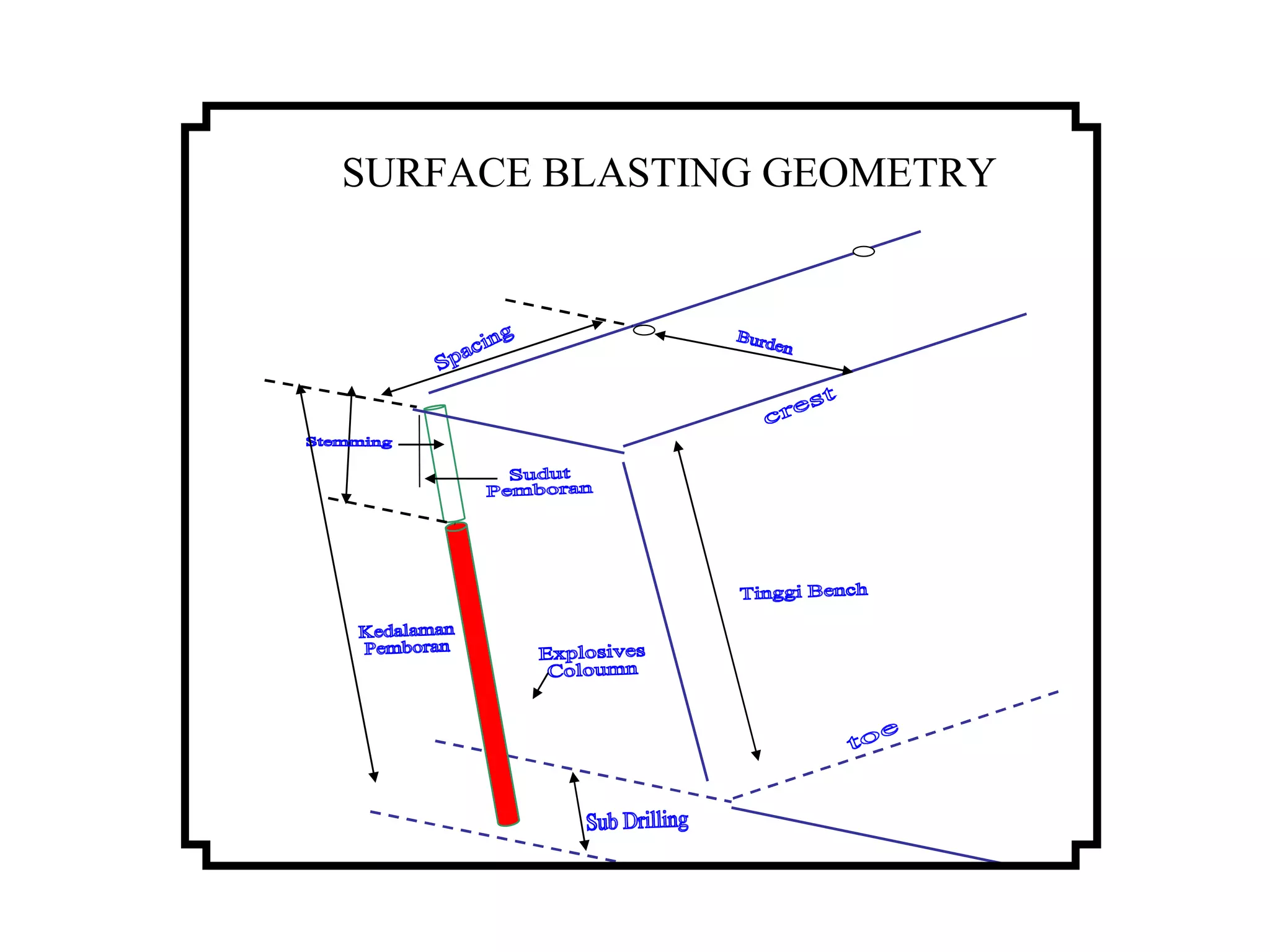
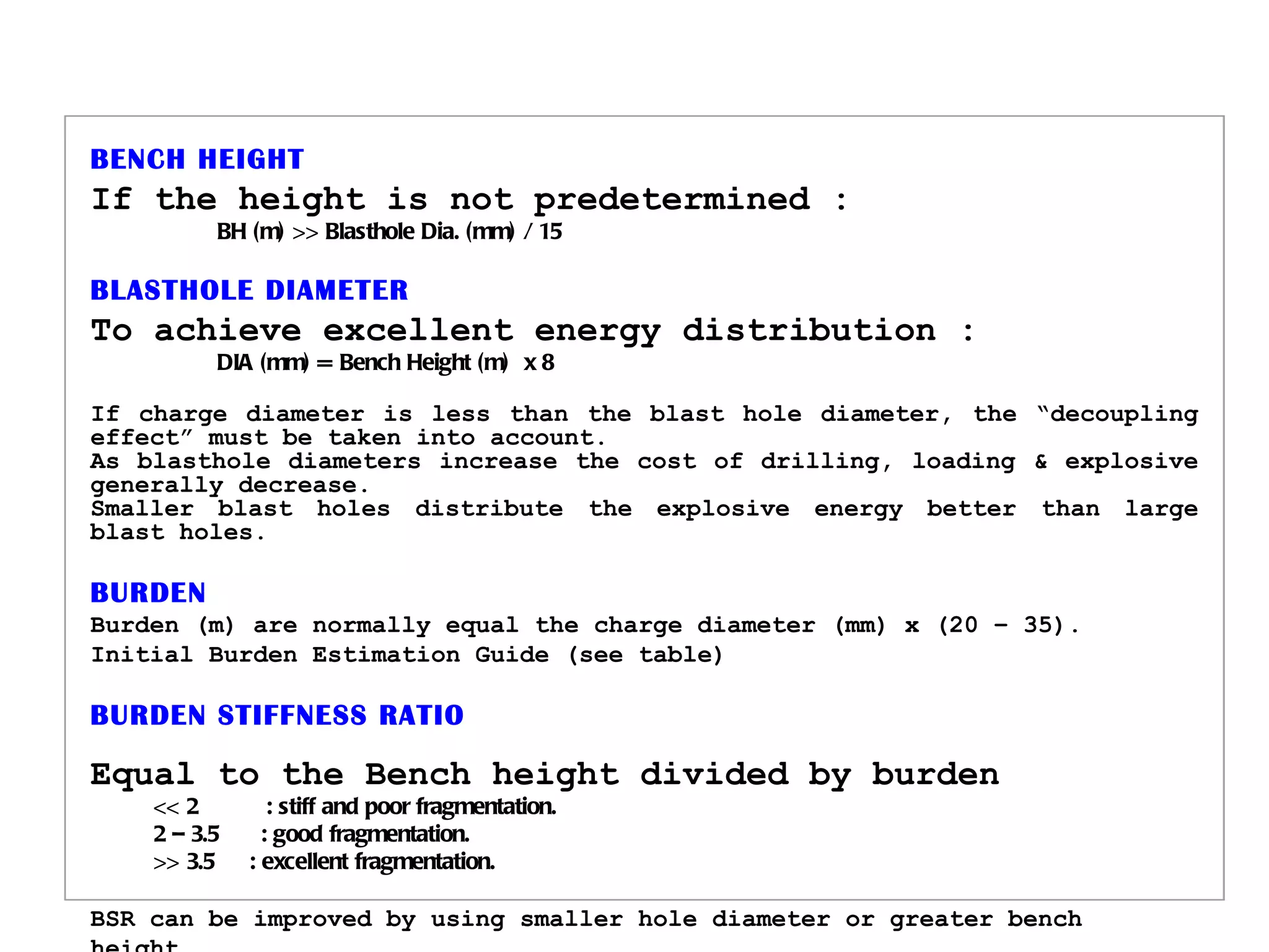
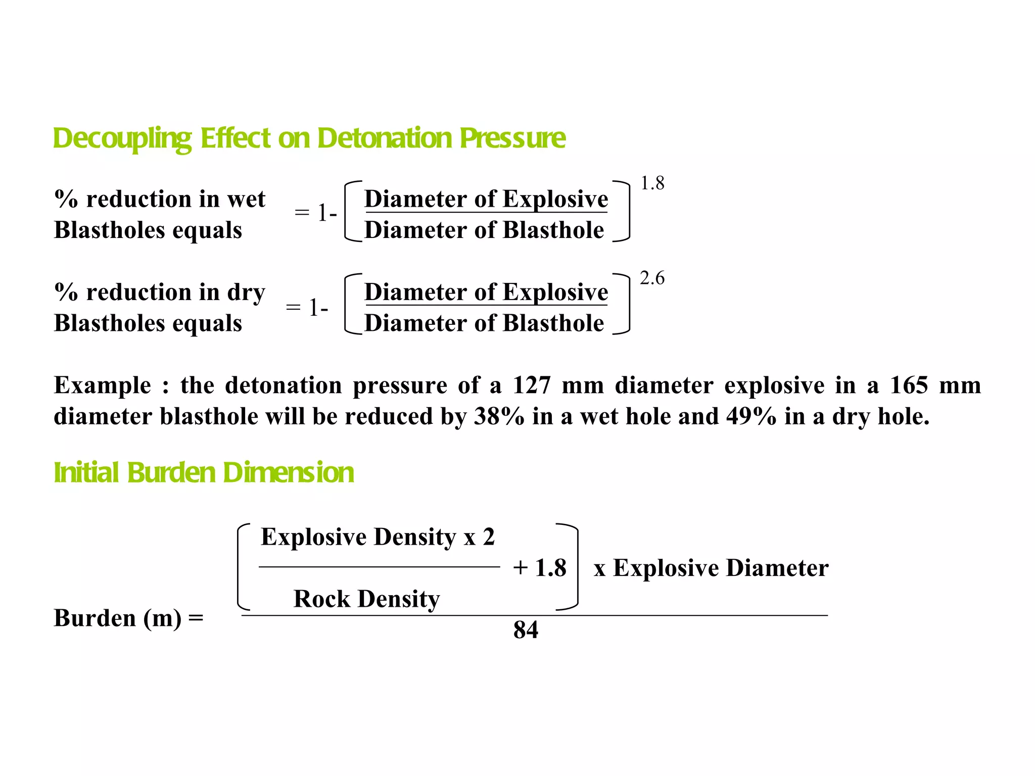
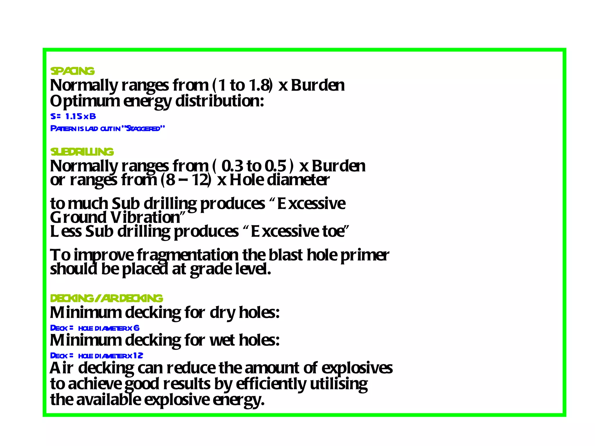
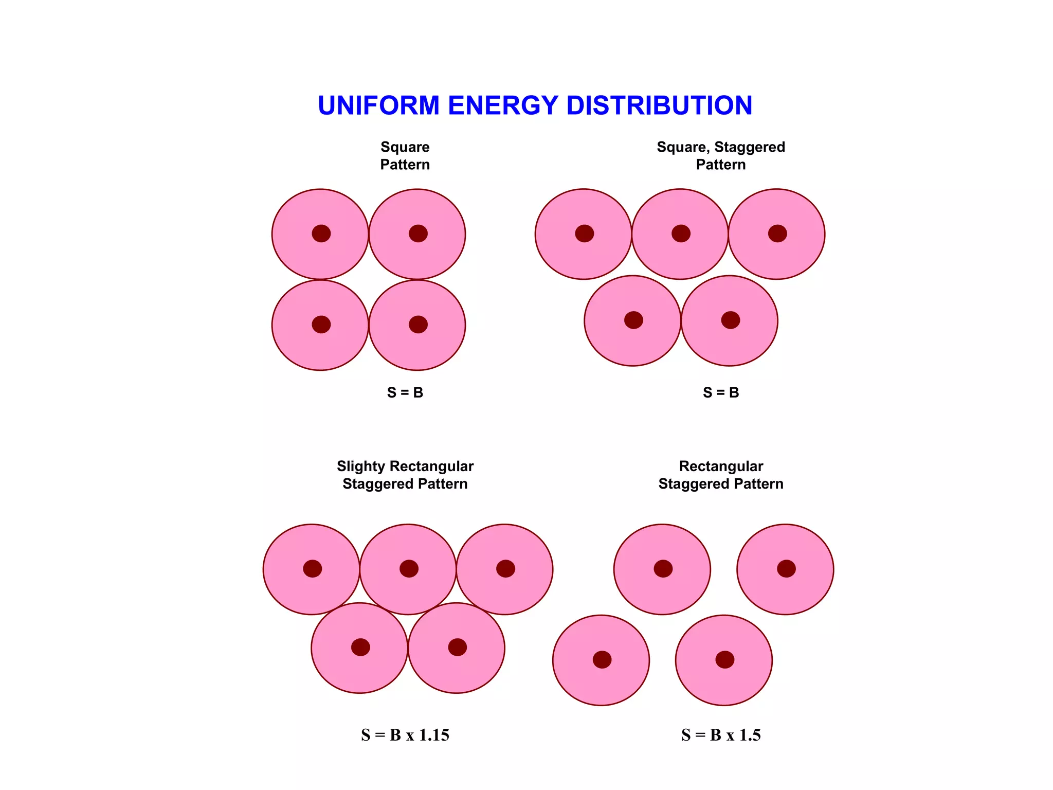
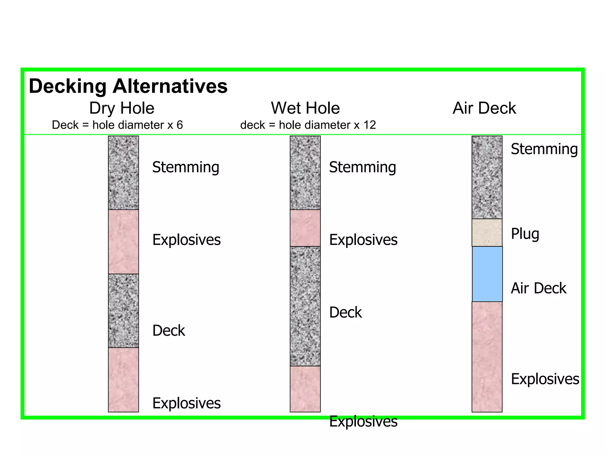
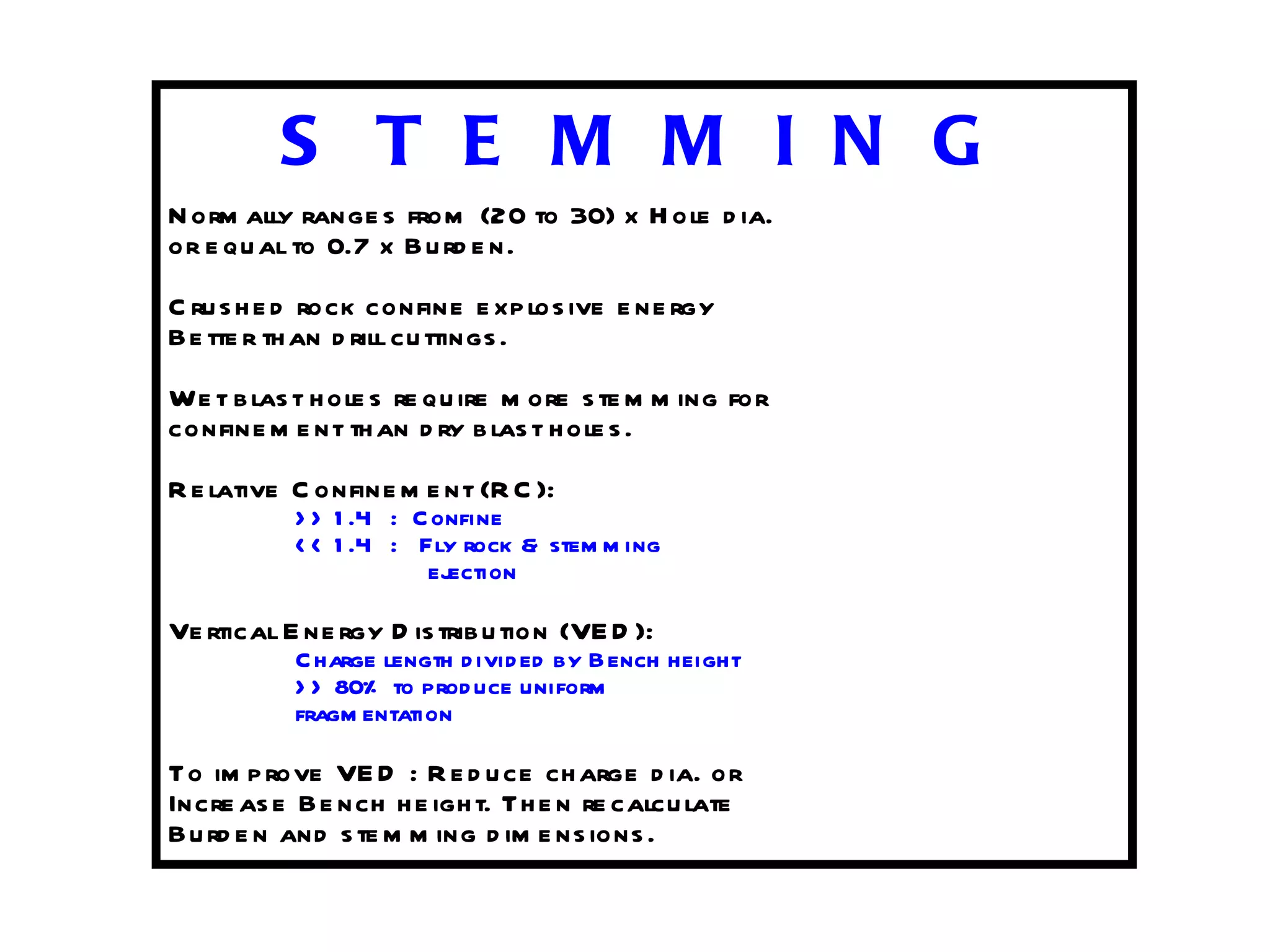
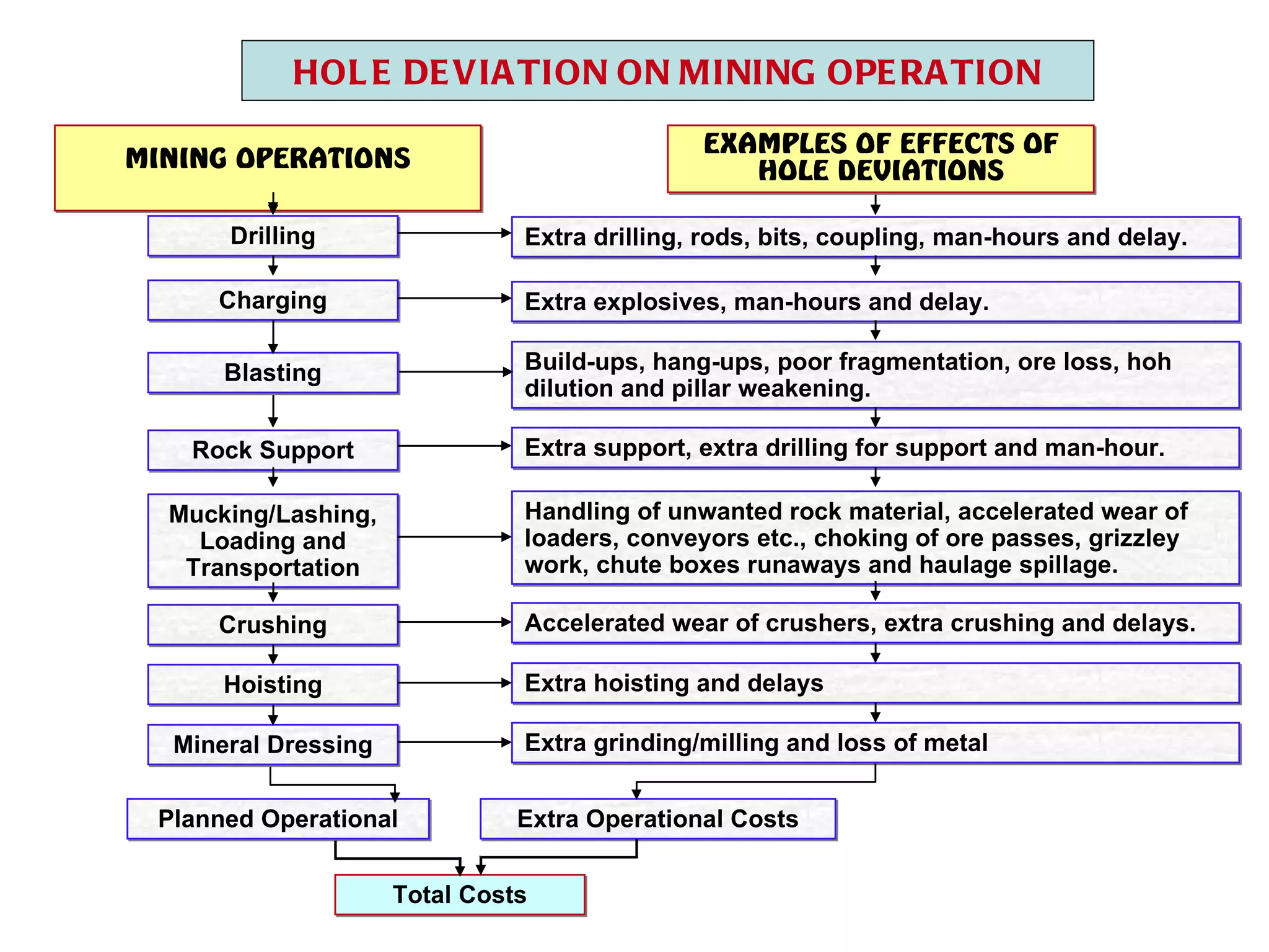

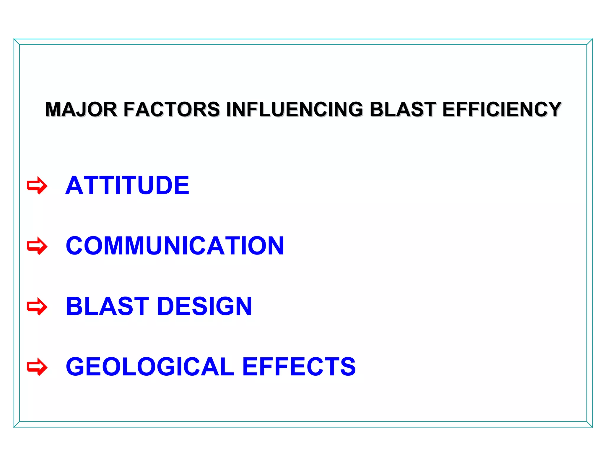
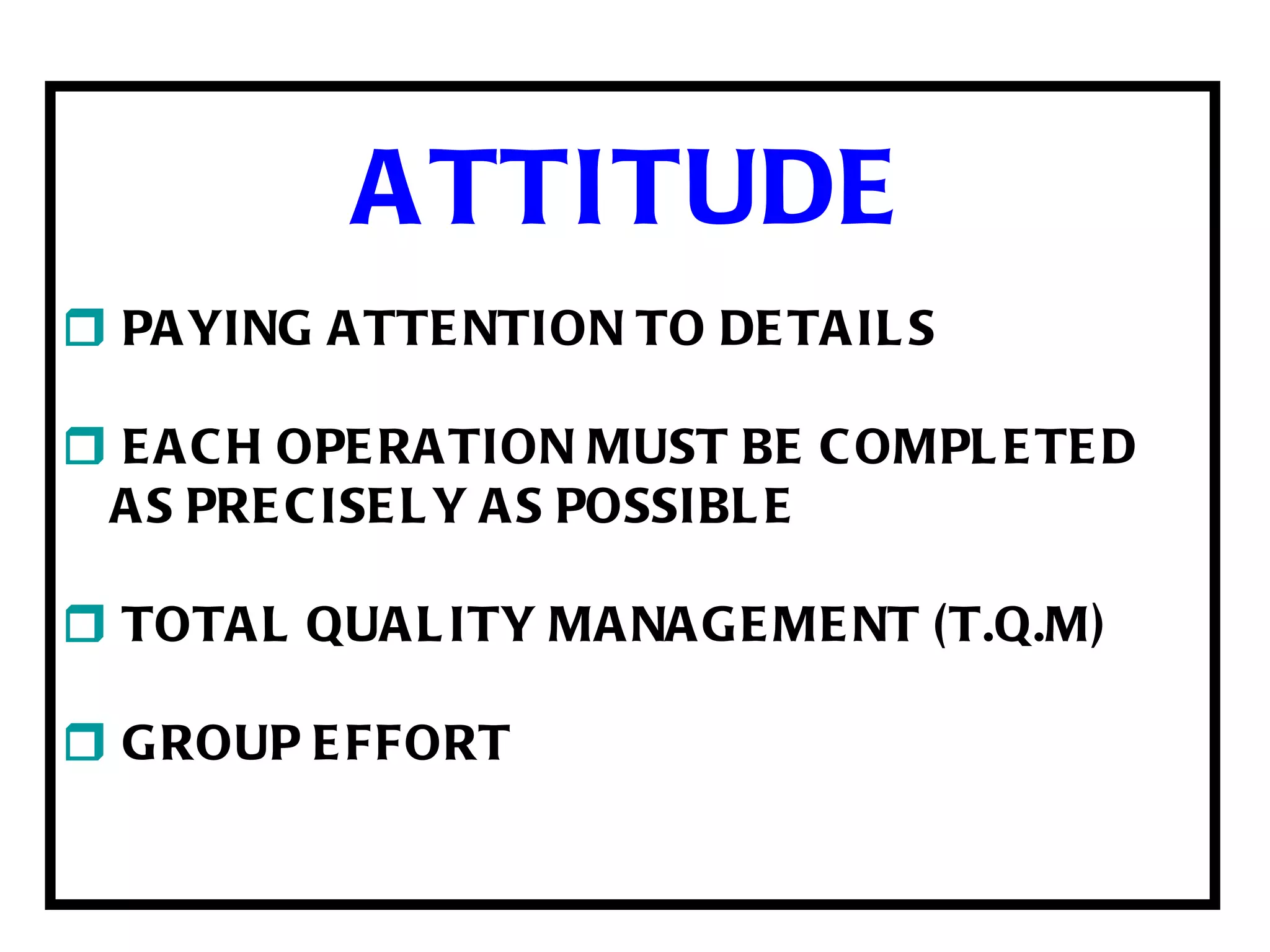
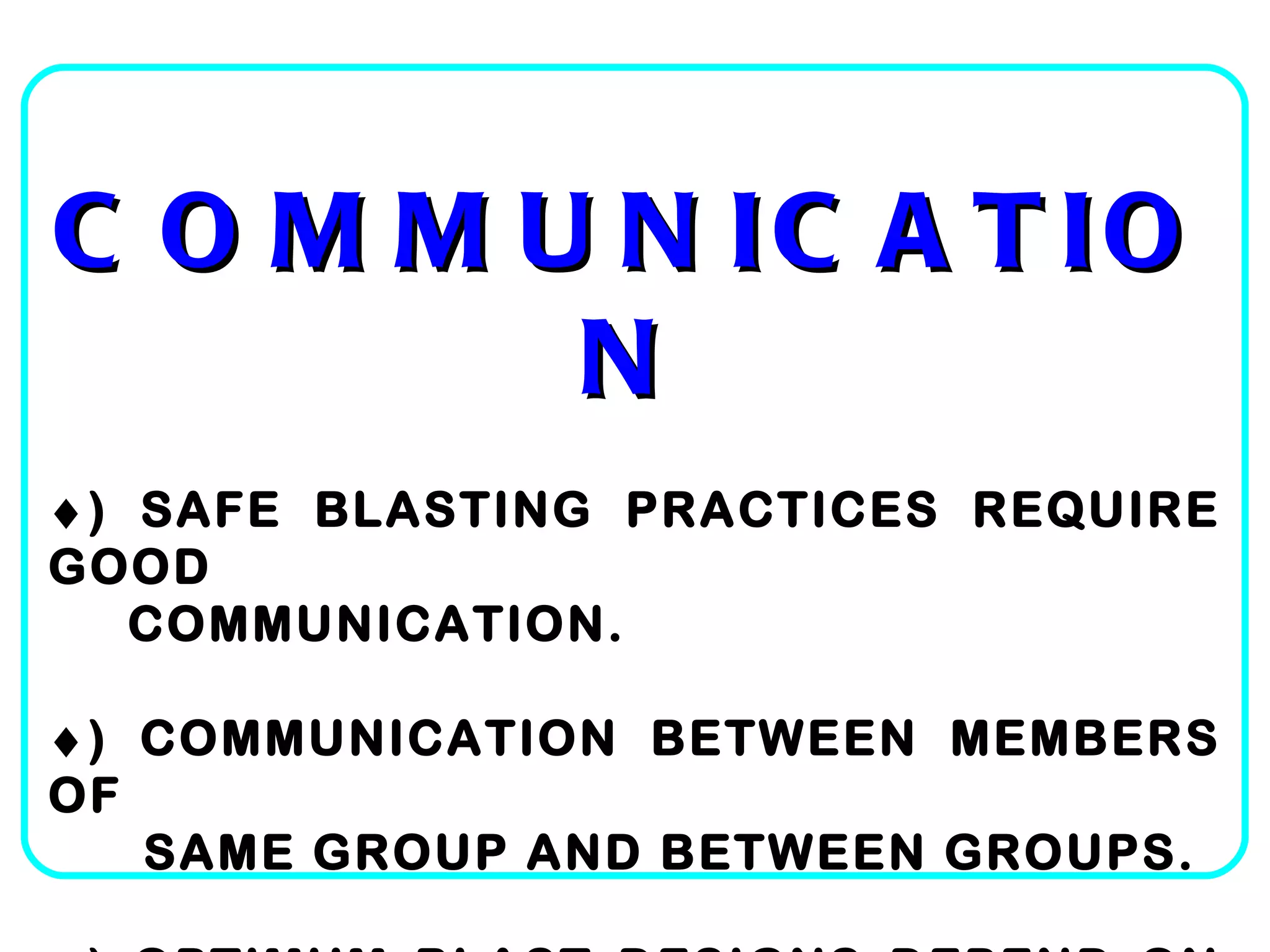
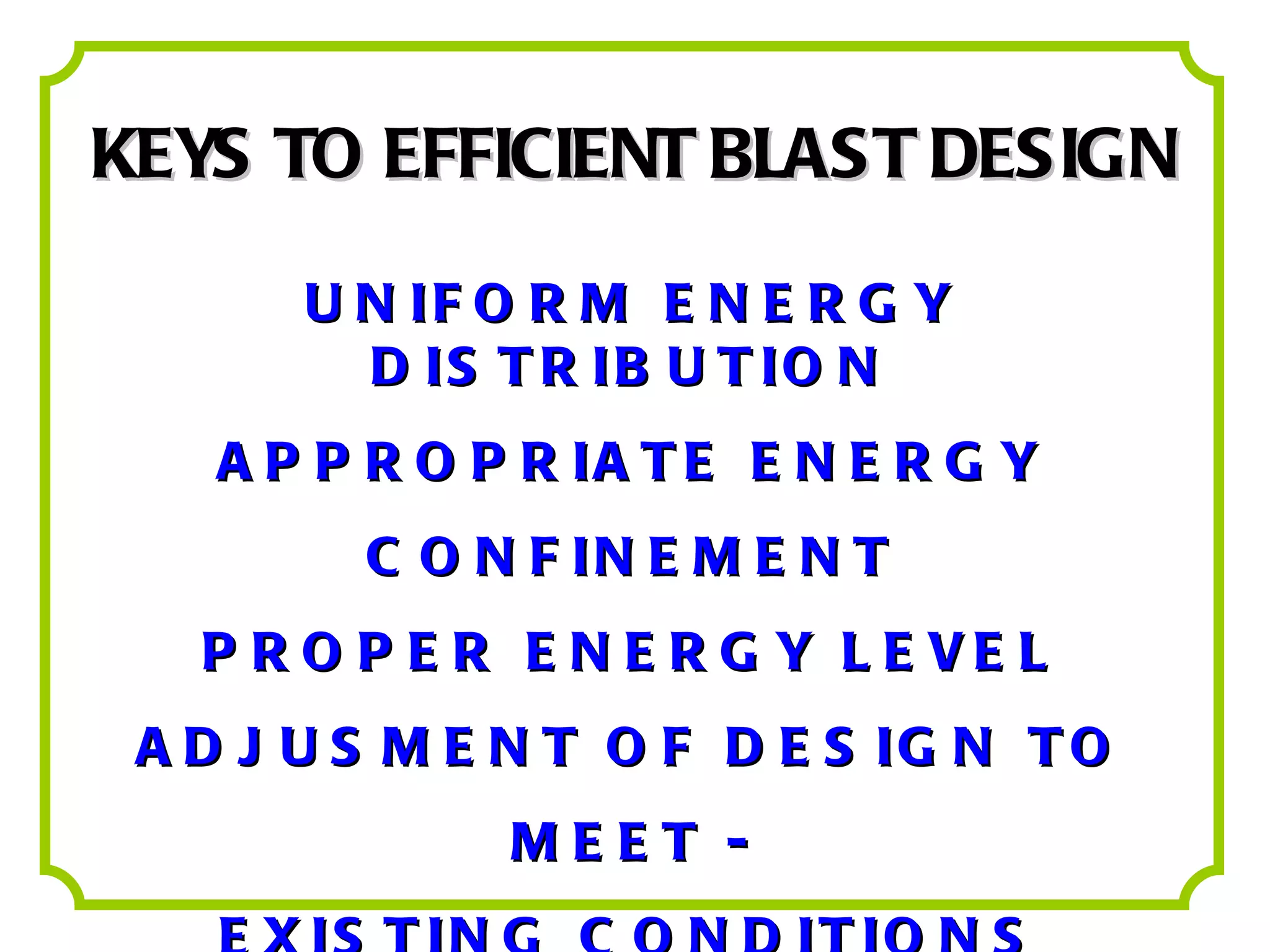
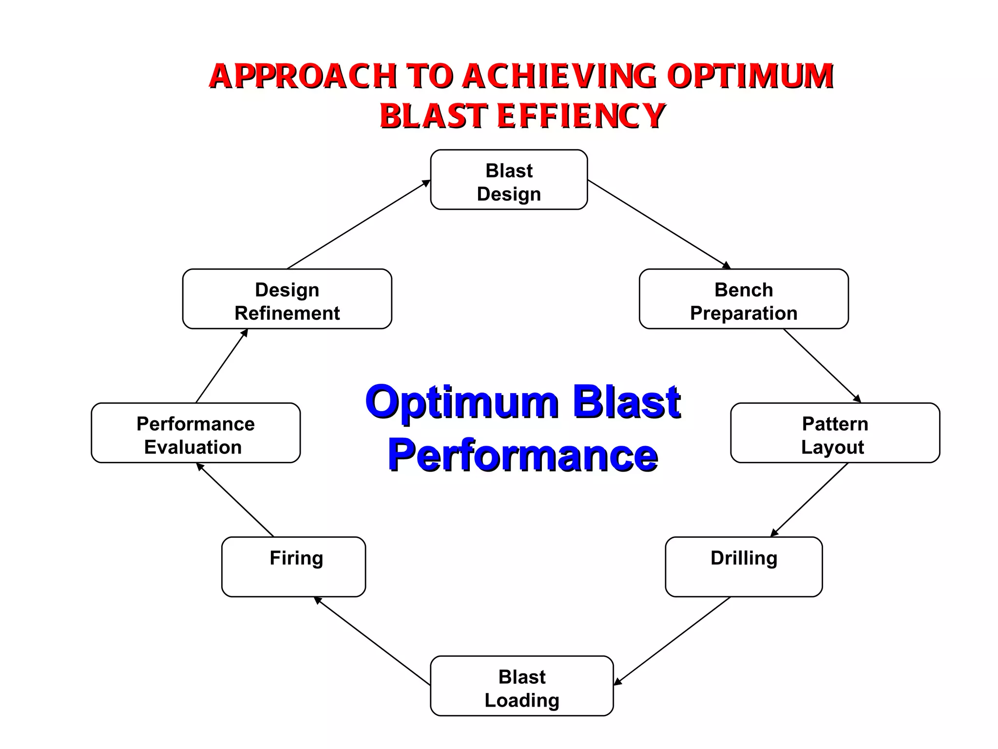
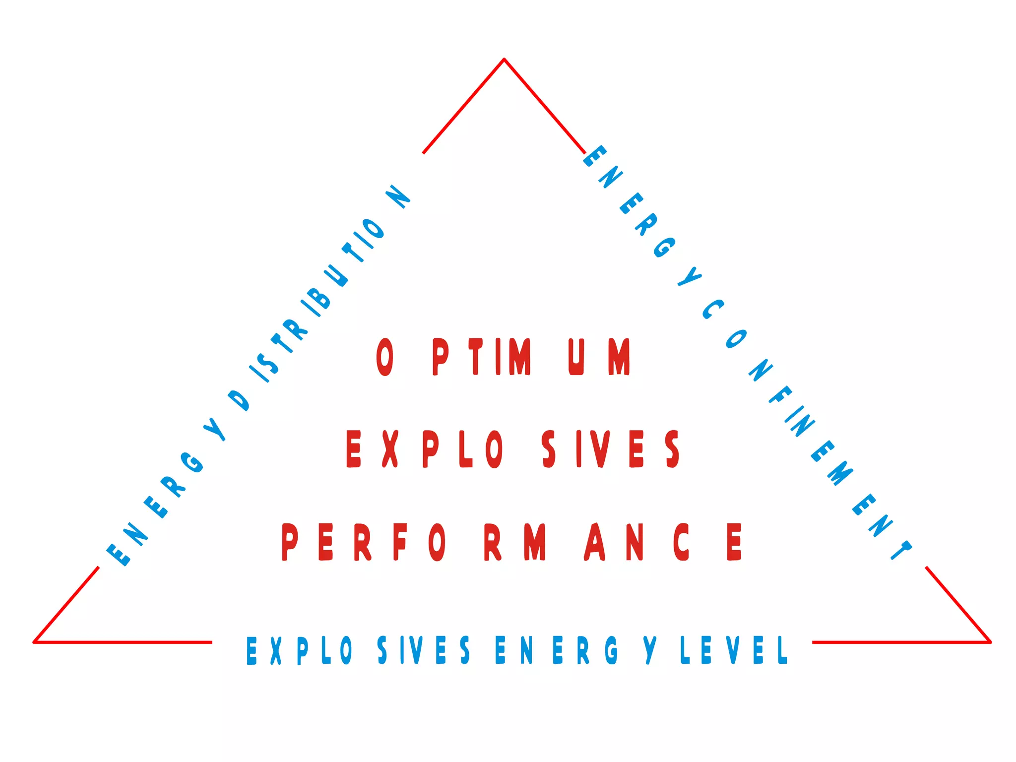
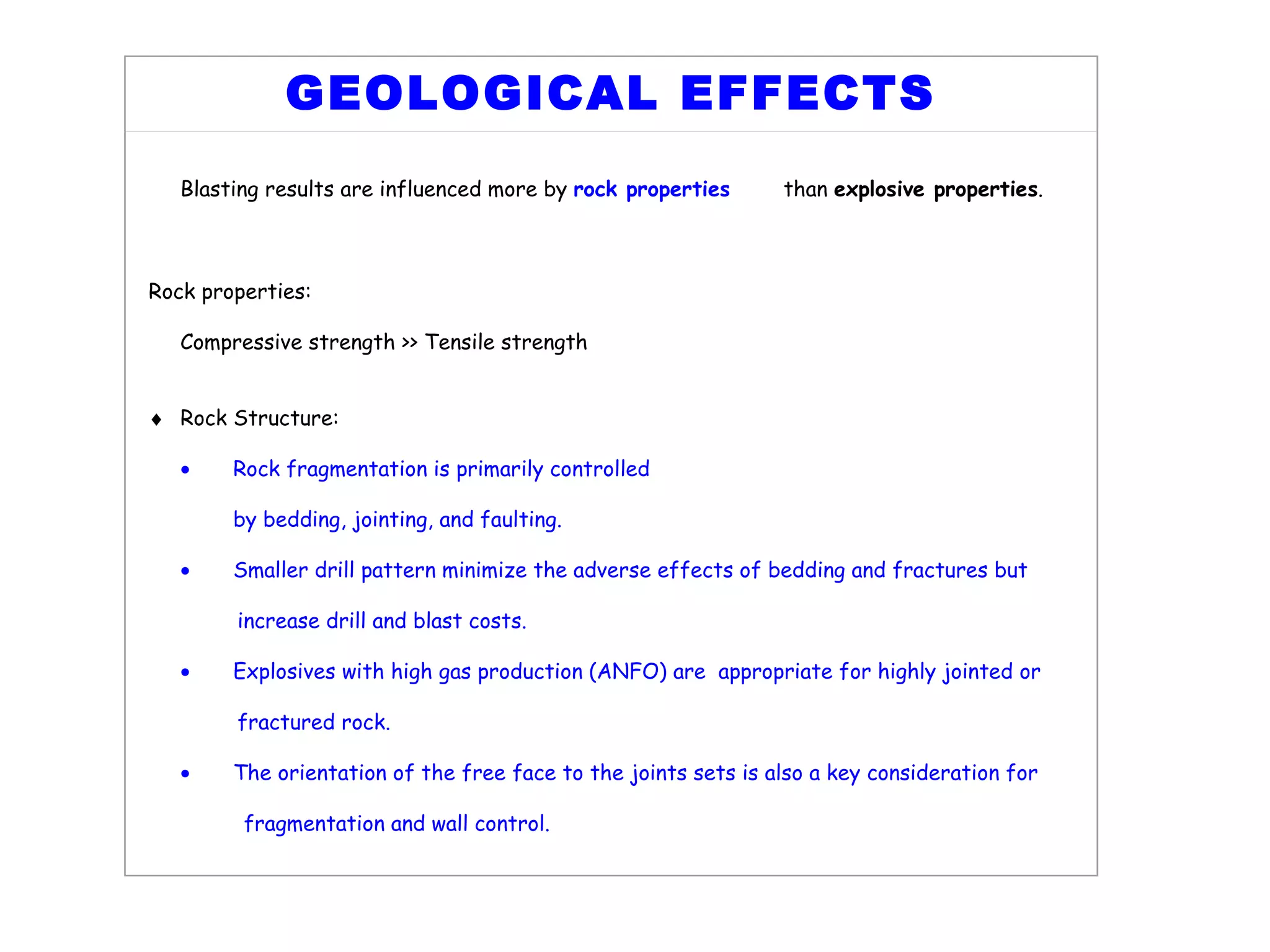
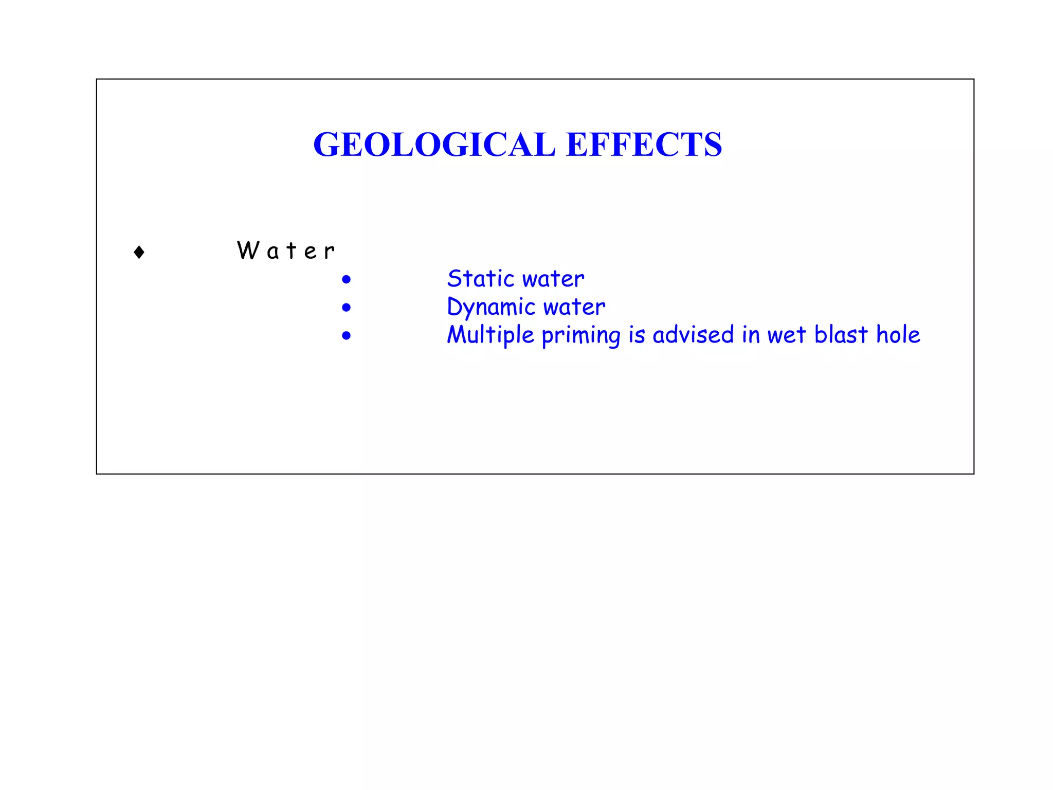
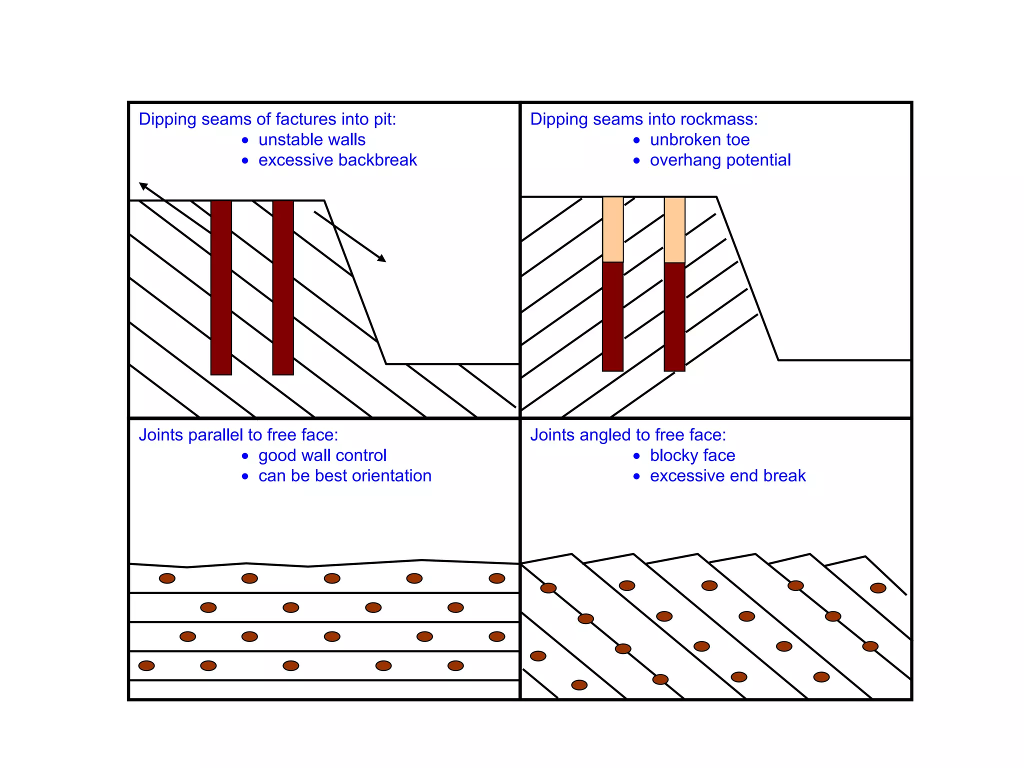
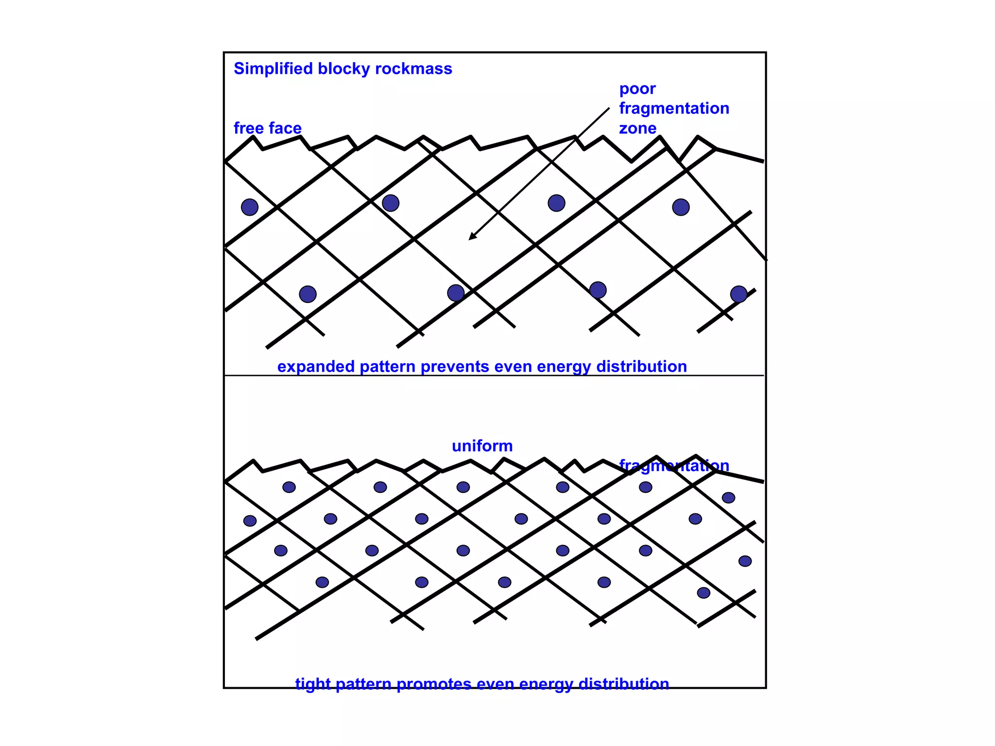
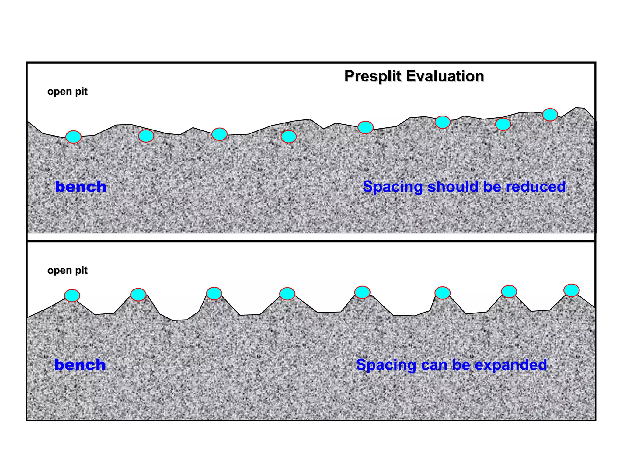
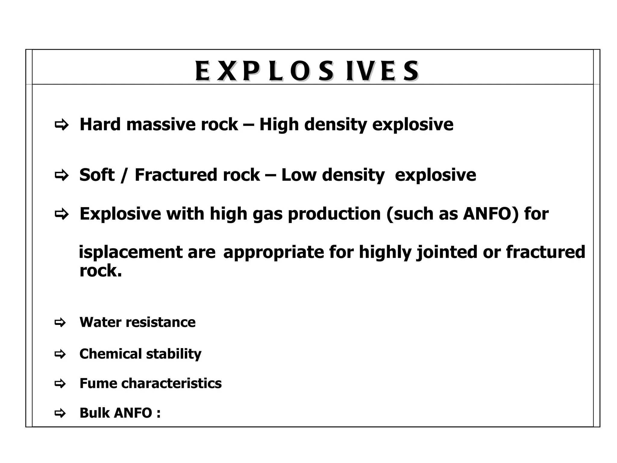
The document discusses techniques for open pit mining blasts, including: - Major factors like attitude, communication, blast design, and geological effects influence blast efficiency - Proper blast design considers uniform energy distribution, confinement, energy level, and design adjustments for conditions - Geological effects like rock properties, structure, water, and seam orientations impact blasting results more than explosive properties - Basic blast design considerations include bench height, hole diameter, burden, spacing, stemming, and decking