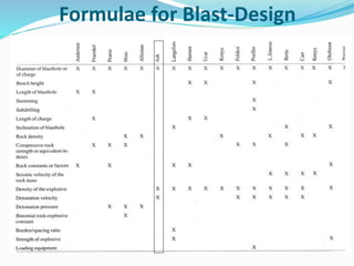
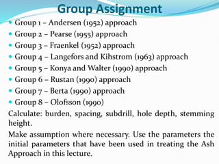
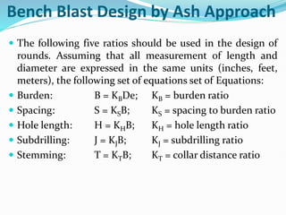
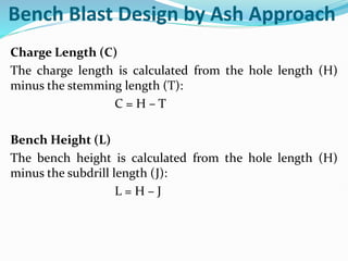
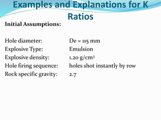
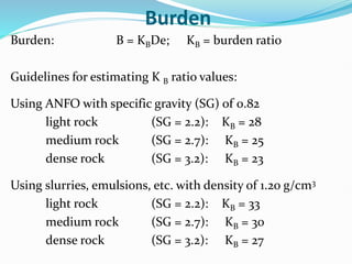
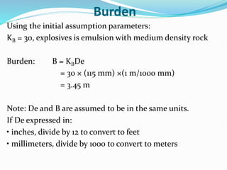
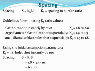
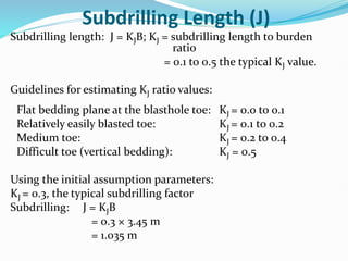
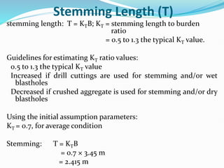
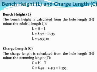
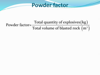
Presented by:
Dr Clement Kweku Arthur
Learning Objective
 Having worked through this chapter, the student will be
able to:
 Know and understand the factors that influence a
blast design;
 Describe the various Bench Blast Design Component;
and
 Compute the values for the Bench Blast Design
Component using the Ash approach.
Background
 In order to achieve optimum results from the explosive
energy, the blast designed has to balance all the
parameters that contribute to the desired
fragmentation.
 The blastholes must be arranged in the desired
manner with the correct depth, the right
amount/quantity of explosive must be placed into the
holes and the appropriate initiating technique/system
must be used to effect the detonation.
Factors Affecting Blast Design
 There are several factors that affect the results of a
blast and therefore, their design. These factors may be
generally, classified into two main groups. These are:
 Uncontrollable Factors or Variables
 Controllable Factors or Variables
Uncontrollable Factors
 These are the geological factors that are out of the
control of the Blaster.
 However, the Blaster's knowledge of the geology of the
area being blasted will help him place values on the
controllable factors to safely achieve the desired
fragmentation at a minimum cost.
 Such geological factors as the structure (fissures,
faults, fractures, joint planes, cavities/voids and mud-
seams), compressive and tensile strength, density and
porosity have profound effects on blast results.
Uncontrollable Factors
 For example, knowledge of the rock structure helps in
selecting a blast hole diameter and therefore a drilling
pattern that will produce fine fragmentation.
 The discontinuities also present a lot of problems for
drilling and blasting operations, because they provide
channels through which in drilling compressed air
energy is dissipated causing reduction in drill
penetration, while at the same time they provide
openings along which much of the explosive energy is
lost in the case of blasting, and thereby resulting in
coarser fragmentation with consequent higher costs of
production.
Controllable Factors
 These are factors over which the Blaster can exercise
control and therefore can balance them in their
selection to achieve the desired results.
 The variable factors include: hole diameter, burden,
spacing, stemming and the firing system.
 These variables are mutually interdependent, i.e., the
results of one affect those of the others.
 Controllable parameters in blast design can be grouped
into geometrical and explosive parameters
Bench Blast Design Component
Burden
 The burden is defined as the distance from the first row of
holes to the face of the excavation (free face) or between
rows in the usual case where rows are fired in sequence.
 The selection of this parameter is one of the most
important decisions to be made in blast design.
 Too small burdens result in a throw over considerable
distance, high airblast levels and excessively fine
fragmentation.
 Too large burdens may also result in severe backbreak,
over confinement of the explosives which can cause high
ground vibrations and extremely coarse fragmentation.
 It can also result in toe formation.
 Of all the parameters of blast design, the burden has the
least allowable error.
Spacing
 The spacing is defined as the distance between any two
adjacent charges in the same row and controls the mutual stress
effect between charges.
 It is an important blast geometrical parameter whose value
depends on the burden, hole depth, relative primer location
between adjacent charges and initiation time interval.
 When the spacing is appreciably less than the burden,
premature splitting between the blastholes and early loosening
of the stemming material tend to occur.
 This causes a rapid release of the explosive gases at high
pressure into the atmosphere (which can lead to high airblast
and noise levels) and considerable backbreak. When the
spacing to burden ratio is too high, adjacent charges cannot
interact well to break the intact rock between them.
 This will result in boulder formation
Subdrilling/subgrade drilling
 Subgrade drilling or subdrilling is the length of the
explosive charge, which lies beneath the designed bench
floor level (Anon., 2012).
 This is usually done to prevent toe formation which leads
to increased loading and haulage costs and slows down
production activities.
 According to Mishra (2009), the optimum effective
subdrill depends on the structural formation, density of
the rock, type of explosive, blasthole diameter and
inclination, effective burden and location of initiators in
the charge.
Hole Diameter
 The drill hole diameter is selected to give the required
fragmentation for loading, hauling and processing, and to
meet the production requirements.
 The hole diameter plays an important role in the
distribution of explosives in a given blast.
 Small diameter holes give a better distribution of explosive
energy and hence require lower powder factors.
 Small diameter holes are also good in highly jointed rocks.
However, the cost of drilling, priming and initiation are
high.
 Larger hole diameters give reliable explosive detonation,
higher shock energy, lower drilling and blasting cost, and
higher productivities
Hole Diameter
 Larger diameter holes however require higher powder
factors and may also cause boulders at the collar region
since stemming is usually higher.
 The selection of the hole diameter depends on the bench
height, machines available, degree of fragmentation
required, type of explosives, rock properties and required
production per hour.
Stemming Height and Material
 Stemming height refers to the height/length of the
blasthole which is normally filled with inert material to
confine the explosive gases.
 Stemming is done to confine the explosive to ensure that
the explosive energy is used to fragment the rock before it
escapes from the formation.
 Adequate stemming is also required to control excessive
airblast and flyrock.
 When the formation to be blasted is highly fractured or
has several planes of weakness, relatively long stemming
height can be used to ensure optimal fragmentation.
 When the rock is competent and massive, the stemming
should be shortest to give good fragmentation results and
also minimise excessive noise, airblast and backbreak.
Stemming Height and Material
 The type and amount of stemming material used has an
influence on the degree of confinement and the efficiency
of the blast.
 In order to extract the maximum energy from the
expanding gases, the stemming plug should never blow
out and allow the gases to escape prematurely (before
fragmentation and throw) (Muhammad, 2009).
 The recommended stemming material is dry angular
crushed rock (< 30 mm) as it tends to form a compaction
arch, which locks into the blasthole wall, increasing its
resistance to ejection (Anon., 2005).
 However, it is common for drill cuttings to be used due to
their availability and nearness to the hole collar.
Powder factor
 The powder factor is defined as the amount of explosives
per cubic meter or tonne of blasted material. It can serve
as an indication of rock hardness, cost of explosives
needed or as a guide to planning a blast.
Formulae for Blast-Design
Group Assignment
 Group 1 – Andersen (1952) approach
 Group 2 – Pearse (1955) approach
 Group 3 – Fraenkel (1952) approach
 Group 4 – Langefors and Kihstrom (1963) approach
 Group 5 – Konya and Walter (1990) approach
 Group 6 – Rustan (1990) approach
 Group 7 – Berta (1990) approach
 Group 8 – Olofsson (1990)
Calculate: burden, spacing, subdrill, hole depth, stemming
height.
Make assumption where necessary. Use the parameters the
initial parameters that have been used in treating the Ash
Approach in this lecture.
Bench Blast Design by Ash Approach
 The following five ratios should be used in the design of
rounds. Assuming that all measurement of length and
diameter are expressed in the same units (inches, feet,
meters), the following set of equations set of Equations:
 Burden: B = KBDe; KB = burden ratio
 Spacing: S = KSB; KS = spacing to burden ratio
 Hole length: H = KHB; KH = hole length ratio
 Subdrilling: J = KJB; KJ = subdrilling ratio
 Stemming: T = KTB; KT = collar distance ratio
Bench Blast Design by Ash Approach
Charge Length (C)
The charge length is calculated from the hole length (H)
minus the stemming length (T):
C = H – T
Bench Height (L)
The bench height is calculated from the hole length (H)
minus the subdrill length (J):
L = H – J
Examples and Explanations for K
Ratios
Initial Assumptions:
Hole diameter: De = 115 mm
Explosive Type: Emulsion
Explosive density: 1.20 g/cm3
Hole firing sequence: holes shot instantly by row
Rock specific gravity: 2.7
Burden
Burden: B = KBDe; KB = burden ratio
Guidelines for estimating K B ratio values:
Using ANFO with specific gravity (SG) of 0.82
light rock (SG = 2.2): KB = 28
medium rock (SG = 2.7): KB = 25
dense rock (SG = 3.2): KB = 23
Using slurries, emulsions, etc. with density of 1.20 g/cm3
light rock (SG = 2.2): KB = 33
medium rock (SG = 2.7): KB = 30
dense rock (SG = 3.2): KB = 27
Burden
Using the initial assumption parameters:
KB = 30, explosives is emulsion with medium density rock
Burden: B = KBDe
= 30 × (115 mm) ×(1 m/1000 mm)
= 3.45 m
Note: De and B are assumed to be in the same units.
If De expressed in:
• inches, divide by 12 to convert to feet
• millimeters, divide by 1000 to convert to meters
Spacing
Spacing: S = KSB; KS = spacing to burden ratio
Guidelines for estimating KS ratio values:
blastholes shot instantly by row: KS = 1.8 to 2.0
large diameter blastholes shot sequentially: KS = 1.2 to 1.5
small diameter blastholes shot sequentially: KS = 1.5 to 1.8
Using the initial assumption parameters:
KS = 1.8, holes shot instantly by row
Spacing: S = KSB
= 1.8 × 3.45 m
= 6.21 m
Hole Length (H)
Hole length: H = KHB; KH = hole length to burden ratio
= 1.5 to 4.0 with 2.6 the typical
KH value.
The depth should almost always be greater than or equal to
the burden to reduce overbreak and cratering tendencies.
Conversely, high values, greater than 4.0, may create
underbreak or bootlegging if the hole is single primed.
Using the initial assumption parameters:
KS = 1.8, holes shot instantly by row
Hole Length: H = KHB
= 2.6 × 3.45 m
= 8.97 m
Subdrilling Length (J)
Subdrilling length: J = KJB; KJ = subdrilling length to burden
ratio
= 0.1 to 0.5 the typical KJ value.
Guidelines for estimating KJ ratio values:
Flat bedding plane at the blasthole toe: KJ = 0.0 to 0.1
Relatively easily blasted toe: KJ = 0.1 to 0.2
Medium toe: KJ = 0.2 to 0.4
Difficult toe (vertical bedding): KJ = 0.5
Using the initial assumption parameters:
KJ = 0.3, the typical subdrilling factor
Subdrilling: J = KJB
= 0.3 × 3.45 m
= 1.035 m
Stemming Length (T)
stemming length: T = KTB; KT = stemming length to burden
ratio
= 0.5 to 1.3 the typical KT value.
Guidelines for estimating KT ratio values:
0.5 to 1.3 the typical KT value
Increased if drill cuttings are used for stemming and/or wet
blastholes
Decreased if crushed aggregate is used for stemming and/or dry
blastholes
Using the initial assumption parameters:
KT = 0.7, for average condition
Stemming: T = KTB
= 0.7 × 3.45 m
= 2.415 m
Bench Height (L) and Charge Length (C)
Bench Height (L)
The bench height is calculated from the hole length (H)
minus the subdrill length (J):
L = H – J
L = 8.97 – 1.035
L = 7.935 m
Charge Length (C)
The charge length is calculated from the hole length (H)
minus the stemming length (T):
C = H – T
C = 8.97 – 2.415 = 6.555
Rock Volume
Rock volume per blasthole (VH)
The rock volume per blasthole is found from the burden (B),
spacing (S), and bench height (L) by:
VH = B × S × L
= 3.45 × 6.21 × 7.935
= 170.00 m3
Multiply the rock volume per blasthole to the total number
of holes blasted to get the total blasted rock volume.
Powder factor
( )
( )
3
Total quantity of explosives kg
Powder factor=
Total volume of blasted rock m
Basic Steps to Successful Blast Design
 The following procedures should be followed for a successful blast.
 Theoretically, determine design parameters based on empirical
rules/formulae.
 Propose some initial design.
 Observe the performance of this blast, i.e.
 Size distribution (quality of fragmentation).
 Performance of loading equipment/machine.
 Bench conditions (toes, misfires, sockets, over-break, etc).
 Cost.
 Modify the design and assess again until the desired results are
obtained.
 Always remember that the blast design must necessarily change to meet
changing ground conditions.
QUESTION TIME
???

Surface Blast Design_082519.pdf

  • 1.
  • 2.
    Learning Objective  Havingworked through this chapter, the student will be able to:  Know and understand the factors that influence a blast design;  Describe the various Bench Blast Design Component; and  Compute the values for the Bench Blast Design Component using the Ash approach.
  • 3.
    Background  In orderto achieve optimum results from the explosive energy, the blast designed has to balance all the parameters that contribute to the desired fragmentation.  The blastholes must be arranged in the desired manner with the correct depth, the right amount/quantity of explosive must be placed into the holes and the appropriate initiating technique/system must be used to effect the detonation.
  • 4.
    Factors Affecting BlastDesign  There are several factors that affect the results of a blast and therefore, their design. These factors may be generally, classified into two main groups. These are:  Uncontrollable Factors or Variables  Controllable Factors or Variables
  • 5.
    Uncontrollable Factors  Theseare the geological factors that are out of the control of the Blaster.  However, the Blaster's knowledge of the geology of the area being blasted will help him place values on the controllable factors to safely achieve the desired fragmentation at a minimum cost.  Such geological factors as the structure (fissures, faults, fractures, joint planes, cavities/voids and mud- seams), compressive and tensile strength, density and porosity have profound effects on blast results.
  • 6.
    Uncontrollable Factors  Forexample, knowledge of the rock structure helps in selecting a blast hole diameter and therefore a drilling pattern that will produce fine fragmentation.  The discontinuities also present a lot of problems for drilling and blasting operations, because they provide channels through which in drilling compressed air energy is dissipated causing reduction in drill penetration, while at the same time they provide openings along which much of the explosive energy is lost in the case of blasting, and thereby resulting in coarser fragmentation with consequent higher costs of production.
  • 7.
    Controllable Factors  Theseare factors over which the Blaster can exercise control and therefore can balance them in their selection to achieve the desired results.  The variable factors include: hole diameter, burden, spacing, stemming and the firing system.  These variables are mutually interdependent, i.e., the results of one affect those of the others.  Controllable parameters in blast design can be grouped into geometrical and explosive parameters
  • 8.
  • 9.
  • 10.
    Burden  The burdenis defined as the distance from the first row of holes to the face of the excavation (free face) or between rows in the usual case where rows are fired in sequence.  The selection of this parameter is one of the most important decisions to be made in blast design.  Too small burdens result in a throw over considerable distance, high airblast levels and excessively fine fragmentation.  Too large burdens may also result in severe backbreak, over confinement of the explosives which can cause high ground vibrations and extremely coarse fragmentation.  It can also result in toe formation.  Of all the parameters of blast design, the burden has the least allowable error.
  • 11.
    Spacing  The spacingis defined as the distance between any two adjacent charges in the same row and controls the mutual stress effect between charges.  It is an important blast geometrical parameter whose value depends on the burden, hole depth, relative primer location between adjacent charges and initiation time interval.  When the spacing is appreciably less than the burden, premature splitting between the blastholes and early loosening of the stemming material tend to occur.  This causes a rapid release of the explosive gases at high pressure into the atmosphere (which can lead to high airblast and noise levels) and considerable backbreak. When the spacing to burden ratio is too high, adjacent charges cannot interact well to break the intact rock between them.  This will result in boulder formation
  • 12.
    Subdrilling/subgrade drilling  Subgradedrilling or subdrilling is the length of the explosive charge, which lies beneath the designed bench floor level (Anon., 2012).  This is usually done to prevent toe formation which leads to increased loading and haulage costs and slows down production activities.  According to Mishra (2009), the optimum effective subdrill depends on the structural formation, density of the rock, type of explosive, blasthole diameter and inclination, effective burden and location of initiators in the charge.
  • 13.
    Hole Diameter  Thedrill hole diameter is selected to give the required fragmentation for loading, hauling and processing, and to meet the production requirements.  The hole diameter plays an important role in the distribution of explosives in a given blast.  Small diameter holes give a better distribution of explosive energy and hence require lower powder factors.  Small diameter holes are also good in highly jointed rocks. However, the cost of drilling, priming and initiation are high.  Larger hole diameters give reliable explosive detonation, higher shock energy, lower drilling and blasting cost, and higher productivities
  • 14.
    Hole Diameter  Largerdiameter holes however require higher powder factors and may also cause boulders at the collar region since stemming is usually higher.  The selection of the hole diameter depends on the bench height, machines available, degree of fragmentation required, type of explosives, rock properties and required production per hour.
  • 15.
    Stemming Height andMaterial  Stemming height refers to the height/length of the blasthole which is normally filled with inert material to confine the explosive gases.  Stemming is done to confine the explosive to ensure that the explosive energy is used to fragment the rock before it escapes from the formation.  Adequate stemming is also required to control excessive airblast and flyrock.  When the formation to be blasted is highly fractured or has several planes of weakness, relatively long stemming height can be used to ensure optimal fragmentation.  When the rock is competent and massive, the stemming should be shortest to give good fragmentation results and also minimise excessive noise, airblast and backbreak.
  • 16.
    Stemming Height andMaterial  The type and amount of stemming material used has an influence on the degree of confinement and the efficiency of the blast.  In order to extract the maximum energy from the expanding gases, the stemming plug should never blow out and allow the gases to escape prematurely (before fragmentation and throw) (Muhammad, 2009).  The recommended stemming material is dry angular crushed rock (< 30 mm) as it tends to form a compaction arch, which locks into the blasthole wall, increasing its resistance to ejection (Anon., 2005).  However, it is common for drill cuttings to be used due to their availability and nearness to the hole collar.
  • 17.
    Powder factor  Thepowder factor is defined as the amount of explosives per cubic meter or tonne of blasted material. It can serve as an indication of rock hardness, cost of explosives needed or as a guide to planning a blast.
  • 18.
  • 19.
    Group Assignment  Group1 – Andersen (1952) approach  Group 2 – Pearse (1955) approach  Group 3 – Fraenkel (1952) approach  Group 4 – Langefors and Kihstrom (1963) approach  Group 5 – Konya and Walter (1990) approach  Group 6 – Rustan (1990) approach  Group 7 – Berta (1990) approach  Group 8 – Olofsson (1990) Calculate: burden, spacing, subdrill, hole depth, stemming height. Make assumption where necessary. Use the parameters the initial parameters that have been used in treating the Ash Approach in this lecture.
  • 20.
    Bench Blast Designby Ash Approach  The following five ratios should be used in the design of rounds. Assuming that all measurement of length and diameter are expressed in the same units (inches, feet, meters), the following set of equations set of Equations:  Burden: B = KBDe; KB = burden ratio  Spacing: S = KSB; KS = spacing to burden ratio  Hole length: H = KHB; KH = hole length ratio  Subdrilling: J = KJB; KJ = subdrilling ratio  Stemming: T = KTB; KT = collar distance ratio
  • 21.
    Bench Blast Designby Ash Approach Charge Length (C) The charge length is calculated from the hole length (H) minus the stemming length (T): C = H – T Bench Height (L) The bench height is calculated from the hole length (H) minus the subdrill length (J): L = H – J
  • 22.
    Examples and Explanationsfor K Ratios Initial Assumptions: Hole diameter: De = 115 mm Explosive Type: Emulsion Explosive density: 1.20 g/cm3 Hole firing sequence: holes shot instantly by row Rock specific gravity: 2.7
  • 23.
    Burden Burden: B =KBDe; KB = burden ratio Guidelines for estimating K B ratio values: Using ANFO with specific gravity (SG) of 0.82 light rock (SG = 2.2): KB = 28 medium rock (SG = 2.7): KB = 25 dense rock (SG = 3.2): KB = 23 Using slurries, emulsions, etc. with density of 1.20 g/cm3 light rock (SG = 2.2): KB = 33 medium rock (SG = 2.7): KB = 30 dense rock (SG = 3.2): KB = 27
  • 24.
    Burden Using the initialassumption parameters: KB = 30, explosives is emulsion with medium density rock Burden: B = KBDe = 30 × (115 mm) ×(1 m/1000 mm) = 3.45 m Note: De and B are assumed to be in the same units. If De expressed in: • inches, divide by 12 to convert to feet • millimeters, divide by 1000 to convert to meters
  • 25.
    Spacing Spacing: S =KSB; KS = spacing to burden ratio Guidelines for estimating KS ratio values: blastholes shot instantly by row: KS = 1.8 to 2.0 large diameter blastholes shot sequentially: KS = 1.2 to 1.5 small diameter blastholes shot sequentially: KS = 1.5 to 1.8 Using the initial assumption parameters: KS = 1.8, holes shot instantly by row Spacing: S = KSB = 1.8 × 3.45 m = 6.21 m
  • 26.
    Hole Length (H) Holelength: H = KHB; KH = hole length to burden ratio = 1.5 to 4.0 with 2.6 the typical KH value. The depth should almost always be greater than or equal to the burden to reduce overbreak and cratering tendencies. Conversely, high values, greater than 4.0, may create underbreak or bootlegging if the hole is single primed. Using the initial assumption parameters: KS = 1.8, holes shot instantly by row Hole Length: H = KHB = 2.6 × 3.45 m = 8.97 m
  • 27.
    Subdrilling Length (J) Subdrillinglength: J = KJB; KJ = subdrilling length to burden ratio = 0.1 to 0.5 the typical KJ value. Guidelines for estimating KJ ratio values: Flat bedding plane at the blasthole toe: KJ = 0.0 to 0.1 Relatively easily blasted toe: KJ = 0.1 to 0.2 Medium toe: KJ = 0.2 to 0.4 Difficult toe (vertical bedding): KJ = 0.5 Using the initial assumption parameters: KJ = 0.3, the typical subdrilling factor Subdrilling: J = KJB = 0.3 × 3.45 m = 1.035 m
  • 28.
    Stemming Length (T) stemminglength: T = KTB; KT = stemming length to burden ratio = 0.5 to 1.3 the typical KT value. Guidelines for estimating KT ratio values: 0.5 to 1.3 the typical KT value Increased if drill cuttings are used for stemming and/or wet blastholes Decreased if crushed aggregate is used for stemming and/or dry blastholes Using the initial assumption parameters: KT = 0.7, for average condition Stemming: T = KTB = 0.7 × 3.45 m = 2.415 m
  • 29.
    Bench Height (L)and Charge Length (C) Bench Height (L) The bench height is calculated from the hole length (H) minus the subdrill length (J): L = H – J L = 8.97 – 1.035 L = 7.935 m Charge Length (C) The charge length is calculated from the hole length (H) minus the stemming length (T): C = H – T C = 8.97 – 2.415 = 6.555
  • 30.
    Rock Volume Rock volumeper blasthole (VH) The rock volume per blasthole is found from the burden (B), spacing (S), and bench height (L) by: VH = B × S × L = 3.45 × 6.21 × 7.935 = 170.00 m3 Multiply the rock volume per blasthole to the total number of holes blasted to get the total blasted rock volume.
  • 31.
    Powder factor ( ) () 3 Total quantity of explosives kg Powder factor= Total volume of blasted rock m
  • 32.
    Basic Steps toSuccessful Blast Design  The following procedures should be followed for a successful blast.  Theoretically, determine design parameters based on empirical rules/formulae.  Propose some initial design.  Observe the performance of this blast, i.e.  Size distribution (quality of fragmentation).  Performance of loading equipment/machine.  Bench conditions (toes, misfires, sockets, over-break, etc).  Cost.  Modify the design and assess again until the desired results are obtained.  Always remember that the blast design must necessarily change to meet changing ground conditions.
  • 33.