Here are the steps to solve this problem:
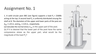
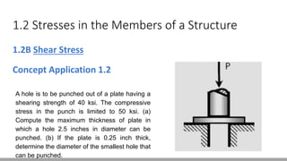
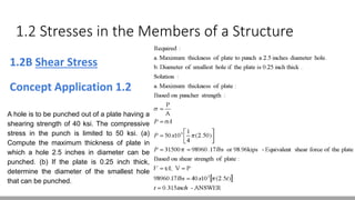
(a) Given: Shear strength = 40 ksi
Diameter of hole = 2.5 in
Compressive stress limit in punch = 50 ksi
Use the punching shear formula to find the maximum thickness:
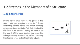
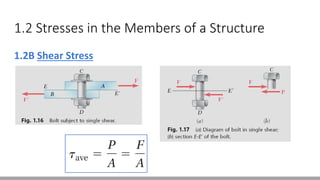
τ = P/A = 50 ksi
A = πDh/4
Solve for h:
h = 4P/(πDτ) = 4(50 ksi)/(π(2.5 in)(40 ksi)) = 0.625 in
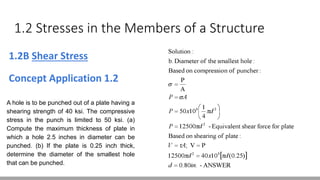
(b) Given: Thickness = 0.25 in
Shear strength = 40 ksi
Compressive stress limit = 50 ksi
Use the