Downloaded 12 times
![Review
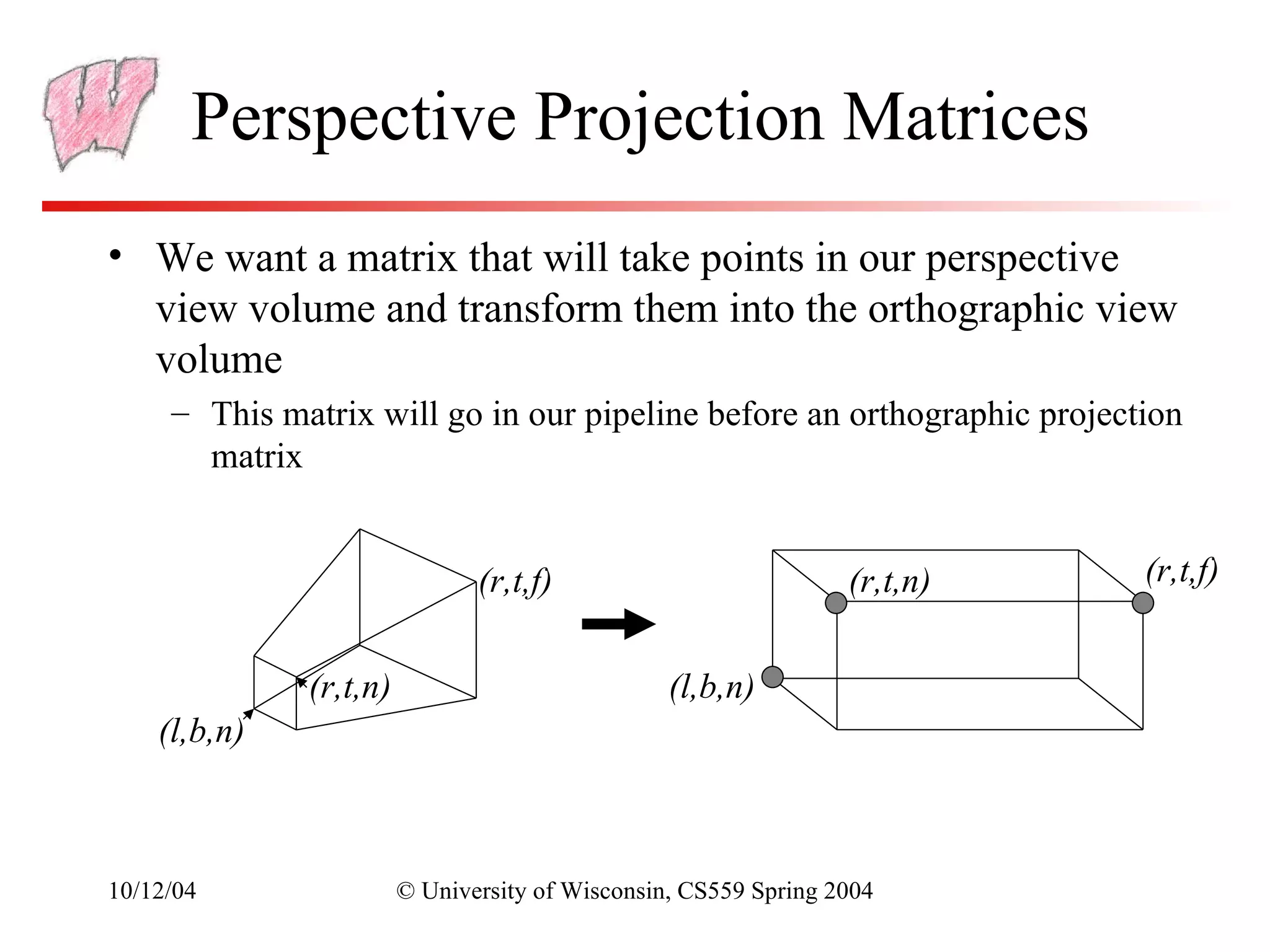
• View Space is a coordinate system with the viewer looking
down the –z axis, with x to the right and y up
• The World->View transformation takes points in world
space and converts them into points in view space
• The Projection matrix, or View->Canonical matrix, takes
points in view space and converts them into points in
Canonical View Space
– Canonical View Space is a coordinate system with the viewer
looking along –z, x to the right, y up, and everything to be drawn
inside the cube [-1,1]x[-1,1]x[-1,1] using parallel projection
10/12/04 © University of Wisconsin, CS559 Spring 2004](https://image.slidesharecdn.com/cs559-11-120411012333-phpapp02/75/Cs559-11-3-2048.jpg)
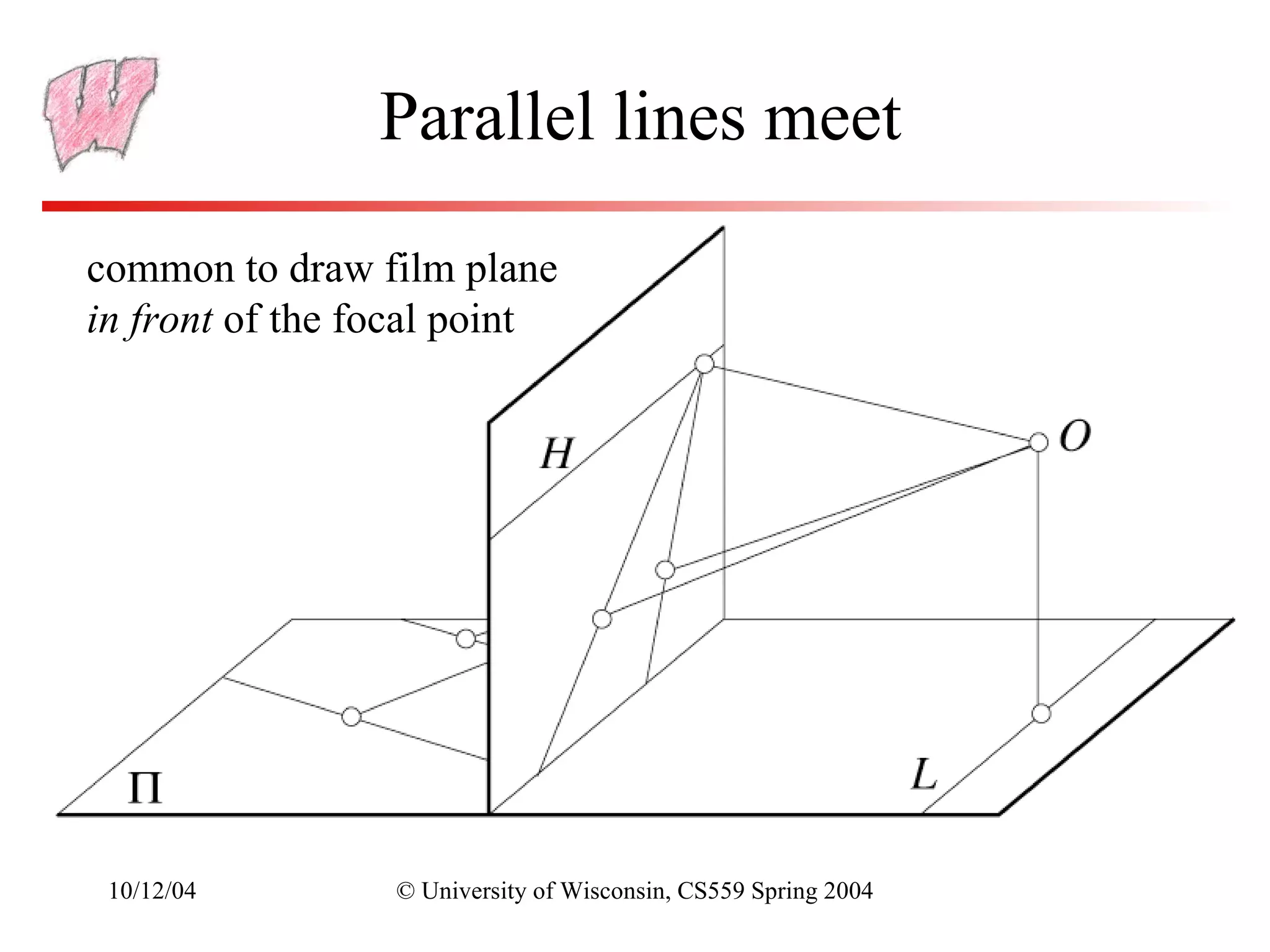
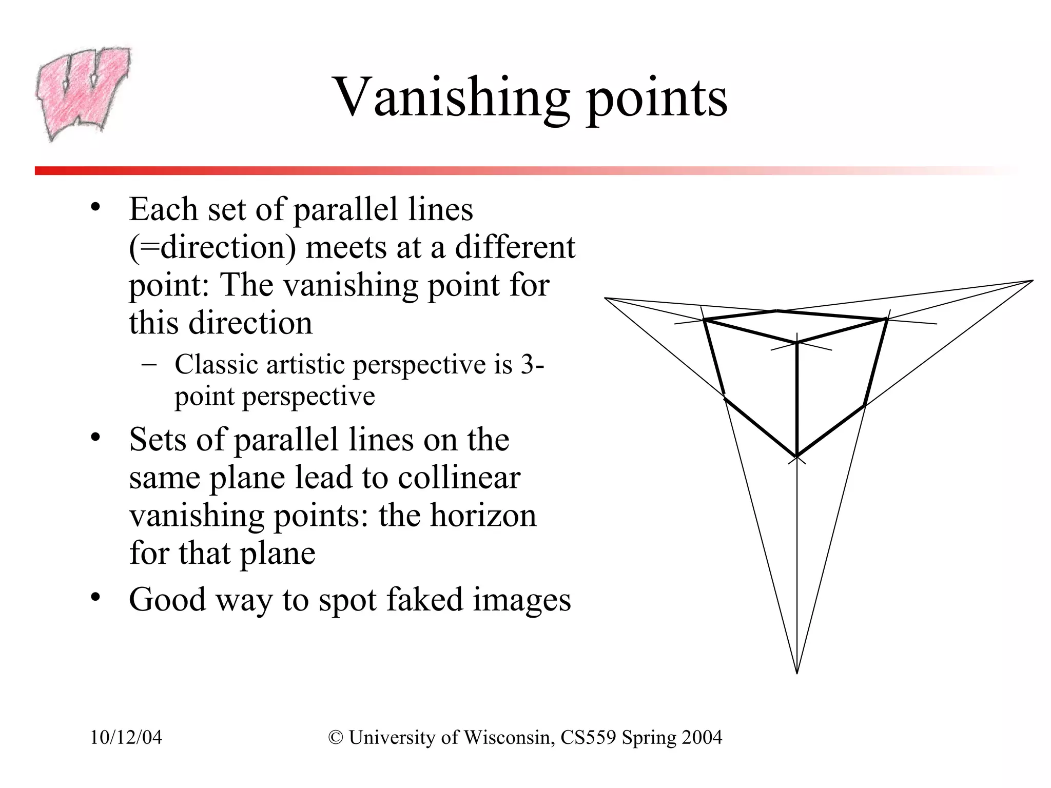
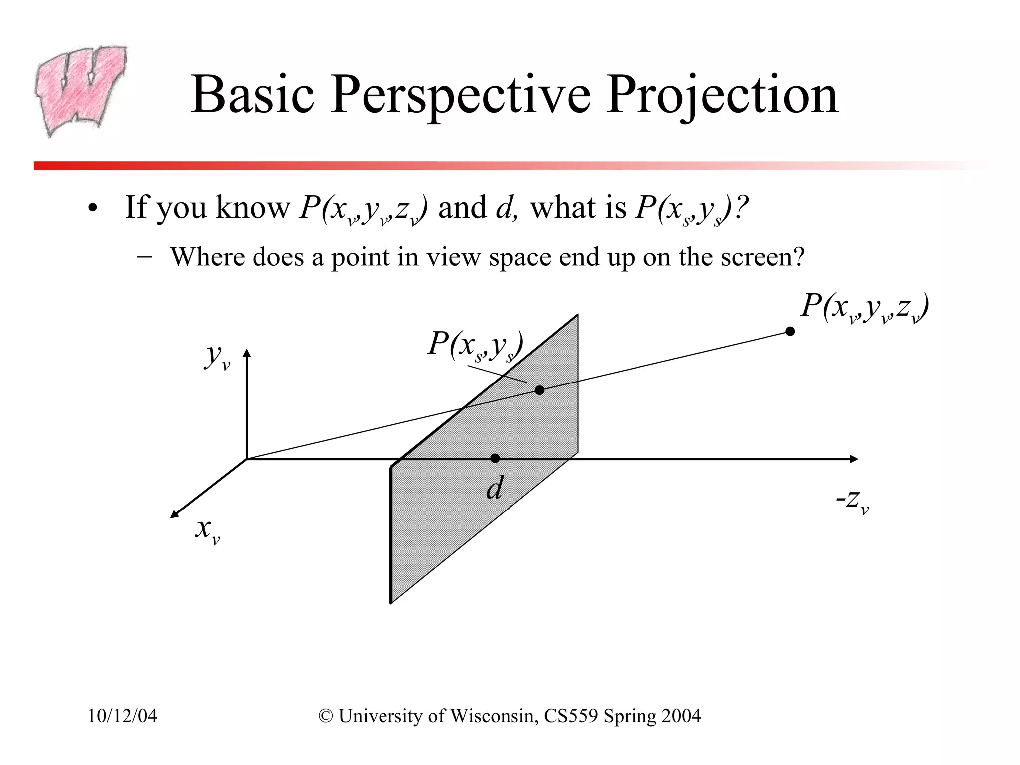


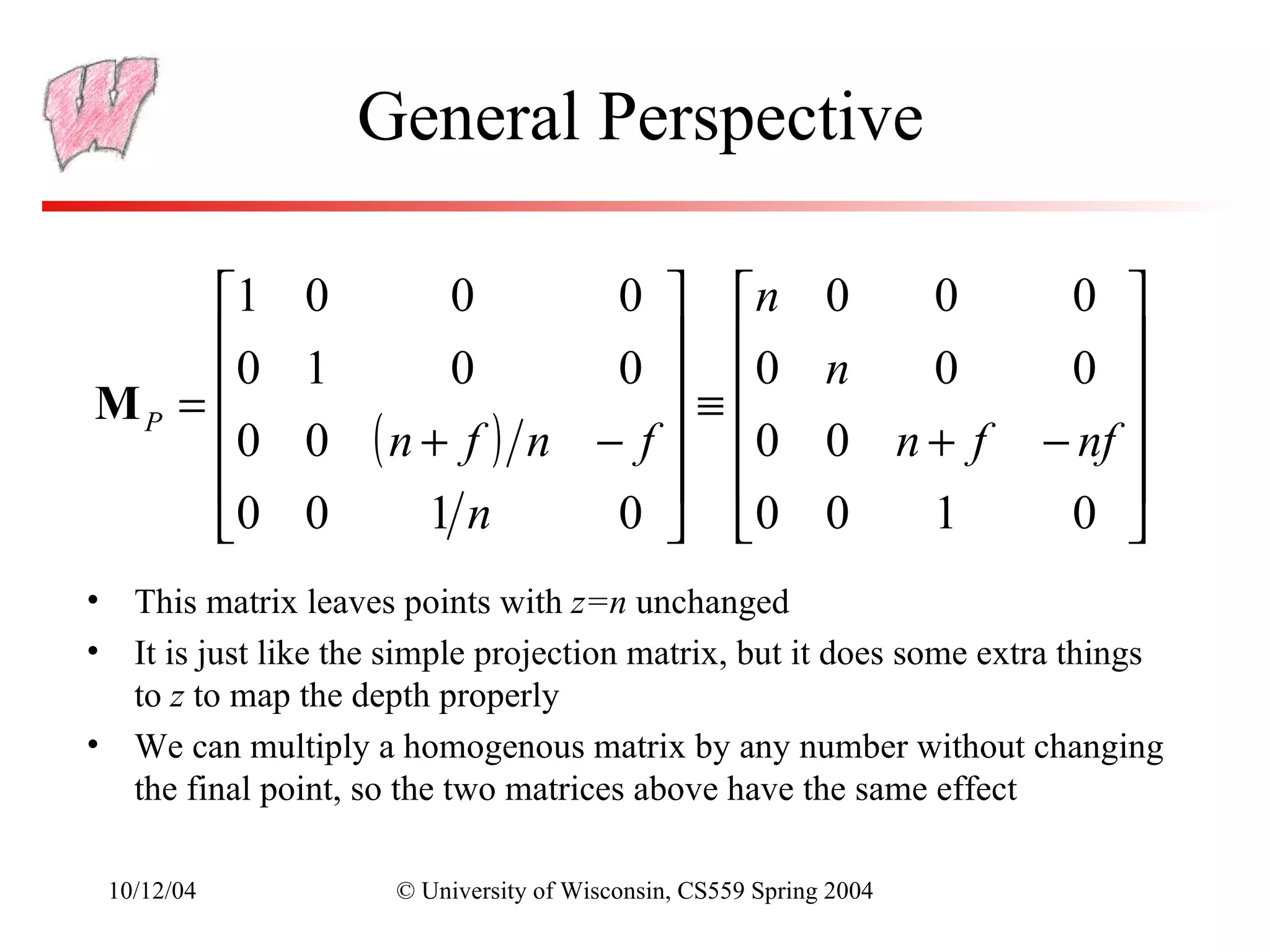
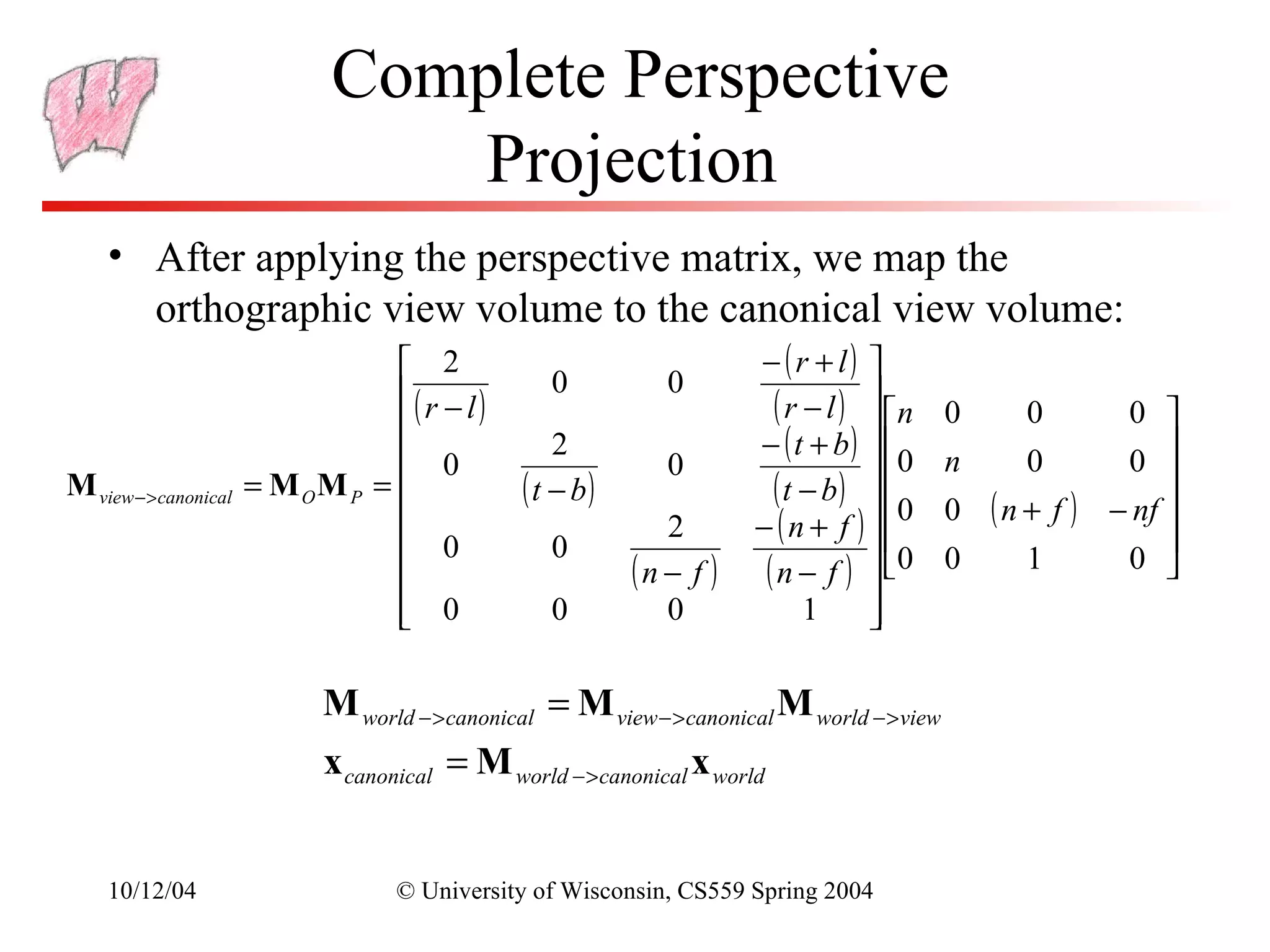


The document discusses perspective projection in computer graphics. It begins with an overview of orthographic projection and viewing transformations. It then covers perspective viewing, including the perspective viewing volume defined by clipping planes, field of view, and different parameters used to specify a camera such as focal distance and projection matrices. It also discusses how parallel lines appear to converge in perspective projections and how perspective is used in OpenGL.