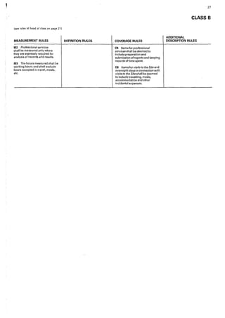
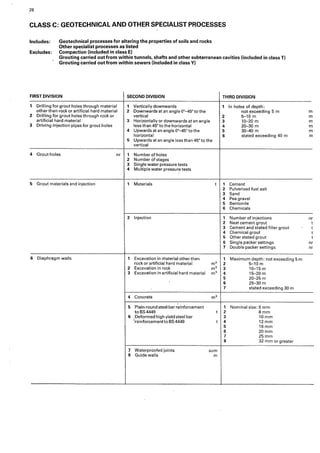
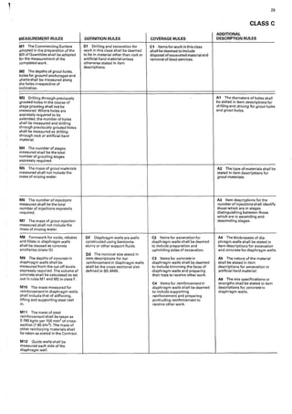
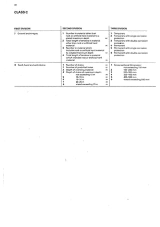
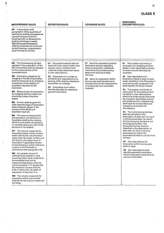
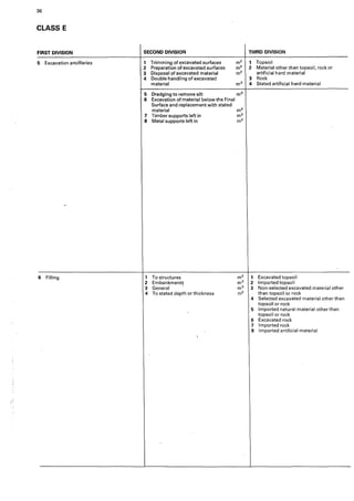
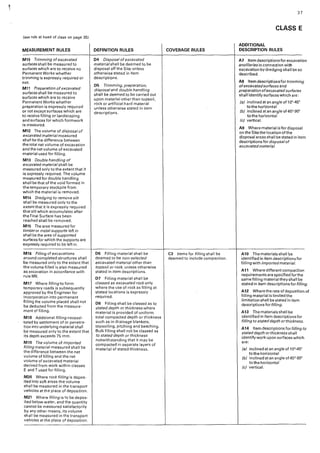
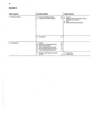
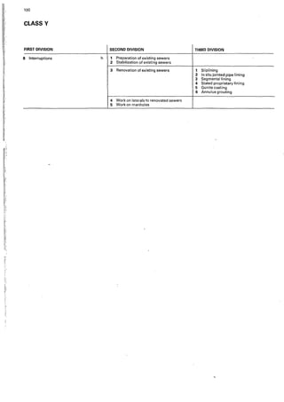
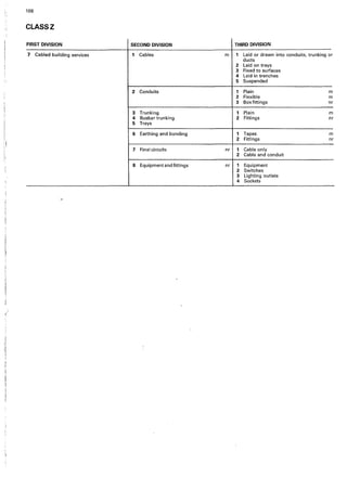
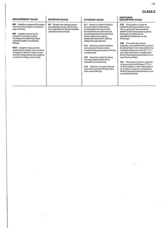
THE INSTITUTION OF CIVIL ENGINEERS
CESMM3
CIVIL ENGINEERING
STANDARD METHOD OF MEASUREMENT
THIRD EDITION
-
LI THOMAS TELFORD, LONDON, 1991
G3,*,* - Formwork
Wher~ the Specification "expressly requires" a stated finish the item should be measured under
08,2,*. Work required to achieve the finished surface after striking formwork, eg. Rubbing down
and making good, is included in 03,*,*and does not need to be billed separately under 08,2,*. A
Guidance Note on "Expressly required" was published in the May 1994 issue of Civil Engineering2
•
Class L - Pipework
L3-S,*,*-Rule Ml 1 - Measurement of Multiple Pipes
It has been suggested that in a multiple pipe run, the measurement could be interpreted as the length
along the centre lines multiplied by the number ofpipes. This is not the case and the intention is
that it should be the length ofthe bed, haunch or surround. As noted in the Handbook2
on page 137,
it should be remembered that Classes I, J, Kand L should always be considered as one composite
class. The problem is then resolved by referring to Class K Definition Rule D1 when reading Class ·
L Measurement Rule M11.
The Committee wishes to emphasize that its role is to provide advice on problems that arise
from the practical application of CESMM, but it does not exist to provide an arbitration service
and such problems must be dealt with under the mechanisms provided for in individual
contracts.
The last set of Guidance Notes for CESMM3 was published in Civil Engineering3 May 1994
and reproduced by permission in Civil Engineering Surveyor September 1994. Users and
readers were requested to comment on a proposal to extend CESMM to deal with the
measurement of maintenance work and/or renovation of existing structures. It would appear
there is little demand for this extension to be developed.
Comments and queries on CESMM should be referred in writing to: Mr. Drick Vernon,
Standing CESMMReview Committee, The Institution ofCivil Engineers, One Great George
Street, Westminster, LONDON SWJP 3AA.
References
I. Institution of Civil Engineers. Civil Engineering Standard Method ofMeasurement
(CESMM) in three editions. Thomas Telford Ltd., London 1976, 1985, 1991.
2. CESMM3 Handbook by Martin Barnes published by Thomas Telford Ltd., London 1992
3. Civil Engineering - The Proceedings ofthe Institution of Civil Engineers published·by
Thomas Telford Ltd., London May 1994 pages 48 and 49.
U:cesmmGuid04.not.doc 2
I
'
I__-
Published for the Institution of Civil Engineers by Thomas Telford Services Ltd,
1 Heron Quay, London E14 4JD
First edition 1976
Second edition 1985
Third edition 1991
Reprinted with corrections 1992, 1995
1¥PORTANT NOTE
Since CESMM3 was published in 1991, several errors have been identified and the
opportunity has been-taken to correct these errors in this reprint. For ease of reference the
changes between this second printing and the first printing are given below.
Page Reference Change
6 3.2 In lines 4 and 5 the words 'plain round mild steel
bar' have replaced 'mild steel bar'.
6 3.3 In line 3 the same change as above has been made.
11 5.18 The word 'CESMM3' has replaced 'the CESMM'.
17 Additional The term 'Certificate of Substantial Completion' has
Description been inserted in rule'A1'.
Rule A1
23 Additional The word 'and' has been inserted between 'pits' and
Description 'trenches' in place of the comma.
Rule A12
73 Measurement Anew rule'M11' has been inserted and the previous
Rule M11 rule'M11' has become rule'M12'.
76 Reference R6*5 The number '5' has been inserted in front of
'Transitions' in the Third Division.
77 Coverage Rule C4 The reference to rule 'M10' has replaced the
reference to rule 'M9'.
89 Additional A comma which previously appeared after 'masonry'
Description has been deleted.
Rule A2
103 Additional A bracket has been inserted after 'trusses' and a
Description bracket which appeared after 'joinery' has been
Rule A4 deleted.
107 Definition Rule D8 The word 'pipe' has been inserted in front of
'fittings'.
107 Note at foot of The note has been extended with the wording
page beginning 'provided that..:
© The Institution of Civil Engineers and The Federation of Civil Engineering Contractors, 1991
British Ubrary Cataloguing in Pub1"1cation Data
Civil engineering standard method of measurement.
-3,d ed.
1. Civil engineering-Measurement-Standards
I. Institution of Civil Engineers
624'.028'7 TA153
ISBN: 0 7277 1561 5
All rights, including translation, reserved. Except for fair copying, no part of this publication may be reproduced, stored in a
retrieval system, or transmitted in any fqrm or by any means electronic. mechanical, pho1ocopying, recording or otherwise,
without prior written permission being obtained from the publisher.
Whils1 every care has been taken in the preparation of this document neither the lnslitution nor the federation of Civil
Engineering Contractors nor any of their committees can accept any liability for any loss or damage which may be suffered by
any person or organisat~on as a result of Us use.
Printed and bound in Great Britain by William Clowes limited, Beccles and London
PREFACE
The Civil Engineering Standard Method of Measurement, third edition (CESMM3),
has been approved by the sponsors-the Institution of Civil Engineers and the
Federation of Civil Engineering Contractors-for use in works of civil engineering
construction. This third edition supersedes the second edition published in 1985.
Reference to CESMM3 in the Appendix to the Form of Tender, as provided for by
clause 57 of the ICE Conditions of Contract, sixth edition (January 1991 I is suffi-
cient to give effect to the use of this standard method of measurement for a
particular contract.
CESMM3 may be used with other conditions of contract such as the ICE Con-
ditions of Contract for Ground Investigation and the ICE Conditions of Contract
for Minor Works. When other conditions of contract are used, paragraph 1.2 and
clause numbers referred to in CESMM3 should be amended by a statemenf in the
Preamble in accordance with paragraph 5.4.
The Committee under whose guidance CESMM3 has been prepared will keep the
use of the document under review and consider any suggestions for amendment.
These should be addressed to The Secretary, The Institution of Civil Engineers,
1-7 Great George Street, London SW1P 3AA. Revision of the document will be
made when such action seems warranted.
CONTENTS
Foreword to the first edition
Foreword to the second edition
Foreword to the third edition
Section 1. Definitions
Section 2. General principles
Section 3. Application of the Work Classification
Section 4. Coding and numbering of items
Section 5. Preparation of the Bill of Quantities
Section 6. Completion, pricing and use of the Bill of Quantities
Section 7. Method-Related Charges
Section 8. Work Classification
Class A: General items, 16
Class B: Ground investigation, 20
Class C: Geotechnical and other specialist processes, 28
Class D: Demolition and site clearance, 32
Class E: Earthworks, 34
Class F: ln situ concrete, 40
Class G: Concrete ancillaries, 42
Class H: Precast concrete, 46
Class l: Pipework-pipes, 48
Class J: Pipework-fittings and valves, 50
Class K: Pipework-manholes and pipework ancillaries, 52
Class L: Pipework-supports and protection, ancillaries to laying and
excavation, 56
Class M: Structural metalwork, 60
Class N: Miscellaneous metalwork, 62
Class 0: Timber, 64
Class P: Piles, 66
Class 0: Piling ancillaries, ·70
Class R: Roads and pavings, 74
Class S: Rail track, 78
Class T: Tunnels, 82
Class U: Brickwork, blockwork and masonry, 88
Class V: Painting, 90
Class W: Waterproofing, 92
Class X: Miscellaneous work, 94
Class Y: Sewer and water main renovation and ancillary works, 96
Class Z: Simple building works incidental to civil engineering works, 102
2
3
4
5
6
8
9
13
14
15
FOREWORD TO THE FIRST EDITION
In 1964 the Council of the Institution of Civil Engineers set up a Committee under the
Chairmanship of T. A. L. (now Sir Angus) Paton, CMG, BSc(Eng), FICE, to propose
revisions to the Standwd Method of Measurement of Civil Engineering Quantities.
In 1971 the work of revision was undertaken by Martin Barnes, PhD, BSc(Eng), MICE,
who worked initially under an agreement with the University of Manchester Institute
of Science and Technology and, after he left the University in 1972, under a direct
agreement with the Institution of Civil Engineers. A Steering Committee was
appointed by the Council of the Institution of Civil Engineers to supervise the work.
The Steering Committee was enlarged in 1972 by the appointment of an additional
representative from each of the Institution of Civil Engineers, the Association of
Consulting Engineers and the Federation. of Civil Engineering Contractors. The
members of the committee(* indicates member appointed in 1971) were
*D. C. Goode, FICE, FIEAust, Chairman
*M. Agar, BSc, FICE, FIStructE, Institution of Civil Engineers
F. J. Cave, BSc, FICE, FRIGS, MTPI, FIMunE, FRSH, Institution of Civil Engineers
*H. R. Oakley, MSc(Eng), FICE, MIWE, FASCE, Association of Consulting
Engineers
P. B. Ahm, MSc, FICE, Association of Consulting Engineers
*R. B. Hill, BSc, FICE, FIStructE, Federation of Civil Engineering Contractors
J. A. Sneden, FRIGS, FIQS, Federation of Civil Engineering Contractors
J. B. B. Newton, BSc(Eng), FICE, co-opted
N. C. B. Brierley, BSc(Eng), FICE, co-opted
Late in 1972 a draft of the revised standard method of measurement was circulated
for comment to 71 representative bodies. Trial Bills of Quantities were prepared by
20 organizations. Discussions with interested bodies continued throughout 1973
and 1974 and the form of the present document owes much to the suggestions
made during this time by bodies outside the committee. The Steering Committee
is indebted to the many people who helped in this way.
The object.of the work has been to make improvements while retaining the good
features of the previous edition of the standard method of measurement. The
principal improvements sought are
(a) to standardize the layout and contents of Bills of Quantities prepared according
to the standard method of measurement
(b) to provide a systematic structure of bill items leading to more uniform
itemization and description
(c) to review the subdivision of work into items so that a more sensitive and
balanced description of the value of work in a contract is provided
(cl) to take account of new techniques in civil engineering construction and
management, their influence on the work itself and on the administration of
contracts.
A Bill of Quantities which in essence is no more than a price list of the Permanent
Works no longer adequately reflects the many variables in the cost of civil
engineering construction which have resulted from developments in constructional
techniques and methods. It has therefore been decided to provide for some
additional items of measured work and for other items, entered at the option of the
tenderer, directly related to methods of construction.
A system of work classification has been adopted as the basis of the method of
measurement so that Bills of Quantities can be compiled and used more easily, The
system should enable much of the repetitive clerical work associated with the use of
Bills of Quantities to be simplified, and make the use of computers easier.
The Work Classification incorporates a reference number for each type of work
component. These reference numbers may be used as a simple code for identifica-
tion of work. Their use as part of the item numbers in Bills of Quantities is
suggested, but is optional. The coding is sufficiently flexible not to inhibit
description of the particular work in each contract.
i
'I
! '
I:
i.
2
FOREWORD TO THE SECOND EDITION
In 1983 the Council of the Institution of Civil Engineers instructed the CESMM
Revil,W Committee to prepare a second edition of the Civil Engineering Standard
Method of Measurement. The members of the Review Committee were
H. R. Oakley, CBE, FEng, MSc(Eng), FICE, Chairman
D. C. Goode, CBE, FCGI, FICE
N. C. B. Brierley, BSc(Eng), FICE
N. M. L. Barnes, BSc(Eng), PhD, FICE, FCIOB, ACIArb, MBCS
The work of analysing the comments received on the first edition and of drafting the
second edition was undertaken by Martin Barnes and Partners who were assisted by
McGill and Partners.
Many organizations contributed comments and suggestions for amendment of
the document and others participated by reviewing drafts and giving
advice. The Review Committee is indebted to the many people who helped in this
way, and particularly to the Federation of Civil Engineering Contractors who
appointed a committee to review and comment upon the drafts.
The object of the amendments made in the second edition was twofold. Firstly it
was to take account of developments in civil engineering technology and in the
significance of different costs of civil engineering work which have taken place since
the first edition was published. Secondly it was to take the opportunity of altering
the wording of the small number of provisions of the first edition which experience
had shown were not working either as smoothly as they might or in the way which
had been intended. The second edition of the CESMM is consequently not a radical
departure from the first edition, but an update and general overhaul.
The two most noticeable changes are the categorization and upgrading of the
former notes in the work classification and the introduction of a standard method of
measurement for sewer renovation work. The rearrangement of the former notes
is intended to make the document easier to use in two ways. Firstly; the notes have
been re-named rules in order to emphasize that their provisions govern how work
should be described and measured in civil engineering bills of quantities and that
they have equal status with rules in any other part of the document. Secondly, they
have been divided in'to four categories to indicate the four separate functions which
they perform and have, as far as possible, been laid out alongside the parts of the
classification tables to which they relate.
The section for measurement of sewer renovation work has been introduced in
order to proviae for the considerably increased volume of work of this type now
being undertaken. The method of measurement for sewer renovation in this
document is based upon that devised originally for the Water Research Centre and
included in their standard specification. The Institution of Civil Engineers and the
Federation of Civil Engineering Contractors acknowledge the assistance given by
the wJter Research Centre in allowing this method of measurement to be embodied
in the CESMM.
3
FOREWORD TO THE THIRD EDITION
Although the second edition of the Civil Engineering Standard Method of
Measurement was published in 1985, a number of factors have combined to
cause the need for a third edition. The main changes incorporated in the third
edition (CESMM3) are amendments to enable its use with the ICE Conditions of
Contract, sixth edition (January 1991), and the introduction of a standard method
of measurement for water main renovation and for simple building works
incidental to civil engineering works (classes Y and Z). Account has also been
take of developments in civil engineering technology and the opportunity taken to
make minor amendments and corrections to the text of the second edition. There
are no changes in principle or in the general arrangement.
The Review Committee is indebted to a number of organizations and individuals
who have contributed comments and suggestions for amend(nent. The
committee is particularly indebted to E. C. Harris: Quantity Surveying whose
proposals formed the basis for the new class Z. The work of analysing the
comments and suggestions and drafting CESMM3 was undertaken by Coopers &
Lybrand Deloitte.
'The members of the Review Committee were
H. R. Oakley, CBE, FEng, MSc(Eng), FICE, Chairman
N. M. L. Barnes, FEng, BSc(Eng), PhD, FICE, FCIOB, ACIArb, MBCS, CBIM
Miss R. Beales, Barrister-at-Law
J. Banyard, MICE
H. A. Jones, MICE, Secretary
The committee is indebted to Dr Barnes of Coopers and Lybrand Deloitte for his
invaluable adyice and assistance throughout.
!
i:
i:
ll
i
4 r
SECTION 1. DEFINITIONS
1.1. In this document and in Bills of Quantities prepared according to the
procedure set forth herein the following words and expressions have the meanings
hereby assigned to them, except where the context otherwise requires.
1.2. 'Conditions of Contract' means the ICE Conditions of Contract, sixth edition
(January 1991 ), prepared by the Institution of Civil Engineers jointly with the
Association of Consulting Engineers and the Federation of Civil Engineering
Contractors.
1.3. Words and expressions defined in the Conditions of Contract have the same
meanings herein.
1.4. All references to clauses are references to clauses numbered in the Conditions
of Contract and references to paragraphs are references to paragraphs numbered
herein.
1.5. The word 'work' includes work to be carried out, goods, materials and services
to be supplied, and the liabilities, obligations and risks to be undertaken by the
Contractor under the Contract.
1.6. The expression 'expressly required' means shown on the Drawings, described
in the Specification or ordered by the Engineer pursuant to the Contract.
1.7. 'Bill of Quantities' means a list of items giving brief identifying descriptions
and estimated quantities of the work comprised in a Contract.
1.8. 'Daywork' means the method of valuing work on the basis of time spent by the
workmen, the materials used and the plant employed.
1.9. 'Work Classification' means the Work Classification set out in section 8.
1.10. 'Original Surface' means the surface of the ground before any work has been
carried out.
1.11. 'Final Surface" means the surface indicated on the Drawings to which
excavation is to be carried out.
1.12. 'Commencing Surface' means, in relation to an item in a Bill of Quantities, the
surface of the ground before any work covered by the item has been carried out.
'Commencing Surface' means, in relation to a group of items in a Bill of Quantities
for work in different materials in an excavation or a bored, drilled or driven hole, the
surface of the ground before any work covered by any item in the group has been
carried out.
,
1.13. 'Excavated Surface' means, in relation to an item in a Bill of Quantities, th·e
surface to which excavation included in the work covered by the item is to be carried
out. 'Excavated Surface' means, in relation to a group of items in a Bill of Quantities
for excavation in different materials, the surface to which excavation included in the
work covered by any item in the group is to be carried out.
1.14. A hyphen between two dimensions means a range of dimensions which
includes all dimensions exceeding that preceding the hyphen but not exceeding that
following the hyphen.
1.15. 'BS' means British Standard. References to British Standards are deemed
to include equivalent national standards of member states of the European
Community and European Community standards.
i
5
SECTION 2. GENERAL PRINCIPLES
Title application and extent
Object of CESMM3
Objects of the Bill of Quantities
2.1. The title of this document is the Civil Engineering Standard Method of
Measurement, third edition, which is abbreviated to CESMM3. CESMM3 is
intended to be used in conjunction with the Conditions of Contract and only in
connection with civil engineering works and simple building works incidental to
civil engineering works.
2.2. CESMM3 provides for simple building works incidental to civil
engineering works to be measured in accordance with class Z. CESMM3 does
not deal with the preparation of Bills of Quantities for complex mechanical or
electrical engineering work, or complex building work or work which is seldom
encountered in civil engineering contracts. Where any such work is to be included
in a Contract for civil engineering work, it shall be itemized and described in the
Bill of Quantities in sufficient detail to enable tenderers to price it adequately and.
the method of measurement shall be stated in the Preamble to the Bill of
Quantities in accordance with paragraph 5.4.
2.3. The object of CESMM3 is to set forth the procedure according to which the
Bill of Quantities shall be prepared and priced and the quantities of work
expressed and measured.
2.4. The objects of the Bill of Quantities are
(a) to provide such information of the quantities of work as to enable tenders to be
prepared efficiently and accurately
(b) when a Contract has been entered into, to provide for use of the priced Bill of
Quantities in the valuation of work executed.
2.5. In order to attain these objects, work should be itemized in the Bill of
Quantities in sufficient detail for it to be possible to distinguish between the different
classes of work, and between work of the same nature carried ,out in different
locations or in any other circumstances which may give rise to different considera-
tions of cost. Consistent with these requirements the layout and content of the Bill
of Quantities should be as simple and brief as possible.
2.6. All work which is expressly required should be covered in the Bill of
Quantities.
· 2.7. CESMM3 seeks to attain these objects principally by the use of the Work
Classification. This defines
(a) how work is to be divided into separate items in the Bill of Quantities
(b) the information to be given in item descriptions
(c) the units in which the quantities against each item are to be expressed
(d) how the work is to be measured for the purpose of calculating quantities.
I
6
SECTION 3. APPLICATION OF THE WORK CLASSIFICATION
Item descriptions
Mode of description
Separate items
Units of measureQtent
Measurement rules
Definition rules
Coverage rules
3.1. The Work Classification divides work commonly encountered in civil engi-
neering contracts into 26 main classes. Each class comprises up to three divisions
which classify work at successive levels of detail. Each division comprises a list of
up to eight descriptive features of work. Each item description in the Bill of
Quantities shall identify the component of work covered with respect to one
feature from each division of the relevant class, e.g.
Class H (precast concrete) contains three divisions of classification. The first
classifies different types of precast concrete units, the second classifies different
units by their dimensions, and the third classifies them by their mass. Each
item description for precast concrete units shall therefore identify the compo-
nent of work in terms of the type of unit, its dimensions and mass.
3.2. To avoid unnecessary length, item descriptions for Permanent Works shall
generally identify the component of the Works and not the tasks to be carried out
by the Contractor, e.g.
An item should be described as 'Plain round mild steel bar reinforcement to BS 4449
nominal size 20·mm', not as 'Supply, deliver, cut, bend and fix plain round mild
steel bar reinforcement to BS 4449 nominal size 20 mm'.
3.3. Where the work identified by an item is specifically limited, the limitation
shall be stated in the item description, e.g.
'Plain round mild steel bar reinforcement to BS 4449 nominal· size 20 mm
excluding supply and delivery to the Site.'
Item descriptions for work which is divided between two classes require such
limitations to be stated, e.g.
Item descriptions for miscellaneous metalwork inserts which are to be cast into
concrete require appropriate additional description if items are given in both
class G for casting in the inserts and class N for supplying the inserts.
3.4. The work shall be divided into items in the Bill of Quantities so that the
component of work which is included in each item does not exhibit more than one
feature from each div.ision of any one class of the Work Classification, e.g.
One item for precast concrete work shall not include more than one of the types of
concrete unit listed in the first division of class H, neither shall it include
different units whose dimensions are not within one of the classifications listed
in the second division of class H, nor shall it include different units whose mass
does not lie within one of the ranges listed in the third division of class H.
· 3.5. The unit of measurement for each item shall be that stated for the item in the
Work Classification. The unit of measurement stated against a descriptive feature
in the Work Classification shall apply to all items to which that descriptive feature
applies. "
3.6. Measurement rules in the Work Classification set out the conditions under
which work shall be measured and the method by which the quantities shall be
computed if other than in accordance with paragraph 5.18.
3.7. Definition rules in the Work Classification define the extent and limits of the
class of work represented by a word or expression used in the Work
Classification and in a Bill of Quantities prepared in accordance with CESMM3.
3.8. Coverage rules in the Work Classification provide that the work stated ·is
deemed to be included in the appropriate items to the extent that such work is
included in"the Contract. A coverage rule does not state all the work covered by an
Additional description rules
Applicability of rules
7
item and does not preclude any of the work stated being covered by a Method-
Related Charge.
3.9. Description of an item in addition to that required in accordance with
paragraph 3.1 shall be given where required by any provision of section 5 or by any
applicable additional description rule in the Work Classification. Where additional
description is given, a separate item shall be given for each component of work
exhibiting a different additional feature, e.g.
Additional description rule 4,1 of class H requires that the specification of the
concrete in each precast concrete unit shall be stated. Accordingly, this rule also
means that separate items shall be· given for units cast from concrete of
different specifications.
3.10. Where a descriptive feature in the Work Classification identifies a range or
group of dimensions and an applicable additional description rule requires the
particular dimension to be stated, the range or group of dimensions shall not also be
stated, e.g.
Additional description rule A2 of class I requires that the nominal bores of pipes
shall be stated in item descriptions. The range of nominal bore taken from the
second division of the classification of class I shall not also be stated.
3.11. Rules printed on a right-hand page above a double line apply to all work in
the class. Other rules on a right-hand page apply to particular groups of items as
shown by the classification table.
8
SECTION 4. CODING AND NUMBERING OF ITEMS
Coding 4.1. For convenience of reference each item in the Work Classification has been
assigned a code number consisting of a letter and not more than three digits. The
letter corresponds to the class in the Work Classification in which the item occurs
and the digits give the position of the item in the first, second and third divisions of
the class, e.g.
Item numbers
Coding of unclassified items
Numbering of items with
additional description
Code H 1 3 6 identifies an item as
class H
first division 1
second division 3
third division 6
µrecast concrete
beams
length 7-10 m
mass 5-101
4.2. The symbol • is used in the rules to the Work Classification to indicate all
numbers in the appropriate division, e.g.
H 1 3 • means the group of code numbers.from H 1 3 1 to H 1 3 8 inclusive.
4.3. Code numbers may be used to number the items in the Bill of Quantities, the
items within the Bill of Quantities being listed in order of ascending code number.
4.4. Code numbers used as item numbers in the Bill of Quantities shall not form
part of the item descriptions or be taken into account in the interpretation of the
Contract.
4.5. Where a feature of an item is not listed in the Work Classification the digit
9 shall be used in the appropriate positions in the code number.
4.6. Where there is an item to which a division of classification does not apply or
for which fewer than three divisions of classification are given the digit O shall be
used in the appropriate positions in the code number.
4.7. Additional description given for an item in accordance with paragraph 3.9 is
not represented by the code number. Where code numbers are used as item
numbers a_suffix number shall be used to distinguish items which have the same
code number but different additional description, e.g.
Additional description rule A1 of class H requires that additional description be
given for precast concrete units stating their position in the Works and the
specification of the concrete used. If three items are required within one part
of the Bill of Quantities to allow for precast concrete beams having the same
code but different additional description, the items should be numbered
H136.1
H136.2
H136.3
9
SECTION 5. PREPARATION OF THE BILL OF QUANTITIES
Measurement of completed work
Sections of the Bill of Quantities
List of principal quantities
Preamble
Daywork Schedule
5.1. Appropriate provisions of this section shall also apply to the measurement of
completed work.
5.2. The Bill of Quantities shall be divided into the following sections.
(a) List of principal quantities
(bl Preamble
(cl Daywork Schedule
(a') Work items (grouped into parts)
(el Grand Summary.
5.3. A list of the principal componenis of the Works with their approximate
estimated quantities shall be given solely to assist tenderers in making a rapid
assessment of the general scale and character of the proposed Works prior to the
examination of the remainder of the Bill of Quantities and the other contractual
documents on which their tenders will be based.
5.4. The Preamble shall state the methods of measurement other than CESMM3,
if any, which have been adopted in the preparation of the Bill of Quantities and
are to be used for the measurement of any part of the Works. Such methods of
measurement shall comprise those adopted and to be used for any work not
covered by CESMM3 and any amendments to CESMM3 which have been
adopted and are to be used. Amendments comprising abbreviation of CESMM3
are usually necessary for Contractor~designed work and work which is intended
to involve selection between alternatives at the discretion of the Contractor. The
extent of the work affected by all amendments to CESMM3 shall be stated in the
Preamble.
5.5. Where excavation, boring or driving is included in the work a definition of rock
shall be given in the Preamble and this definition shall be used for the purposes of
measurement.
5.6. The Daywork Schedule, if any, shall comprise either
(a) a list of the various classes of labour, materials and plant for which Daywork
rates or prices are to be inserted by the tenderer together with a statement of
the conditions under which the Contractor shall be paid for work executed on a
Daywork basis, or
(bl a statement that the Contractor shall be paid for work executed on a Daywork
basis at rates and prices calculated by adding the percentage additions stated
in the Schedules of Dayworks carried out incidental to Contract Work issued by
the Federation of Civil Engineering Contractors to the rates and prices
contained in the aforementioned Schedules and by making further adjustments
as follows,
Schedule 1: Labour
Schedule 2: Materials
Schedule 3: Plant
Schedule 4: Supplementary chargest
addition/deduction-!(• of- tper cent
addition/deduction* of- tper cent
*Appropriate deletion to be made by the Contractor when tendering
tPercentage to be inserted by the Contractor when tendering
tSupplementary charges shall not include the charges referred to in notes and
conditions 21ii), 3 and 6 of schedule 4
Payments shall be made under the conditions and using the rates and prices
contained in the edition of the aforementioned Schedules current at the date of
execution of the Daywork.
,.
i!,
L
10
Work items
Division of the Bill of Quantities
into parts
Headings and sub-headings
Extent of itemization and
description
Descriptions
Ranges of dimensions
Prime Cost Items
5.7. Provisional Sums for work executed on a Daywork basis may be given
comprising separate items for labour, materials, plant and supplementary
charges. Where a Oaywork Schedule of the form stated in sub-paragraph (b) of
paragraph 5.6 is used each Provisional Sum shall be followed by an item for the
adjustment referred to in that sub-paragraph. The price inserted against each
such item shall be calculated by applying the percentage addition or deduction
inserted by the Contractor in the Daywork Schedule to the amount of the
associated Provisional Sum.
5.8. The items in the Bill of Quantities which are-to be priced and to contribute to
the Tender Total may be arranged into numbered parts to distinguish between those
parts of the work of which the nature, location, access, limitation on sequence or
timing or any other special characteristic is thought likely to give rise to different
methods of construction or considerations of cost. General items (class A) may be
grouped as a separate part of the Bill of Quantities. Items in each part shall be
arranged in the general order of the Work Classification.
5.9. Each part of the Bill of Quantities shall be given a heading and groups of
items within each part be given sub-headings, Headings and sub-headings shall
be read as part of the item descriptions to which they apply. A line shall be
drawn across the item description column below the last item to which each
heading or sub-heading applies. Headings and sub-headings shall be repeated at
the start of each new page which lists items to which they apply.
5.10. All work shall be itemized and the items shall be described in accordance with
the Work Classification, but further itemization and additional description may be
provided if the nature, location, importance or any other special characteristic of the
work is thought likely to give rise to special methods of construction or considera-
tions of cost.
5.11. Descriptions shall identify the work covered by the respective items, but the
exact nature and extent of the work is to be ascertained from the Drawings,
Specification and Conditions of Contract, as the case may be, read in conjunction
with the Work Classification.
5.12. Any detail of description required to be given in accordance with the Work
Classification may be omitted from an item description provided that a reference is
given in its place which identifies precisely where the omitted information may be
found on a drawing or i~ the Specification.
5.13. Where an item description compiled in accordance with the Work Classifica-
tion would be insufficient to·identify clearly the particular work covered by the item
additional description shall be given to identify the work by reference to its location
or other .physical features shown on the Drawings or described in the Specification.
5.14. Where all the components of work included in an item are of one dimension
within a range given in the Work Classification that dimension may be stated in the
item description in place of the range of dimensions given.
5.15. The estimated price of work to be carried out by a Nominated Sub-contractor
shall be given in the Bill of Quantities as a Prime Cost Item. Each Prime Cost Item
shall be followed by
(a) an item for a sum for labours in connection therewith which, in the absence of
any express provision in the Contract to the contrary, shall include only
(i) in any case in which the Nominated Sub-contractor is to carry out work
Provisional Sums
Quantities
Units of measurement
Work affected by water
Ground and excavation levels
11
on the Site for allowing him to use temporary roads, scaffolding, hoists,
messrooms, sanitary accommodation and welfare facilities which are provided
by the Contractor for his own use and for providing space for office accommo-
dation and storage of plant and materials, for disposing of rubbish and for
providing light and water for the work of the Nominated Sub-contractor, and
(ii) in any case in which the Nominated Sub-contractor is not to carry out work
on the Site for unloading, storing and hoisting materials supplied by him and
returning packing materials, and
(b) an item expressed as a percentage of the price of the Prime Cost Item in respect
of alt other charges and profit.
5.16. Where any goods, materials or services supplied by a Nominated Sub-
contractor are to be used by the Contractor in connection with any item, reference
shall be made in the description of that item, or in the appropriate heading or sub-
heading, to the Prime Cost Item under which the goods or materials or services are
to be supplied.
5.17. Provision for contingencies shall be made by giving Provisional Sums in the
Bill of Quantities and not by increasing the quantities beyond those of the work
expected to be required. Provisional Sums for specific contingencies shall be given
in the general items of the Bill of Quantities. A Provisional Sum for a general
contingency allowance, if required, shall be given in the Grand Summary in
accordance with paragraph 5.25.
5.18. The quantities shall be computed net using dimensions from the Drawings,
unless directed otherwise by a measurement rule in CESMM3 or by the
Contract, and no allowance shall be made for bulking, shrinkage or waste.
Quantities may be rounded up or down where appropriate. Fractional quantities
are not generally necessary and should not be given to more than one place of
decimals.
5.19. The following units of measurement and abbreviations shall be used.
Unit Abbreviation
Millimetre mm
Metre m
Square millimetre mm2
or mm2
Square metre m2
or m2
Hectare ha
Cubic metre m3
or m3
Kilogramme kg
Tonne
Sum sum
Number nr
Hour h
Week wk
5.20. Where an existing body of open water (other than groundwater) such as a
river, stream, canal, lake or body of tidal water is either on the Site or bounds the
Site, each body of water shall be identified in the Preamble to the Bill of
Quantities. A reference shall also be given to a drawing indicating the boundaries
and surface level of each body of water or, where the boundaries and surface leyels
fluctuate, their anticipated ranges of fluctuation.
5.21. The Commencing Surface shall be identified in the description of each item
for work involving excavation, boring or driving for which the Commencing Surface
is not the Original Surface. The Excavated Surface shall be identified in the
12
Form and setting
Grand Summary
General Contingencv Allowance
Adjustment Item
Total of the Priced Bill of Quantities
description of each item for work involving excavation for which the Excavated
Surface is not the Final Surface. The depths of excavation stated in accordance with
the Work Classification shall be measured from the Commencing Surface to the
Excavated Surface.
5.22. The Bill of Quantities should be set out on paper of A4 size. The work items
should be set out within columns headed and ruled consecutively as follows.
Column heading Column width
Number 20 mm
Item description 90 mm
Unit 10 mm
Quantity 20 mm
Rate 20mm
Amount:£ 20 mm
p .8mm
5.23. Provision shall be made for the amounts inserted on each page to be totalled
and carried to a summary of each part of the Bill of Quantities and for the total of
each Part Summary to be carried to the Grand Summary.
5.24. The Grand Summary shall contain a tabulation of the parts of the Bill of
Quantities with provision for insertion of the total of the amounts brought forward
from the Part Summaries.
5.25. A Provisional Sum for a general contingency (thl'l General Contingency
Allowance), if required, shall be given in the Grand Summary following the total of
the amounts brought forward from the Part Summaries.
5.26. An item described as the Adjustment Item shall be given in the Grand
Summary following the total of the amounts brought forward from the Part
Summaries and the General Contingency Allowance, if any (see paragraphs 6.3,
6.4 and 6.5).
5.27. Provision shalt be made for insertion of the total of the amounts brought
forward from the Part Summaries, the amount of the General Contingency
Allowance, if any, and the amount of the Adjustment Item.
13
SECTION 6. . COMPLETION, PRICING AND USE OF THE BILL OF QUANTITIES
Insertion of rates and prices
Parts to be totalled
Adjustment Item
6.1. Rates and prices shall be inserted in the rate column of the Bill of Quantities in
pounds sterling with pence inserted as decimal fractions of one pound.
6.2. Each part of the Bill of Quantities shall be totalled and the totals carried to the
Grand Summary.
6.3. A tenderer may insert a lump sum addition or deduction against the
Adjustment Item given in the Grand Summary in adjustment of the total of the
priced Bill of Quantities.
6.4. For the purposes of clause 60 interjm additions or deductions on account of
the amount, if any, of the Adjustment Item shall be made by instalments in
interim certificates in the proportion that the amount referred to in clause 60(2)(a)
bears to the total of the priced Bill of Quantities before the addition or deduction
of the amount of the Adjustment Item and a statement to this effect shall appear
in the Preamble to the Bill of Quantities. Such interim additions or deductions
shall be made before deduction of the retention moneys, and shall not exceed in
the aggregate the amount of the Adjustment Item. If by the date of issue
pursuant to clause 48 of the Certificate of Substantial Completion for the whole of
the Works any balance of the amount of the Adjustment Item is outstanding it
shall be added to or deducted from the moneys then due.
6.5. In determining the Effective Value for the purposes of the Contract Price
Fluctuations clause, if applicable, account shall be taken of any addition to or
deduction from the amounts due to the Contractor under clause 60 in respect of the
Adjustment Item.
14
SECTION 7. METHOD-RELATED CHARGES
Definitions 7.1. For the purposes of this section the following words and expressions shall
have the meanings hereby assigned to them.
Insertion by a tenderer
Itemization
Description
Contractor not bound to adopt
method
Charges not to be measured
Payment
Payment when method not
adopted
(a) 'Method-Related Charge' means the sum for an item inserted in the Bill of
Quantities by a tenderer in accordance with paragraph 7.2.
(b) 'Time-Related Charge' means a Method-Related Charge for work the cost of
which is to be considered as proportional to the length of time taken to execute
the work.
(c) 'Fixed Charge' means a Method-Related Charge which is not a Time-Related
Charge.
7.2. A tenderer may insert in the Bill of Quantities such items for Method-Related
Charges as he may decide to cover items of work relating to his intended method of
executing the Works, the costs of which are not to be considered as proportional to
the quantities of the other items and for which he has not allowed in the rates and
prices for the other items.
7.3. Where possible the itemization of Method-Related Charges should follow the
order of classification and the other requirements set out in class A of the Work
Classification, distinguishing between Time-Related Charges and Fixed Charges.
Method-Related Charges may be inserted to cover items of work other than those
set out in class A.
7.4. Each item for a Method-Related Char~e inserted in the Bill of Quantities shall
be fully described so as to define precisely! the extent of the work covered and to
identify the resour_ces to be used and the rjarticular itefns of Permanent Works or
Temporary Works, if any, to which the iterlj relates.
7.5. The insertion by the Contractor of an item for a Method-Related Charge in the
Bill of Qu~ntities when tendering shall not bind him to adopt the method stated in
the item description in executing the Works.
7.6. Method-Related Charges shall not be subject to admeasurement but shall be
deemed to 'be prices for the purposes of clauses 52(1 ), 52(2) and 56(2).
7.7. Method-Related Charges shall be certified and paid pursuant to clauses
60(1)(d) and 60(2)(a) and a statement to this effect shall appear in the Preamble to
the Bill of Quantities.
7.8. In the event of the satisfactory execution of any part of the Works which has
been the subject of an item for a Method-Related Charge using, whether in whole
or in part, a method other than that described in the item the Contractor shall
nevertheless be entitled to· payment of the Method-Related Charge or the balance
thereof, as the case may be, by such instalments at such times and upon such
events1 as may from time to time be agreed between the Engineer and the
Contractor. In default of such agreement the Method-Related Charge, or the
balance then unpaid, shall be treated as if it were an addition to the Adjustment
Item referred to in paragraphs 6.3, 6.4 and 6.5 and allowed to the Contractor by
way of instalments in interim certificates accordingly. The amount of a Method-
Related Charge shall be neither increased nor decreased by reason only of any
change in method made by the Contractor, unless such change has been ordered
by the Engineer, in which case the provisions of clause 52 shall apply.
SECTION 8. WORK CLASSIFICATION
Class A: General items, 16
Class B: Ground investigation, 20
Class C: Geotechnical and other specialist processes, 28
Class D: Demolition and site clearance, 32
Class E: Earthworks, 34
Class F: In situ concrete, 40
Class G: Concrete ancillaries, 42
Class H: Precast concrete, 46
Class I: Pipework-pipes, 48
Class J: Pipework-fittings and valves, 50
Class K: Pipework-manholes and pipework ancillaries, 52
Class L: Pipework-supports and protection, ancillaries to laying and excavation, 56
Class M: Structural metalwork, 60
Class N: Miscellaneous metalwork, 62
Class 0: Timber, 64
Class P: Piles, 66
Class Q: Piling ancillaries, 70
Class R: Roads and pavings, 74
Class S: Rail track, 78
Class T: Tunnels, 82
Class U: Brickwork, blockwork and masonry, 88
Class V: Painting, 90
Class W: Waterproofing, 92
Class X: Miscellaneous work, 94
Class Y: Sewer and water main renovation and ancillary works, 96
Class Z: Simple building works incidental to civil engineering works, 102
15
16
CLASS A: GENERAL ITEMS
Includes: General obligations, site sertices and facilities, Temporary Works, testing of materials and work, Provisional
Sums and Prime Cost Items
Items to cover .elements of the cost of the work which are not to be considered as proportional to the
quantities of tile Permanent Works
FIRST DIVISION SECOND DIVISION THIRD DIVISION
1 Contractual requirements 1 Performance bond
2 Insurance of the Works
3 Third party insurance
2 Specified requirements , Accommodation for the Engineer's staff 1 Offices
2 Laboratories
3 Cabins
2 Services for the Engineer's staff t Transport vehicles
2 Telephones
3 Equipment for use by the Engineer's staff 1 Office equipment
2 Laboratory equipment
3 Surveying equipment
4 Attendance upon the Engineer's staff 1 Drivers
2 Chainmen
3 Laboratory assistants
-
5 Testing of materials
6 Testing of the Works
7 Temporary Works 1 Traffic diversions
2 Traffic regulation
3 Access roads
4 Bridges
5 Cofferdams
6 Pumping
7 De-watering
8 Compressed air for tunnelling
3 Method-Related Charges 1 Accommodation and buildings 1 Offices
2 Laboratories
3 Cabins
4 Stores
5 Canteens and messrooms
2 Services 1 Electricity
2 Water
3 Security
4 Hoardings
5 Site transport
6 Personnel transport
 7 Welfare
3 Plant 1 Cranes
2 Transport
3 Earthmoving
4 Compaction
5 Concrete mixing
6 Concrete transport
7 Pile driving
8 Pile boring
4 Plant 1 Pipelaying
2 Paving
3 Tunnelling
4 Crushing and screening
(continued)
5 Boring and drilling
MEASUREMENT RULES
M1 The unit of measurement for
general items shall be the sum,
except where another unit of
measurement is used in
accordance with rule M2.
M2 A quantity shall be given
against all items for specified
requirements of which the value
is to be ascertained and
determined by admeasurement in
accordance with clause 56(1 ). A
unit of measurement shall be
stated for each such item.
M3 Items shall be given in this
class for all testing for which
items are not given separately as
set out in other classes.
M4 Items for Method-Related
Charges, if any, shall be inserted
by the tenderer in accordance
with section 7.
NOTE
DEFINITION RULES
01 All work other than the
Permanent Works which is
expressly stated in the Contract to
be carried out by the Contractor
and of which the nature and
extent is expressly stated in the
Contract sha11 be classed as
specified requirements.
COVERAGE RULES
C1 Items for insurance classed
as contractual requirements shall
be deemed to include only
provision of insurance in
accordance with clause!, 21 and
23 unless otherwise stated.
17
CLASS A
ADDITIONAL
DESCRIPTION RULES
A1 Item descriptions for work
classed as specified
requirements which is to be
carried out afterthe issue ofthe
Certificate of SubstantiaI
Completion shall so state.
AZ Item descriptions for work
classed as specified requirements
shall distinguish between the
establishment and removal of
services or facilities and their
continuing operation or
maintenance.
A3 Item descriptions for testing
ofmaterials and testing ofthe
Works shall include particulars of
samples and of methods of
testing.
A4 Item descriptions for
Method-Related Charges shall
distinguish between Fixed and
Time-Related Charges.
Method-Related Charges may be inserted by the tenderer in accordance with paragraph 7.2 for insurances additional to those classed as contractual
requirements.
18
CLASS A
FIRST DIVISION SECOND DIVISION THIRD DIVISION
3 Method-Related Charges (continued) 5 Tern porary Works 1 Traffic diversions
2 Traffic regulation
3 Access roads
4 Bridges
5 Cofferdams
6 Pumping
7 De-watering
8 Compressed air for tunnelling
6 Temporary Works 1 Access scaffolding
2 Support scaffolding and propping
3 Piling .
4 Formwork
5 Shafts and pits
6 Hardstandings
7 Supervision and labour 1 Supervision
2 Administration
3 Labour teams
4 Provisional Sums 1 Daywork 1 Labour
2 Percentage adjustment to Provisional
Sum for Daywork labour
- 3 Materials
4 Percentage adjustment to Provisional
Sum for Daywork materials
5 Plant
6 Percentage adjustment to Provisional
Sum for Oaywork plant
7 Supplementary charges
8 Percentage adjustment to Provisional Sum
for Daywork supplementary charges
2 Other Provisional Sums
5 Nominated Sub-contracts which include 1 Prime Cost Item
work on the Site 2 Labours
6 Nominated Sub-contracts which do not 3 Special labours
include work on the Site 4 Other charges and i;irofit
19
CLASS A
(see rule at head of class on page 17)
ADDITIONAL
MEASUREMENT RULES DEFINITION RULES COVERAGE RULES DESCRIPTION RULES
M4 Items for Method-Related A4 Item descriptions for
Charges, if any, shall be inserted Method-Related Charges shall
by the tenderer in accordance distinguish between Fixed and
with section 7. Time-Related Charges.
M5 Items for percentage
adjustment to Provisional Sums
for Daywork shall be given only
where a Daywork Schedule in
accordance with alternative form
(b) of paragraph 5.6 is given in the
Bill of Quantities. Adjustments
shall be inserted against sueh
items to correspond with the
adjustments, if any, inserted by
the tenderer in the Daywork
Schedule.
M6 Each Prime Cost Item sha II A5 Item descriptions for Prime
be followed by an item for labours Cost Items shall identify the work
and an item for other charges and included.
profit in accordance with
A6 The labours shall be stated in
paragraph 5.15. Where labours
other than or in addition to those item descriptions for special
stated in sub-paragraph faf of labours,
paragraph 5.15 are to be provided
the item for labours shall be
designated as for special labours.
ti
ii
i!i~
n
I:
I:
20
CLASS 8: GROUND INVESTIGATION
Includes: Trial pits andtrenches, boreholes, samples, site and laboratorytests, instrumental observations and professional
services in connection with ground investigation
Excludes: Excavation not carried out for the purpose of ground investigation (included in class E)
Boring for piling {included in classes Pand 0)
FIRST DIVISION SECOND DIVISION THIRD DIVISION
1 Trial pits and trenches 1 Number in material other than rock nr 1 Maximum depth: not exceeding 1 m
2 Number in material which includes 2 ' 1-2m
rock nr 3 2-3m
4 3-5m
5 5--1 Om
6 10-15m
7 15--20 m
8 stated exceeding 20 m
3 Depth in material other than rock m
4 Depth in rock m
5 Depth supported m
6 Depth backfilled, material stated m
-
7 Removal of obstructions h
8 Pumping at a stated minimum
extraction rate h
2 Light cable percussion boreholes 1 Number nr
3 Depth m 1 In holes of maximum depth:
not exceeding 5 m
2 5-10 m
3 10-20 rn
4 20-30m
5 30-40 m
6 stated exceedlng 40 m
6 Depth backfilled, material stated m
7 Chiselling to prove r~ck or to
penetrate obstructions h
3 Rotary drilled boreholes 1 Number
' nr
3 Depth without core recovery m 1 In holes of maximum depth:
4 Dewth with core recovery m not exceeding 5 m
2 5-10m
3 10-20 m
4 20-30m
5 30-40 m
6 stated exceeding 40 m
5 Depth cased m
6 Depth backfilled, material stated m
7 Core boxes, length of core stated nr
21
CLASS B
ADDITIONAL
MEASUREMENT RULES DEFINITION RULES COVERAGE RULES DESCRIPTION RULES
C1 Items for ground
investigation shall be deemed to
include preparation and
submission of records and
results.
C2 Items for ground
investigation shall be deemed to
include disposal of excavated
material and removal of dead
services.
A1 Item descriptions for the
numberand depth of trialpits and
trenches shalI state the minimum
p!an area atthe bottom ofthe pit
or trench or, where the work is
undertaken to locate services, the
maximum length ofthe trench.
A2 Item descriptions for the
number and depth of trialpits and
trenches (Bl 1-4 *) shall idenf1fy
separately those which are
expressly required to be
excavated by hand.
A3 Item descriptions for
pumping shall state any special
de-watering methods which are
expressly required.
A4 Item descriptions for the
number and depth of light cable
C3 ltemsforthedeprh of right percussion boreholes shal I state
cable percussion boreholes shall the nominal diameter of the
be deemed to include casings. bases of the boreholes.
i(il C/Jiselling to prove rock or to
penerrateobstructionsshall be
measured only where it is
expressly required.
01 Rotary drilled boreholes shall A5 Item descriptions for rotarv
be classified as such whether the drilled boreholes shall state the
boring is carried out by a rig or by nominal minimum core diameter.
an attachment.
AG Item descriptions for the
D2 Core boxes shall be deemed number of rotary drilled
to become the property ofthe boreholes shall state those which
Employer unless otherwise are continuations of light cable
stated. percussion boreholes.
D3 The maximum depth used A7 Item descriptions for rotary
for classification of rotary drilled drilled boreholes which are
boreholes which are inclined shall state the angle of
continuations of light cable inclination.
percussion boreholes shall be
measured from the Commencing
Surface of the light cable
percussion borehole.
22
CLASS B
FIRST DIVISION SECOND DIVISION THIRD DIVISION
4 Samples nr 1 From the surface or from trial pits and 1 Undisturbed soft material
trenches 2 Disturbed soft material
3 Rock
4 Groundwater
2 From boreholes 1 Open tube
2 Disturbed
3 Groundwater
4 Stationary piston
5 Swedish foil
6 Delft
7 Bishop sand
5 Site tests and observations 1 1 Permeability h
2 Groundwater level nr
3 Standard penetration nr
-
4 Penetration vane nr
5 Vane in borehole nr
6 Pressure meter nr
2 1 Plate bearing nr
2 Self-boring pressure meter nr
3 · California bearing ratio nr
4 Static cone sounding nr
5 In situ density nr
6 Mackintosh probe nr
7 Hand auger borehole nr
6 Instrumental observations 1 Pressure head 1 Standpipes m
2 Piezometers rn
3 Install covers nr
4 Readings nr
2 Inclinometers 1 Installations m
4 Readings nr
3 Settlement gauges 1 Installations nr
4 Resistivity 4 Readings nr
5 Seismic
6 Magnetometer
7 Self-potential
8 Gravimetric
23
CLASS B
{see rules at head of class on page 21)
ADDITIONAL
MEASUREMENT RULES DEFINITION RULES COVERAGE RULES DESCRIPTION RULES
A8 ltem descriptions for
samples shall state their size, type
and class in accordance with BS
5930.
A9 Item descript'1ons for
permeabilitytests shall state the
type and give particulars of the
tests.
A10 Item descriptions for
groundwater level observations
shall state when the measure-
ments are to be taken.
A11 Item descriptions for
standard penetration tests shall
state whether they are in light
cable percussion boreholes or
rotary drilled boreholes.
A12 Item descriptions for plate
bearing tests shall state whether
they are in pits and trenches or
boreholes or at the surface.
A13 Item descriptions for static
cone sounding tests shall state
the maximum depth of the cone
and. where electric cones are
used, the maximum capacity of
the machine.
A14 Item descriptions for hand
auger borehole tests and
observat'1ons shall state the
minimum diameter and the
maximum depth of the boreholes.
A15 Item descriptions for
instrumentalobservations shall
state details of the type of
observations and the type of
protective fences.
C4 Itemsfor inclinometers and
settlementgauges shall be A16 Item descriptions for
deemed to include provision of inclinometers and settlement
special boreholes. gauges shall state whether the
instruments are in special
boreholes.
24
CLASS B
FIRST DIVISION SECOND DIVISION THIRD DIVISION
7 Laboratory tests nr 1 Classification 1 Moisture content
2 Atterberg limits
3 Specific gravity
4 Particle size analysis by sieve
5 Particle size analysis by pipette or
hydrometer
6 Frost susceptibi!ity
2 Chemical content 1 Organic matter
2 Sulphate
3 pH value
4 Contaminants
3 Compaction 1 Standard
2 Heavy
3 .Vibratory
4 Consolidation 1 Oedometer cell
2 Triaxial cell
3 Rowe cell
5 Permeability 1 Constant head
2 Falling head
- 6 Soil strength 1 Quick undrained triaxiaI
2 Consolidated undrained triaxial, with pore
water pressure measurement
3 Consolidated drained triaxiaI, with
volume change measurement
4 Shearbox: peakonly
5 peak and residual
6 residual only
7 ring shear
8 California bearing ratio
7 Rock strength 1 Unconfined compressive strength of core
samples
2 Consolidated drained triaxial, with
volume change measurement
3 Brazilian
4 Ring shear
5 Point load
25
CLASS B
(see rules at head of class on page 21)
ADDITIONAL
MEASUREMENT RULES DEFINITION RULES COVERAGE RULES DESCRIPTION RULES
A17 Item descriptions for tests
for contaminants shall state the
standards required and the
contaminants to be analysed.
A18 Item descriptions for triaxial
cell and Rowe cell tests sha11 state
the number of increments and the
effective pressures.
A19 Item descriptions for quick
undrained triaxial tests shall state
the diameter and whether a
single, multistage or set of three
specimens is required.
A20 Item descriptions for
consolidated triaxialtests shall
state the diameter and the
effective pressures. Multistage
tests shall be identified in item
descriptions.
'
A21 Item descriptions for
shearboxtests shall state the
normaI pressures and the size of
the shearbox.
A22 Item descriptions for
California bearing ratio tests shall
state the compactive effort,
surcharge and whether soaking is
required.
A23 Item descriptions for
unconfined compressive strength
tests shall state the diameter and
the height ofthe samples.
A24 Item descriptions for
consolidated drained triaxialtests
shall state the diameter and the
height ofthe samples and the
effective pressure.
A25 Item descriptions for
Brazilian tests shall state the
diameter and the length ofthe
samples.
A26 Item descriptions for ring
sheartests shall state the normal
pressure and the diameter of the
samples.
A27 Item descriptions forpoint
/oadtests shall state the type of
test required and the minimum
dimensions ofthe samples.
26
CLASS B
FIRST DIVISION SECOND DIVISION THIRD DIVISION
8 Professional services 1 Technician h
2 Technician engineer h
3 Engineer or geologist h 1 Graduate
2 Chartered
3 Principal or consultant
4 Visits to the Site nr
5 Overnight stays in connection with
visits to the Site nr
(see rules at head of class on page 21)
MEASUREMENT RULES
M2 Professional services
shall be measured only where
they are expressly required for
analysis of records and results.
M3 The hours measured shall be
working hours and shall exclude
hours occupied in travel, meals,
etc.
DEFINITION RULES COVERAGE RULES
C5 Items for professional
services shall be deemed to
include preparation and
submission of reports and keeping
records oftime spent.
C6 Itemsfor visits to the Site and
overnight stays in connection with
visits to the Site shalIbe deemed
to include travelling, me~ls,
accommodation and other
incidental expenses.
27
CLASS B
ADDITIONAL
DESCRIPTION RULES
28
CLASS C: GEOTECHNICAL AND OTHER SPECIALIST PROCESSES
Includes: Geotechnical P.rocesses for altering the properties of soils and rocks
Other specialist processes as 1.isted
Excludes: Compaction (included in class E)
Grouting carried out from within tunnels, shafts and other subterranean cavities (included in class Tl
' Grouting carried out from within sewers (included in class Y)
FIRST DIVISION SECOND DIVISION THIRD DIVISION
1 Drilling for grout holes through material 1 Vertically downwards 1 In holes of depth:
other than rock or artificial hard material 2 Downwards at an angle 0°-45° to the not exceeding 5 m
2 Drilling for grout holes through rock or vertical 2 5-10 m
artificial hard material 3 Horizontally or downwards at an angle 3 10-20 m
3 Driving injection pipes for grout holes less than 45° to the horizontal 4 20-30 m
4 Upwards at an angle 0°-45° to the 5 30-40 m
horizontal 6 stated exceeding 40 m
5 Upwards at an angle less than 45° to the
vertical
4 Grout holes nr 1 Number of holes
2 Number of stages
3 Single water pressure tests
4 Multiple water pressure tests
5 Grnut materials and injection 1 Materials t 1 Cement
2 Pulverized fuel ash
3 Sand
4 Pea gravel
5 Bentonite
6 Chemicals
2 Injection 1 Number of injections
2 Neat cement grout
3 Cement and stated filler grout
4 Chemical grout
5 Other stated grout
6 Single packer settings
7 Double packer settings
6 Diaphragm walls 1 Excavation in material other than 1 Maximum depth: not exceeding 5 m
rock or artificial hard material m3 2 5-10 m
2 Excavation in rock m3 3 10-15m
3 Excavation in artificial hard material m3 4 15-20 m
5 20-25 m
6 25-30 m
7 stated exceeding 30 m
4 Concrete m3
I
5 Plain round steel bar reinforcement 1 Nominal size: 6 mm
toBS4449 t 2 8mm
6 .Deformed high yield steel bar 3 10mm
':reinforcement to BS 4449 t 4 12mm
5 16mm
6 20mm
7 25mm
8 32 mm or greater
7 Waterproofed joints sum
8 Guide walls m
m
m
m
m
m
m
nr
t
t
t
t
nr
nr
MEASUREMENT RULES
M1 The Commencing Surface
adopted in the preparation of the
Bill of Quantities shall be adopted
for the measurement of the
completed work,
M2 The depths of grout holes,
holes for ground anchorages and
drains shall be measured along
the holes irrespective of
inclination.
M3 Drilling through previously
grouted holes in the course of
stage grouting shall not be
measured. Where holes are
expressly required to be
extended, the number of holes
shall be measured and drilling
through previously grouted holes
shall be measured as drilling
through rock or artificial hard
material.
M4 The number ofstages
measured shall be the total
number of grouting stages
expressly required.
M5 The mass of grout materials
measured shall not include the
mass of mixing water.
M6 The number of injections
measured shall be the total
number of injections expressly
required.
M7 The mass of grout injection
measured shall not include the
mass of mixing water.
M8 Formwork for voids, rebates
and fillets in diaphragm walls
shall be classed as concrete
ancillaries (class G).
M9 The depths of concrete in
diaphragm walls shall be
measured from the cut-off levels
expressly required. The volume of
concrete shall be calculated <lS set
out in rules MT and M2 in class F.
MTO The mass measured for
reinforcement in diaphragm walls
shall include that of sf1ffening,
lifting and supporting steel cast
in.
M11 The mass of steel
reinforcement shall be taken as
0·785 kg/m per 100 mm2 of cross-
section (7•85 t/m3}. The mass of
other reinforcing materials shall
be taken as stated in the Contract.
M12 Guide wa//sshall be
measured each side of the
diaphragm wall.
DEFINITION RULES
D1 Drilling and excavation for
work in this class shall be deemed
to be in material other than rock or
artificial hard material unless
otherwise stated in item
descriptions.
D2 Diaphragm walls are walls
constructed using bentonite
slurry or other support fluids.
D3 The nominal size stated in
item descriptions for bar
reinforcement in diaphragm walls
shall be the cross-sectional size
defined in BS 4449.
COVERAGE RULES
C1 Itemsfor work in this class
shall be deemed to include
disposal of excavated material and
rem oval of dead services.
C2 Items for excavation for
diaphragm walls shall be deemed
to include preparation and
upholding sides of excavation.
C3 Items for concrete in
diaphragm walls shall be deemed
to Include trimming the faces of
diaphragm walls and preparing
their tops to receive other work.
C4 Items for reinforcement in
diaphragm walls shall be deemed
to include supporting
reinforcement and prepar'1ng
protruding reinforcement to
receive other work.
29
CLASS C
ADDITIONAL
DESCRIPTION RULES
A1 The diameters of holes shall
be stated in item descriptions for
drilling and driving for grout holes
and grout holes.
A2 The type of materials shall be
stated in item descriptions for
grout materials.
A3 Item descriptions for the
number of injections shaII identify
those which are in stages
distinguishing between those
which are in ascending and
descending stages.
A4 The thicknesses of dia-
phragm walls shall be stated in
item descriptions for excavation
and concrete for diaphragm walls.
A5 The nature of the material
shall be stated in item
descriptions for excavation in
artificial hard material.
A6 The mix specifications or
strengths shall be stated in item
descriptions for concrete in
diaphragm walls,
30
CLASSC
FIRST DIVISION SECOND DIVISION THIRD DIVISION
7 Ground anchorages 1 Number in material other than 1 Temporary
rock or artificial hard material to a 2 Temporary with single corrosion
stated maximum depth nr protection
2 Total length of tendons in material 3 Temporary with double corrosion
other than rock or artificial hard proteotion
material m 4 Permanent
3 Number in material which 5 Permanent with single corrosion
includes rock or artificial hard material protection
to a stated maximum depth nr 6 Permanent with double corrosion
4 Total length of tendons in material protection
which includes rock or artificial hard
material m
8 Sand, band and wick drains 1 Number of drains nr 1 Cross-sectional dimension:
2 Number of predrilled holes t:1r not exceeding 100 mm
3 Depth of overlying material m 2 100-200 mm
4 Depth of drains of maximum depth: 3 200-300 mm
not exceeding 10 m m 4 300-400mm
5 10-15 m m 5 400-500mm
6 15-20 m m 6 stated exceeding 500 mm
7 20-25 rn m
8 stated exceeding 25 m m
' 31
CLASS C
(see rules at head of class on page 29)
ADDITIONAL
MEASUREMENT RULES DEFINITION RULES COVERAGE RULES DESCRIPTION RULES
M13 The lengths oftendons for A7 The composition, location and
ground anchorages shall be working load and details of water
measured between the outer ends and grout testing, pregrouting and
of anchorages. grouting shall be stated in item
descriptions for ground
anchorages.
M14 The number of predrilled AS Sand drains, band drains and
ho/es measured for sand, band and wick drains shall be separately
wick drains shall be the number identified in item descriptions and
expressly required to be predrilled the materials of which they are
through overlying material. composed stated.
32
CLASS D: DEMOLITION AND SITE CLEARANCE
Includes: Demolition and removal of natural and artificial articles, objects and obstructions which are above the Original
Surface
Excludes: Removal of articles, objects, obstructions and materials (other than tree roots) at or below the Original Surface
(included in classes C, E, I, J, K, L, R, T, X and Y)
FIRST DIVISION SECOND DIVISION THIRD DIVISION
1 General clearance ha
2 Trees nr 1 Girth: 500 mm-1 m
2 1-2m
3 2-3m
4 3-5m
5 exceeding 5 m
3 Stumps nr 1 Diameter: 150-500 mm
2 500mm-1 m
3 exceeding 1 m
4 Buildings sum , Brickwork 1 Volume: not exceeding 50 m3
5 Other structures sum 2 Concrete 2 50-100 m3
3 Masonry 3 100-250 m3
- 4 Metal 4 250--500 m3
5 Timber 5 500--1000 rn3
6 No predominant material 6 1000--2500 m3
7 2500--5000 m3
8 stated exceeding 5000 m3
6 Pipelines m 1 Nominal bore: 100--300 mm
2 300-500mm
3 exceeding 500 mm
33
CLASS D
ADDITIONAL
MEASUREMENT RULES DEFINITION RULES COVERAGE RULES DESCRIPTION RULES
C1 Items for demolition and site A1 Item descriptions for work
clearance shall be deemed to from which the materials arising
includ"e disposal of the materials remain the property of the
arising. Employer shall so state.
D1 General clearance shall C2 Items for general clearance A2 Item descriptions for general
include the demolition and which include the removal of clearance shall identify the area
removal of all articles, objects and hedges shall be deemed to include included unless it is the total area
obstructions which are expressly the removaI of hedge stumps of of the Site.
required to be cleared, except any diameter where these are also
A3 Where holes left by stump
those for which separate items are required to be removed.
given as set out in this class. removal are to be backfilled, item
descr'iptions for general clearance,
02 Girths of trees shall be C3 Items for clearance of trees
trees and stumps shall state the
measured 1 m above ground level. shall be deemed to include
nature of the backfilling material.
removal of the stumps where they
are also required to be removed.
03 The volume used in the A4 Buildings and other structure
classification of buildings and shall be identified in item
s
other structures shall be their descriptions.
approximate volume occupied,
excluding any volume below the
Original Surface.
M1 Pipelines within buildings C4 Items for demolition of
and other structures shall be pipelines shall be deemed to
measured only where their include demolition and removal of
nominal bore exceeds 300 mm. supports.
34
CLASS E: EARTHWORKS
Includes:
Excludes:
Excavation, dredging, filling, compaction, disposal and landscaping
Excavation for:
ground investigation Iincluded in class B)
diaphragm walls and ground anchorages (included in class C)
pipes t1nd sewers, manholes, trenches and ditches, pipe headings, thrust boring and pipe jacking, and pipe
jointing (included in classes I, J, K, Land V)
piles (included in classes Pand Q)
foundations for traffic signs (included in class R)
tunnels, shafts, headings and other subterranean cavities (included in class T)
foundations for fences and gates (included in class X)
Reinstatement following pipe laying (included in class Kl
FIRST DIVISION
1 Excavation by dredging
2 Excavation for cuttings
3 Excavation for foundations
4 General excavation
SECOND DIVISION
m3 1 Topsoil
m3 2 Material otherthan topsoil, rock or
artificial hard material
m3 ~ Rock
m3 4 Stated artificial hard material exposed at
the Commencing Surface
5 Stated artificial hard material not
exposed atthe Commencing Surface
THIRD DIVISION
1 Maximum depth: not exceeding 0•25 m
2 0·25-0·5 m
3 0·5--1 m
4 1-2m
5 2-5m
6 5--10 m
7 10-15 m
8 stated exceeding 15 m
MEASUREMENT RULES
M1 lnaccordancewith
paragraph 5.18thequantities of
earthworks shall be computed net
using dimensions from the
Drawings with no allowance for
bulking, shrinkage orwaste.
Where boundaries between
different materials are not shown
on the Drawings, measurement
shall be made on the Site.
M2 The Commencing Surface
adopted in the preparation of the
Bill of Quantities shall be adopted
for the measurement of the
completed work.
M3 Excavation classed as bv
dredging in the Bill of Quantities
shall be measured as by dredging
irrespective of the method of
excavation adopted by the
Contractor.
M4 Measurement of excavation
by dredging shall be made from
soundings unless otherwise
stated.
M5 An item shall be given for
each separate stage of excavation
where separate stages in the
conduct of the Works are
expressly required.
M6 The volume measured for
the excavation of a structure or
foundation shall be the volume
which is to be either occupied by
or vertically above any part of the
structure or foundation.
M7 The volume measured for
excavation below a body of open
water shall be the volume below
water when the water surface is at
the level {or the higher !eve! of
fluctuation if applicable} shown
on the drawing to which reference
is given in the Preamble in
accordance with paragraph 5.20.
M8 An isolated volume of
artificial hard material or rock
occurring within other material to
be excavated shall not be
measured separately unless its
volume exceeds 1 m3 except that
the minimum volume shall be
0-25 m3 where the net width of
excavation is less than 2 m.
MS The volume measured for
excavation within borrow pits
shall be the net volume measured
for filling.
DEFINITION RULES
01 Excavated material shall be
deemed to be material other than
topsoil, rock or artificial hard
material unless otherwise stated
in item descriptions.
02 Excavation in or under an
embankment, executed prior to
placing of fill, shall be classed as
excavation for cuttings.
D3 Excavation from within
borrow pits shall be classed as
general excavation.
COVERAGE RULES
C1 Items for excavation shall be
deemed to include upholding
sides of excavation, additional
excavation to provide working
space and removal of dead
services.
C2 Items for excavation within
borrow pits shall be deemed to
include removal and replacement
of overburden and unsuitable
material.
35
CLASS E
ADDITIONAL
DESCRIPTION RULES
A1 The location and limits of
excavation by dredging shall be
stated in item descriptions where
its extent would otherwise be
uncertain.
A2 Item descriptions for
excavation below a body of open
water identified in the Preamble in
accordance with paragraph 5',20
shall identify the body of water.
A3 The location and limits of
excavation for foundations shal I
be stated in item descriptions
where the limits would otherwise
be uncertain, Excavation around
pile shafts and for underpinning
shall each be so described and
classed as excavation for
foundations.
A4 The Commencing Surface
shall be identified in the
description of each item for work
involving excavation for wh·1ch
the Commencing Surface is not
the Original Surface, The
Excavated Surface shall be
identified in the description of
each item for work involving
excavation for which the
Excavated Surfade is not the Final
Surface.
A5 !tern descriptions for
excavation within borrow pits
shall so state.
A6 Item descriptions shall
identify separately excavation
which is expressly required to be
carried out by hand.
36
CLASS E
FIRST DIVISION . SECOND DIVISION THIRD DIVISION
5 Excavation ancillaries 1 Trimming of excavated surfaces m2 1 Topsoil
2 Preparation of excavated surfaces m2 2 Material other than topsoil, rock or
3 Disposal of excavated material m3 artificial hard material
4 Double handling of excavated 3 Rock
material m3 4 Stated artificial hard material
5 Dredging to remove silt m3
6 Excavation of material below the Final
Surface and replacement with stated
material mJ
7 Timber supports left in m2
8 Metal supports left in mz
-
6 Filling 1 To structures m3 1 Excavated topsoil
2 Embankments ms 2 Imported topsoil
3 General m3 3 Non•selected excavated material other
4 To stated depth or thickness m2 than topsoil or rock
4 Selected excavated material other than
topsoil or rock
5 Imported natural material other than
topsoil or rock
6 Excavated rock
7 Imported rock
8 Imported artificial material
(see rule at head of class on page 35)
MEASUREMENT RULES
M10 Trimming of excavated
surfaces shall be measured to
surfaces which are to receive no
Permanent Works whether
trimming ls expressly required or
not
M11 Preparation of excavated
surfaces shall be measured to
surfaces which are to receive
Permanent Works whether
preparation is expressly required
or not except surfaces which are
to receive filling or landscaping
and surfaces for which formwork
is measured.
M12 The volume of disposal of
excavated material measured
shall be the difference between
the total net volume of excavation
and the net volume of excavated
material used for filling.
M13 Double handling of
excavated material shall be
measured only to the extent that it
is expressly required. The volume
measured for double handling
shall be that of the void formed in
the temporary stockpile from
which the material is removed.
M14 Dredging to remove silt
shall be measured only to the
extent that it is expressly required
that silt which accumulates after
the Final Surface has been
reached shall be removed.
M15 The area measured for
timberor metal supports left in
shall be the area of supported
surfaces for which the supports are
expressly required to be left in.
M16 Filling of excavations
around completed structures shall
be measured only to the extent that
the volume filled is.also measured
as excavation in accordance with
ru!eM6.
M17 Where filling to form
temporary roads is subsequently
approved by the Engineer for
incorporation into permanent
filling the volume placed shall not
be deducted from the measure-
ment of filling.
M18 Additional filling necessi-
tated by settlement of or penetra-
tion into underlying material shall
be measured only to the extent that
its depth exceeds 75 mm.
M19 The volume of imported
filling material measured shall be
the difference between the net
volume of filling and the net
volume of excavated material
derived from work within classes
E and T used for filling.
M20 Where rock filling is depos-
ited into soft areas the volume
shall be measured in the transport
vehicles at the place of deposition.
M21 Where filling is to be depos-
ited below water, and the quantity
cannot be measured satisfactorily
by any other means, its volume
shall be measured ·,n the transport
vehicles at the place of deposition.
DEFINITION RULES
04 Disposal of excavated
material shall be deemed to be
d"1sposal off the Site unless
otherwise stated in item
descriptions.
05 Trimming, preparation,
disposal and double handling
shall be deemed to be carried out
upon material other than topsoil,
rock or artificial hard material
unless otherwise stated in item
descriptions.
D6 Filling material shall be
deemed to be non-selected
excavated material other than
topsoil or rock, unless otherwise
stated in item descriptions.
D7 Filling material shall be
classed as excavated rock only
where the use of rock as filling at
stated locations is expressly
required.
08 Filling shall be classed as to
stated depth or thickness where
material is provided of uniform
total compacted depth or thickness
such as in drainage blankets,
topsoiling, pitching and beaching.
Bulk filling shall not be classed as
to stated depth or thickness
notwithstanding that it may be
compacted in separate layers of
material of stated thickness.
COVERAGE RULES
C3 Items for filling shall be
deemed to include compaction.
37
CLASS E
ADDITIONAL
DESCRIPTION RULES
A7 Item descriptions for excavation
ancillaries in connection with
excavation by dredging shall be so
described.
A8 Item descriptionsfor trimming
ofexcavatedsurfaces and
preparation ofexcavatedsurfaces
shall identify surfaces which are:
(a} inc!inedatanangleof10"•45°
to the horizontal
(bj inclinedatanangleof45°-90"
to the horizontal
(c) vertical.
A9 Where material is for disposal
on the Site the location of the
disposal areas shall be stated in item
descriptions for disposal of
excavated material.
A10 Thematerialsshal!be
identified in item descriptions for
filling with importedmaterial.
A11 Where different compaction
requirements are specified for the
same filling material theysha!I be
stated in item descriptions for filling
A12 Where the rate of deposition o
filling material is limited the
limitation shall be stated in item
descriptions for filling.
A13 The materials shall be
identified in item descriptions for
filling to stated depth or thickness.
A14 Item descriptions for filling to
stated depth orthickness shall
identify work upon surfaces which
are:
(a} inclinedatanangleof10°-45"
to the horizontal
(b} inclined at an angle of 45°-90"
to the horizontal
(c} vertical.
38.
CLASS E
FIRST DIVISION SECOND DIVISION THIRD DIVISION
7 Filling ancillaries 1 Trimming of filled surfaces m2 1 Topsoil
2 Preparation of filled surfaces m2 2 Material other than topsoil, rock or
artificial hard material
3 Rock
4 Stated artificial hard material
3 Geotextiles m2
8 Landscaping 1 Turfing m2
2 Hydraulic mulch grass seeding m2
~ Other grass seeding m2
4 Plants, stated species and size nr
5 Shrubs, stated species and size nr
6 Trees, stated species and size nr
- 7 Hedges, stated species, size and 1 Single row
spacing m 2 Double row
(see rule at head of class on page 35)
MEASUREMENT RULES
M22 Trimming of filled surfaces
shall be measured to surfaces
which are to receive no Permanent
Works whether trimming is
expressly required or not.
M23 Preparation of filled surfaces
shall be measured to surfaces
which are to receive Permanent
Works whether preparation is
expressly required or not except
surfaces which are to receive filling
or landscaping and surfaces for
which formwork is measured.
M24 The area of additional
geotextifes in laps shall not be
measured.
M25 The lengths of hedges
measured sha11 be their developed
lengths along centre lines.
DEFINITION RULES
09 Trimming and preparation
shall be deemed to be carried out
upon material other than topsoil,
rock or artificial hard material
unless otherwise stated in item
descriptions.
COVERAGE RULES
C4 Items for landscaping shall be
deemed to include fertilizing,
trimming and preparation of
surfaces.
39
CLASS E
ADDITIONAL
DESCRIPTION RULES
A15 Item descriptions for filing
anci!/aries shall identify work upon
surfaces which are:
(a) inclined at an angle of 10°-45°
to the horizontaI
(b) inclined at an angle of45°-90°
to the horizontal
(c) vertical.
A16 Thetypeandgradeof
material shaII be stated in item
descriptions forgeotextiles.
A17 Where turfing is pegged or
wired item descript'ions shall so
state.
A18 Item descriptions for turfing
and grassseeding shall identify
work upon surfaces which are
inclined at an angle exceeding 10°
to the horizontal.
40
CLASS F: IN SITU CONCRETE
Excludes: In situ concrete for:
capping of boreholes (included in class B)
diaphragm walls (included in class C)
excavation ancillaries (included in class E)
granolithic and other applied finishes (included in class G)
drainage and pipework (included in classes Kand Ll
piles (included in classes P and Q)
roads, pavings and kerbs (included in class R)
tunnel and shaft linings (included in class T)
foundations for fences and gates (included in class Xl
FIRST DIVISION SECOND DIVISION
Provision ofconcrete
1 Standard mix m3 1 ST1
- 2 ST2
3 ST3
4 ST4
5 ST5
Provision ofconcrete
2 Designed mix m3 1 Grade: C7·5
2 C10
3 C15
4 C20
5 C25
6 C30
7 C35
8 C40
Provision ofconcrete
3 Designed mix m3 1 Grade: F3
2 F4
3 F5
Provision ofconcrete
4 Prescribed mix m3
Placing ofconcrete
5 Mass m3 1 Blinding
6 Reinforced m3 2 Bases, footings, pife caps and ground
7 Prestressed m3 slabs
3 Suspended slabs
:4 Walls
5 Columns and piers
6 Beams
7 Casing to metal sections
8 Other concrete forms
THIRD DIVISION
Cement to BS 12 or BS 146
1 10 mm aggregate
2 14 mm aggregate
3 20 mm aggregate
4 40 mm aggregate
Other stated cement
5 10 mm aggregate
6 14 mm aggregate
7 20 mm aggregate
8 40 mm aggregate
1 Thickness: not exceeding 150 mm
2 150-300 mm
3 300:--500 rn m
4 exceeding 500 mm
1 Cross-sectional area; not exceeding
0·03 m2
2 0·03-0·1 m2
3 0·1-0·25 m2
4 0·25--1 m2
5 exceeding 1 m2
6 Special beam sections
41
CLASS F
ADDITIONAL
MEASUREMENT RULES DEFINITION RULES COVERAGE RULES DESCRIPTION RULES
M1 The volume of concrete
measured shall include that
occupied by
(a) reinforcement and other
meta! sections
(b) prestressing components
(c) cast-in components each not
exceeding 0·1 m3 in volume
(cl) rebates, grooves, throats,
fillets, chamfers or internal
splays each not exceeding
0-01 m 2 in cross-sectional area
(e) pockets and holes which are
defined as large or small
vo·Ids in accordance with rule
03 of class G
(f) joints or joint components
between adjacent volumes of
in situ concrete.
M2 The volume of concrete
measured shalt exclude that of nibs
or external splays each not
exceeding 0-01 m2 in cross-
sectional area.
D1 Items for provision of A1 The specification of the
concrete shall be classified in concrete mix in accordance with
accordance with BS 5328. BS 5328 shall be stated in item
D2 Aconcrete mix sliali"be
descriptions for provision of
concrete unless a mix reference is
classed as a standardmix where stated for which the specification
the mix is to be selected by the is given elsewhere in the Contract.
Contractor from the restricted Iist
given in section 4 of BS 5328:
Part 2.
D3 A concrete mix shall be
classed as a designedmix where
the performance is stated in the
Contract and themlx proportions
are to be selected by the
Contractor.
04 A concrete mix shall be
classed as aprescribedmix where
the mix proportions arestated in
the Contract.
M3 Columns and piers integral D5 Prestressed concrete which A2 Item descriptions for placing
with a wall shall be measured as is also re·1nforced shall be classed ofconcrete which is expressly
part of the wall, except where as prestressed concrete. required to be placed against an
expressly required to be cast 06 The thickness used for excavated surface (other than
separately. classification of blinding shall be blinding) shall so state.
M4 Beams integral with a slab
the minimum thickness. A3 The cross-sectional
shall be measured as part of the 07 The thickness used for dimensions of special beam
slab,except where expressly classification of groundslabs, sections shall be stated in item
required to be cast separately. suspended slabs and walls shal I descriptions, except where a
exclude the additional thickness beam type or mark number is
of integral beams, columns, piers stated for which dimensions are
and other projections. given on the Drawings.
D8 Concrete in suspended slabs A4 Item descriptions for com-
and walls less than l m wide or ponents classed as other concrete
long shall be classed as concrete forms shall identify the component
in beams and columns and include one of the fol lowing:
respectively. (a) the principal dimensions of
D9 Beams shall be classed as the concrete component
special beam sections where their (b) a type or mark number of a
cross-section profiles are concrete component for
rectangular or approximately which principal dimensions
rectangular over less than 4/5 of are given on the Drawings
their length or where they are of (c) a statement locating a
box or other composite section. concrete component for
which principal dimensions
are given on the Drawings.
NOTE
In accordance with paragraph 5. 10 the location of concrete members in the Works may be stated in item descriptions for placing ofconcrete where special
characteristics may affect the method and rate of placing concrete.
42
CLASS G: CONCRETE ANCILLARIES
Includes: Formwork for in situ concrete
Reinforcement for in situ concrete
Joints in in situ concrete
Post-tensioned prestressing ·
Accessories for in situ concrete
ARST DIVISION SECOND DIVISION
1 Formwork: rough finish 1 Plane horizontal
2 fair finish 2 Plane sloping
3 other stated finish 3 Plane battered
4 stated surface features 4 Plane vertical
5 Curved to one radius in one plane
6 Other curved
7 For voids
8 For concrete components of constant
cross-section
-

,.
5 Reinforcement 1 Plain round steel bars to BS 4449
2 Deformed high yield steel bars to
BS4449
3 Stainless steel bars of stated quality
4 Reinforcing bars of other stated
material
5 Special joints
6 Steel fabric to BS 4483
7 Fabric ofother stated material
THIRD DIVISION
1 Width: not exceeding 0·1 m m
2 0·1-0·2 m m
3 0·2-0•4m m<
4 0·4-1-22 m m2
5 exceeding 1·22 rn m2
m2
nr 1 Small void depth: not exceeding 0·5 m
2 0·5-1 m
3 1-2m
4 stated exceeding 2 m
5 Large void depth: not exceeding 0·5 m
6 0·5-1 m
7 1-2m
8 stated exceeding 2 m
1 Beams
m 2 Columns
3 Walls
4 Other members
5 Projections
6 Intrusions
t 1 Nominal size: 6 mm
2 8mm
t 3 10 mm
t 4 12mm
5 16 mm
t 6 20mm
7 25mm
8 32 mm or greater
nr
m2 1 Nominal mass: not exceeding 2 kg/m2
m2 2 2-3 kg/m2
3 3-4 kg/rn2
4 4-5kg/m2
5 5-6 kg/m2
6 6-7 kg/m2
7 7-8 kg/m2
8 stated exceeding 8 kg/rr
Excludes: Reinforcement in diaphragm walls (included in class Cl
Pre-tensioned prestressing (included in class H}
Formwork and reinforcement in precast concrete (included in class H)
43
CLASS G
Formwork and reinforcement ancillary to drainage and pipework (included in classes Kand LJ
Formwork and reinforcement in piles (included in classes P and Q)
Formwork and reinforcement for concrete roads and pavings (included in class R)
Formwork for tunnel and shaft linings (included in class T)
Formwork for foundations for fences and gates (included in class X)
MEASUREMENT RULES
M1 Fonnwork shaII be measured
for surfaces of in situ concrete
which require temporary support
during casting except where
otherwise stated in CESMM3.
M2 Formworkshall not be
measured for the following;
(a) edges of blinding concrete
not exceeding 0-2 m wide
(b) joints and associated rebates
and grooves
(c} temporary surfaces formed at
the discretion of the Contractor
(di surfaces of concrete which
are expressly required to be
cast against an excavated
surface
(el surfaces of concrete which
are cast against excavated
surfaces inclined at an angle
less than 45° to the horizontal.
M3 Formworkto upper surfaces
of concrete shaII be measured to
surfaces inclined at an angle
exceeding 15°to the horizontal and
to other upper surfaces for which
formwork is expressly required.
M4 Formwork for the surfaces of
voids larger than those classed as
large voids in accordance with rule
03 shall be measured as set out in
this class for formwork generally.
MS Formworkfor the surfaces of
projections and intrusions exceed-
ing 0-01 m2 in cross-sectional area
shall be measured as set out in this
class for fo rmwo rk genera Uy.
MG The area offormwork
measured shall include the
areaofformworkobscured by:
(a) forms for large and small
voids
(b) forms forprojections and
intrusions
(c) inserts
M7 The mass of steel
reinforcement shall be taken as
0-785 kg/m per 100 mmZ of cross-
section (7·85 t/m3). The mass of
other reinforcing materials shall be
taken as stated in the Contract.
MS The mass of reinforcement
measured shall include the mass of
steel supports to top reinforce-
ment.
M9 The area of additional fabric
in laps shall not be measured.
NOTE
DEFINITION RULES
D1 Plane formworkshaH be
classified according to its angle of
inclination as follows:
Class
Horizontal
Sloping
Battered
Vertical
Angle of inclination
to the vertical
85°-90"
10•-e5•
o•-10·
O'
D2 Formworkshall be deemed
to be for plane areas and to
exceed 1·22 m wide, unless
otherwise stated.
D3 The classification of large and
small voids shall be as follows:
Class Maximum cross•sectlon
Circular voids Other voids
!diameter) jarea)
Large 0·35--0·7 m .0·1--0·5 m2
Small Not Not
exceeding exceeding
0·35.m 0·1 rn'
The depths of voids shall be
measured perpendicularly to the
adjacent surface of concrete.
D4 Nibs and external splays not
exceeding 0·01 m2 in cross-
sectional area shall be classed as
projections.
05 Rebates, grooves, internal
splays, throats, fillets and chamfer~
not exceeding 0·01 m2 in cross-
sectional area shall be classed as
intrusions.
06 The nominal size stated in
item descriptions for bar
reinforcement shall be the cross-
sectional size defined in BS 4449.
D7 Welded, swaged or screwed
sleeve joints in reinforcing bars
shal I be classed as special joints.
COVERAGE RULES
C1 Items for reinforcement shall
be deemed to include supporting
reinforcement other than steel
supports to top reinforcement.
ADDITIONAL
DESCRIPTION RULES
A1 Formwork left in shall be so
described in item descriptions for
formwork.
A2 Item descriptions for
formworkwhich is to upper
surfaces shaII so state, except
where the surfaces are inclined at
an angle not exceeding 10" to the
vertical.
A3 Item descriptions for
formworkshall state where the
formwork is to blinding concrete.
A4 Radii of curved form work
shall be stated in item descriptions
as follows:
(a) to one radius in one plane
(cylindrical), radius stated
(b) to one radius in two planes
(sphericall, radius stated
(c) varying radius (conical),
maximum and minimum radii
stated.
AS Item descriptions for
formwork for concrete
components ofconstant cross-
section, other than projections and
intrusions, shall state the principal
cross-sectional dimensions of the
component and its mark number,
location or other unique identifying
feature.
AG Formworkfor curved
concrete components of constant
cross-section shaII be so
described stating the radii.
A7 Item descriptions for bar
reinforcement shall state the
lengths of bars to the next higher
multiple of 3 m where they exceed
12 m before bending.
AB Item descriptions for special
joints shall state the Wpe of joint
and type and size of reinforcing
bar.
A9 Item descriptions for steel
fabric to BS 4483 sha11 state the
fabric reference in accordance
with BS4483orthewire and
mesh arrangement'ln accordance
with BS 4466.
A10 Item descriptions for fabric
ofother stated material shall state
the sizes and nominal mass per
square metre.
Formwork may be measured by length as one item instead of by area in items for the separate surfaces where the formwork is for concrete components of
constant cross-section.
44
CLASS G
FIRST DIVISION SECOND DIVISION THIRD DIVISION
6 Joints 1 Open surface plain m2 1 Average width: not exceeding 0·5 m
2 Open surface with filler m2 2 0·5•1 m
3 Formed surface plain m2 3 stated exceeding 1 m
4 Formed su-rface with filler m2
5 Plastics or rubber waterstops m 1 Average width: not exceeding 150 mm
6 Metal waterstops m 2 150-200 mm
3 200-300 mm
4 stated exceeding 300 mrr
7 Sealed rebates or grooves m
8 Dowels nr 1 Plain or greased
2 Sleeved or capped
7 Post-tensioned prestressing nr 1 Horizontal internal tendons in in situ 1 Length: not exceeding 5 m
concrete 2 5-7m
2 Inclined or vertical internal tendons in in 3 7-lOm
situ concrete 4 10--15m
3 Horizontal internal tendons in precast 5 15-20 m
concrete 6 20-25m
4 Inclined or vertical internal tendons in 7 25-30m
precast concrete 8 stated exceeding 30 m
5 External jacking operations
8 Concrete accessories 1 Finishing of top surfaces m2 1 Wood float
2 Steel trowel
3 Other stated surface treatment
4 Granolfth ic finish
5 Other stated applied finish
2 Finishing of formed surfaces m2 1 Aggregate exposure using retarder
2 Bush hammering
3 Other stated surface treatment carried
out after striking formwork
3 Inserts 1 Linear inserts I
2 Other inserts I
'
,,
4 Grouting under plates nr 1 Area: not exceeding 0·1 m2
2 0·1-0-5 m2
3 0-5-1 m2
4 stated exceeding 1 m2
MEASUREMENT RULES
M10 Joints shall be measured
only where they are at locations
where joints are expressly
required.
M11 Thewidthsofjointsshall
be measured between the outer
surfaces ofconcrete with no
deduction or addition for widths
or depths occupied by rebates,
grooves, fillets or waterstops, The·
lengths of waterstops shall be
measured along theircentre lines.
M12 Prestressingshall be
measured by the number of
tendons where tendons are used
and by the number of external
jacking operations where stress is
induced by jacking only.
M13 Surface treatments shall
not be measured to surfaces
formed at the Contractor's
discretion.
M14 Theareasoftopsofwalls
and other surfaces which are not
given separate finishing
treatment shall not be measured
as finishing oftop surfaces.
M15 No deduction from the
areas measured for finishing sh a11
be made for holes and openings
in the finished surfaces each not
exceeding 0·5 m2•
M16 Where inserts are expressly
required to be grouted into
preformed openings the
formworkshall be measured,
NOTE
DEFINITION RULES
D8 Joints for which temporary
support of the whole surface area
of concrete is required during
casting shall be classed as formed
surface joints. Other joints shall be
classed as open surface joints.
09 Profiled tendons in
horizontal components shall be
classed as horizontaltendons.
D10 The lengths of tendons used
for classification shall be their
developed lengths between the
outer faces ofanchorages.
D11 Components cast or grouted
into in situ concrete except
reinforcement, prestresslng and
jointing materials shall be classed as
inserts.
COVERAGE RULES
C2 Items for open surface and
formed surface joints shall be
deemed to include intermediate
surface treatment where expressly
required.
CJ Items for joints shalt be
deemed to include formwork.
C4 Items for waterstops shall be
deemed to include cutting and
joining of waterstops and
provision of special fittings at
angles and junctions.
C5 Items for prestressing shall be
deemed to include ducts, grouting
and other components and tasks
ancillary to prestressing.
C6 Items for granolithic and other
stated applied finish shall be
deemed to include materials,
surface treatment, joints and
formwork.
C7 Items for inserts shall be
deemed ·10 include their supply
unless otherwise stated.
Similar inserts which vary in size may be added together and classified by s'ize within ranges.
45
CLASS G
ADDITIONAL
DESCRIPTION RULES
A11 The dimensions and nature
of components shall be stated 'in
item descriptions for joints.
A12 Item descriptions for
prestressing shall identify the
concrete component to be stressed
and state the composition of the
tendon and particulars of the
anchorage.
A13 The materials, thicknesses
and surface treatments of
granolithicand other stated
applied finish shall be stated in
item descriptions.
A14 Item descriptions for inserts
shall identify the components to be
cast or grouted in and state their
principal dimensions.
A15 Item descriptions for inserts
shall identity:
(a) those which project from one
surface of the concrete
{b) those which project from two
surfaces of the concrete
(c) those which are totally within
the concrete volume.
A16 Where inserts are expressly
required to be grouted into
preformed openings in concrete
item descriptions shall so state.
Materials for grouting and sizes of
openings shall be stated.
A17 Materials shall be stated in
item descriptions for grouting
under plates.
46
CLASS H: PRECAST CONCRETE
Includes:
Excludes:
Manufacture, erection, joining and fixing of precast concrete units
Post-tensioned prestressing !included in class G)
Precast concrete pipework (included in classes Iand J)
Precast concrete manholes, catchpits and gullies (included in class Kl
Precast concrete piles (included in classes P and 0)
Precast concrete paving, kerbs and traffic sign supports (included in class R)
Precast concrete tunnel linings (included in class T)
Precast concrete blockwork (included in class U)
Precast concrete fencing (included in class X)
FIRST DIVISION SECOND DIVISION THIRD DIVISION
1 Beams nr 1 Length: not exceeding 5 m 1 Mass: not exceeding 250 kg
2 Prestressed pre-tensioned beams nr 2 5-7m 2 250-500 kg
3 Prestressed posMensioned beanis nr 3 7-10 m 3 500 kg-1 t
4 Columns nr 4 10-15 m 4 1-2t
5 15-20 m 5 2-5t
6 20-30 m 6 5--10t
7 exceeding 30 m 7 10-20t
8 stated exceeding 20 t
5 Stabs nr 1 Area: not exceeding 1 m2
r· 2 1-4 m2
3 4-15 m2
4 15-50 m2
5 exceeding 5·0 m2
6 Segmental units nr
-
7 Units for subways, culverts and ducts m
8 Copings, sills and weir blocks m 1 Cross-sectional area: not exceeding
0·1 m2
2 0·1-0·5 m2
3 0·5-1 m2
4 exceeding 1 m2
MEASUREMENT RULES
M1 The length measured for
units for subways, culverts and
ducts and for copings, sills and
weir blocks shall be the total
length of identical units.
DEFINITION RULES
01 The mass used for
classification in the third division
shall be the mass of each unit.
D2 Concrete components which
are cast other than in their final
position shall generally be classed
as precast concrete units.
D3 Where site precasting of
units is adopted for reasons other
than to obtain multiple use of
formworkand the nature of the
work is characteristic of in situ
concrete, but involves the
movement of the cast units into
their final positions, the units shall
be classed as in situ concrete and
items given in class A for the
Temporary Works associated with
the movement of the units.
COVERAGE RULES
C1 Items for precast concrete
shall be deemed to include
reinforcement, formwork, joints
and finishes.
47
CLASS H
ADDITIONAL
DESCRIPTION RULES
A1 The position in the Works
and specification of the concrete
to be used in each type of precast
unit shall be stated in item
descriptions. ·
A2 Item descriptions shall state
the mark or type number of each
precast concrete unit. Units with
different dimensions shall be
given different mark or type
numbers.
A3 Particulars of tendons and
prestressing shall.be stated in
item descriptions for prestressed
pre-tensioned units.
A4 The cross-section type and
principal dimensions shall be
stated in item descriptions for
beams, columns, segmental units,
units for subways, culverts, ducts,
copings, sills and weir blocks.
AS The average thickness shall
be stated in item descriptions for
slabs.
A6 The mass per metre shall be
stated in item descriptions for
units for subways, culverts, ducts,
copings, sills and weir blocks.
i.
,I •
•1
48
CLASS I: PIPEWORK- PIPES
Includes: Provision, laying and jointing of pipes
Excavating and backfilling pipe trenches
Excludes: Work included in classes J, K, Land Y
Piped building services (included in class Z)
FIRST DIVISION SECOND DIVISION
1 Clay pipes m 1 Nominal bore: not exceeding 200 mm
2 Concrete pipes m 2 200-300mm
3 Iron pipes m 3 300-600mm
4 Steel pipes m 4 600-900mm
5 Polyvinyl chloride pipes m 5 900-1200 mm
6 Glass reinforced plastic pipes m 6 1200-1500 mm
7 High density polyethylene pipes m 7 1500-1800 mm
8 Medium density polyethylene pipes m 8 exceeding 1800 mm
THIRD DIVtSION
1 Not in trenches
2 In trenches, depth: hot Etxceeding 1·5 m
3 1·5-2 m
4 2-2·5 m
5 2·5-3 m
6 3-3•5m
7 3•5-4m
8 exceeding 4 m
MEASUREMENT RULES
M1 The Commencing Surface
adopted in the preparation of the
Bill ofOuantities shall be adopted
for the measurement of the
completed work.
M2 Backfilling of trenches shall
not be measured except as set out
in class Kfor filling of French and
rubble drains and in class L for
backfilling with material other
than that excavated from the
trenches.
M3 lengths of pipes shall be
measured along their centre lines.
Lengths of pipes in trenches shall
include lengths occupied by
fittings and valves and exclude
lengths occupied by pipes and
fittings comprising backdrops to
manholes. Lengths of pipes not in
trenches shall exclude lengths
occupied by fittings and valves.
M4 Additional items shall be
given in classes K and L for work
in connection with pipes not in
trenches other than the provision,
laying and jointing of pipes.
MS Lengths of pipes entering
manholes and other chambers
shall be measured to the inside
surfaces of the chambers except
that pipes and fittings comprising
backdrops to manholes shall be
included in items for manholes
measured in class K.
DEFINITION RULES
01. Pipes not in trenches shall
include pipes suspended or
supported a.bove the ground or
other surface, pipes in headings,
tunnels or shafts, pipes installed
by thrust boring and pipe jacking
and pipes laid within volumes
measured separately for
excavation.
D2 Pipes not in trenches shall be
classed as such only where pipes
are expressly required not to be
laid in trenches.
D3 Depths used for classification
of pipes in trenches shall be
measured from the Commencing
Surface to the inverts of the pipes.
COVERAGE RULES
C1 Items for pipes shall be
deemed to include the supply of
all materials by the Contractor
unless otherwise stated. Items
shall be deemed to include pipe
cutting. ·
C2 1tems for pipes in trenches
shall be deemed to include
excavation, preparation of
surfaces, disposal of excavated
material, upholding sides of
excavation, backfilling and
removal of dead services except
to the extent that such work is
included in classes J, K and L.
49
CLASS I
ADDITIONAL
DESCRIPTION RULES
A1 The location or type of
pipework in each item or group of
items shall be stated in item
descriptions so that the pipe runs
included can be identified by
reference to the Drawings.
A2 The materials, joint types,
nominal bores and lining
requirements of pipes shall be
stated in item descriptions and
reference given to applicable
British Standard specifications
and specified qualities.
A3 Item descriptions for pipes
notin trenches shall distinguish
between the different categories
of pipes listed in rule Dl.
A4 The Commencing Surface
shall be identifiedin the
description of each item for work
involving excavation for which
the Commencing Surface is not
also the Original Surface.
A5 Where more than one pipe is
expressly required to be laid in
one trench the item descriptions
for each pipe shall so state and
also identify the pipe run. Where
pipes are laid in French or rubble
drains item descriptions shall so
state.
A6 Trench depths exceeding
4 m shall be stated in item
descriptions to the next higher
multipleof0•5 m.
A7 Item descriptions shall
identify separately excavation
which is expressly required to be
carried out by hand.
50
CLASS J: PIPEWORK- FITTINGS AND VALVES
Includes: Fittings and valves for pipework
Work included in classes I, K, 'Land Y
Piped building services (included in class Z)
Excludes:
FIRST DIVISION
1 Clay pipe fittings
2 Concrete pipe fittings
3 Iron or steel pipe fittings
4 Polyvinyl chloride pipe fittings
5 Glass reinforced plastic pipe fittings
6 High density polyethylene pipe fittings
7 Medium density polyethylene pipe
fittings
8 Valves and penstocks
SECOND DIVISION
nr 1 Bends
nr 2 Junctions and branches
nr 3 Tapers
nr 4 Double collars
nr 5 Adaptors
nr 6 Glands
7 Bellmouths
nr 8 Straight specials
nr 1 Gate valves: hand operated
2 power operated
3 Non-return valves
4 Butterfly valve,s: hand operated
5 power operated
6 Airvalves
7 Pressure reducing valves
8 Penstocks
THIRD DIVISION
1 Nominal bore: not exceeding 200 mm
2 200-300 mm
3 300-600mm
4 600-900 mm
5 900-1200mm
6 1200-1500 mm
7 1500-1800 mm
8 exceeding 1800 mm
;..
MEASUREMENT RULES
M1 Pipe fittings comprising
backdrops to manholes shall be
included in the items for
manholes measured in class K.
M2 Straightspecials shall be
measured only where they are
expressly required. Straight
specials shall not be measured
where they are necessitated only
by the layout of the work. Pipe
runs between manholes,
chambers and other structures
whose Iengths are not an exact
multiple of a standard pipe length
shall be deemed to require
straightspecials only if they are
expressly required as rocker
pipes.
DEFINITION RULES
01 Pipe fittings on pipes of
different nominal bores shall be
classified in the third division
accorqing to the nominal bore of
the largest pipe.
02 Astraightspecial is a length
of pipe either cutto length or
made to order.
COVERAGE RULES
C1 Items for fittings and valves
shall be deemed to include the
supply of materials by the
Contractor, unless otherwise
stated.
C2 Items for fittings and valves
shall be deemed to include
excavation, preparation of
surfaces, disposal of excavated
material, uphoIding sides of
excavation, backfilling and
removal of dead services except
to the extent that such work is
included in classes I, Kand L.
C3 Items for straight specials
shall be deemed to include
cutting.
51
CLASS J
ADDITIONAL
DESCRIPTION RULES
A1 The materials, joint types,
nominal bores and lin·1ng
requirements of pipe fittings shall
be stated in item descriptions and
reference given to appllcable
British Standard specifications
and specified qualities. Fittings
with puddle flanges shall be so
described.
A2 Item descriptions for pipe
fittings to cast iron or spun iron
pipework of nominal bore
exceeding 300 mm and to all steel
pipework shall state the principal
dimensions of each fitting.
A3 Vertical bends in pipework of
which the nominal bore exceeds
300 mm shall be so described.
A4 Fittings to pipework not in
trenches shall be so described.
A5 Fittings to relined water
mains measured in class Y shall
be so described.
AG The materials, nominal bores
and any additional requirements
such as joints, draincocks,
extension spindles and brackets
shall be stated in item
descriptions for valves and
penstocks and reference given to
applicable British Standard
specifications and specified
qualities.
A7 Valvesandpenstocksto
rel!ned water mains measured in
class Yshall be so described.
-------------...-_____________.....______________.....____________
52
CLASS K: PIPEWORK-MANHOLES AND PIPEWORK ANCILLARIES
Includes:
Excludes:
Manholes and other chambers, ducts, culverts, crossings and reinstatement, other ancillaries as listed
Work included in classes I, J, Land Y
Ducted building services (included in class Z)
FIRST DIVISION SECOND DIVISION THIRD DIVISION
1 Manholes nr 1 Brick 1 Depth: not exceeding 1•5 m
2 Brick with backdrop 2 1•5-2 rn
3 In situ concrete 3 2-2·5 m
4 In situ concrete with backdrop 4 2·5-3 m
5 Precast concrete 5 3-3-5 rn
6 Precast concrete with backdrop 6 3·5-4 rn
7 stated exceeding 4 m
2 Other stated chambers nr 1 Brick
3 In situ concrete
5 Precast concrete
3 Gullies nr 1 Clay
- 2 Clay trapped
3 1n situ concrete
4 In situ concrete trapped
5 Precast concrete
6 Precast concrete trapped
7 Plastics
8 Plastics trapped
4 French drains, rubble drains, ditches and 1 Filling French and rubble drains with
trenches graded material m3
2 Filling French and rubble drains with
rubble m3
3 Trenches for unpiped rubble drains .m 1 Cross.sectional area: not exceeding
4 Rectangular section ditches: unlined m 0·25m2
5 • lined m 2 0·25-0·5 m2
6 Vee section ditches: unlined m 3 0·5-0·75 m2
1 lined m 4 0·75-1 m2
8 Trenches for pipes or cables not to be 5 1-1·5m2
laid by the Co~tractor m 6 1·5-2 m2
7 2-3 m 2
8 stated exceeding
3m2
5 Ducts and metal culverts m 1 Cable ducts; 1 wa1 1 Not in trenches
2 2way 2 In trenches, depth: not exceeding 1·5 m
3 3way 3 1·5-2 m
,:.4 stated number of ways 4 2-2-5 m
exceeding 3 5 2·5-3 m
5 Sectional corrugated metal culverts, 6 3-3·5m
nominal internal diameter: 7 3·5-4 rn
not exceeding 0·5 m 8 exceeding 4 m
6 0·5-1 m
7 1-1·5m
8 exceeding 1·5 m
r
E
l1,
1,
i;
!' MEASUREMENT RULES
. (:
. r"
!,
~
F
. ~
,.
!:
'
,.
!
iI
M1 Excavation and pipe laying
for piped French and rubble
drains are measured in class 1.
M2 The cross-sectional areas of
lined ditches shall be measured to
the Excavated Surface.
M3 The rules in class I for pipes
shall also apply to ducts and
metal culverts in this class except
that the lengths measured for
ducts and metal culverts not in
trenches shall include lengths
occupied by fittings.
NOTE
DEFINITION RULES
01 The centre line for multiple
pipes, ducts or culverts shall be
the line equidistant between the
inside faces of the outer pipe
walls.
02 The depths of manholes and
other chambers shall be
measured from the tops of covers
to channel inverts or tops of base
slabs, whichever is the lower.
D3 Drawpits shall be classed as
other stated chambers.
D4 Non-circular metal culverts
shall be classified by their
maximum nominal internal cross-
sect'tona! dimension.
D5 The rules in class Ifor pipes
shall also apply to ducts and
metalculverts in th'1s class.
COVERAGE RULES
C1 Items for work in this class
shall be deemed to include
excavation, preparation of
surfaces, disposal of excavated
material, upholding sides of
excavation backfilling and
removal of dead services,
except to the extentthat such
work is included in classes I,
J and L.
C2 Items for work in this class
shall be deemed to include
concrete, reinforcement,
formwork, joints and finishes.
Cl Item for manholes, other
statedchambers and gullies shall
be deemed to include all items of
metalwork and pipework, other
than valves, which occur within or
atthe surface ofthe item.
C4 Items for manholes with
backdrops shall be deemed to
include the pipework and
associated fittings comprising the
backdrop.
C5 Items for ducts and metal
culverts shall be deemed to
include cutting and fittings.
Manholes and other chambers maybe measured in detail as setout'ln other classes of CESMM3.
53
CLASS K
ADDITIONAL
DESCRIPTION RULES
A1 Type or mark numbers shaH
be stated in item descriptions for
manholes, other stated chambers
and gullies of which details are
given elsewhere in the Contract.
A2 Types and loading duties of
covers shall be stated in item
descriptions for manholes, other
stated chambers and gullies.
A3 Item descriptions for
manholes, otherstatedchambers
and gullies shall identify
separately those which are
expressly required to be
excavated by hand.
A4 The nature ofthe filling
material shall be stated in item
descriptions for filling French and
rubble drains.
A5 Materials and dimensions of
linings to ditches shall be stated in
item descriptions,
AG The rules in class Ifor pipes
shall also apply to ducts and
metalculverts in this class.
54
CLASS K
FIRST DIVISION SECOND DIVISION THIRD DIVISION
6 Crossings nr 1 River, stream or canal, width; 1 Pipe bore: not exceeding
1-3m 300mm
2 3--10 m 2 300-900 mm
3 stated exceeding 10 m 3 900-1800 mm
4 Hedge 4 stated exceeding
5 Wall 1800 mm
6 Fence
7 Sewer or drain
8 Other stated underground service
7 Reinstatement m 1 Breaking up and temporary 1 Pipe bore: not exceeding
reinstatement of roads 300mm
2 Breaking up and temporary 2 300-900mm
reinstatement of footpaths 3 900-1800 mm
3 Breaking up, temporary and permanent 4 stated exceeding
reinstatement of roads 1800mm
- 4 Breaking up, temporary and permanent
reinstatement of footpaths
5 Reinstatement of land
6 Strip topsoil from easement and reinstate
8 Other pipework ancillaries 1 Reinstatement of field drains rn
2 Marker posts nr
3 Timber supports left in excavations mz
4 Meta! supports left in excavations m2
5 Connections to existing manholes 1 Pipe bore.: not exceeding
and other chambers nr 200 mm
6 Connections to existing pipes, ducts 2 200-300 mm
and culverts nr 3 300-600 mm
4 600-900mm
5 900-1200mm
6 1200-1500 mm

7 1500-1800 mm
8 stated exceeding
1800mm
3ee rules at head of class on page 53)
MEASUREMENT RULES
M4 Crossings shall be measured
for pipes, ducts and metal
culverts.
M5 Crossings ofstreams shall
be measured only where their
width exceeds 1 m.
MG Reinstatementshall be
measured for pipes, ducts and
meta! culverts.
M7 Lengths of reinstatement
shall be measured along centre
lines and shall include lengths
occupied by manholes and other
chambers.
MS Strip topsoil from easement
and reinstate shall be measured
only where it is expressly required
that a width of ground greater
than the nominal trench width
defined in accordance with rule
01 in class Lis to be stripped of
topsoil before trench excavation
and subsequently reinstated.
M9 Otherpipework ancillaries
shall be measured for pipes, ducts
and metal culverts.
M10 The lengths measured for
•reinstatement of field drains shall
be the nominal trench width
defined ·1n accordance with rule
01 in class L.
M11 The area measured for
supports left in excavations shall
be the undeveloped area. in
contact with the surfaces for
Which the supports are expressly
required to be left in.
DEFINITION RULES
06 River, stream andcanal
crossings shaII be classified by
their widths measured along pipe,
duct or culvert centre lines when
the water surface is at the level (or
the higher level offluctuation if
applicable) shown on the drawing
to which reference is given in the
Preamble in accordance with
paragraph5.20.
07 The dimension used for
classification ofbore in the third
divi slon shaII be the maximum
nominal distance between the
inside faces ofthe outer walls of
the pipe, duct or culvert to be
installed.
D7 The dimension used for
classification of bore in the third
division shall be the ma>dmum
nominal distance between the
inside faces of the outer walls of
the pipe, duct or culvert to be
installed.
08 Crossings of roads and paths
shall be classed as breaking up
andreinstatement of roads and
paths.
D7 The dimension used for
classification of bore in thethird
division shall be the maximum
nominal distance between the
inside faces ofthe outer walls of
the pipe, duct or culvert to be
installed.
COVERAGE RULES
C6 Items for crossings shall be
deemed to include reinstatement
unless otherwise stated.
C7 Additional reinstatement
shall be deemed to be included in
the items for manholes and other
chambers.
CS Removal and rei.nstatement
of kerbs and channels shall be
deemed to be included in the
items for breaking up and
reinstatement ofroads and
footpaths.
C9 Items for strip topsoil from
easement and reinstate shall be
deemed to include storing and
protecting topsoil and
reinstatement of land.
C10 Items for reinstatement of
field drains shall be deemed to
include connections to existing
field drains.
55
CLASS K
ADDITIONAL
DESCRIPTION RULES
A7 Where Iinings to rivers,
streams orcanals are to be broken
through and reinstated the type of
lining shall be stated in item
descriptions.
AS Types and depths of
surfacing, including base and sub•
base courses, shall be stated in
item descriptions for bre11king up
andreinstatement ofroads and
footpaths.
A9 ltern descriptions for strip
topsoil from easementand
reinstate sha11 state any
Iimltations on the width to be
stripped antJ reinstated.
A10 Item descriptions for
reinstatement oflandand for strip
topsoilfrom easementand
reinstate shall distinguish
between grassland, gardens,
sports fields and cultivated land.
A 11 Sizes and types of marker
posts shall be stated in item
descriptions.
A12 Item descr'lptionsfor
connections to existing manholes
andotherchambers and to
existingpipes, ducts andcufverts
shall identify the nature ofthe
existing service and the extent of
the work to be included.
56
CLASS L: PIPEWORK - SUPPORTS AND PROTECTION, ANCILLARIES TO LAYING AND
EXCAVATION
Includes: Extras to excavation and backfilling of trenches for pipework, ducts and metal culverts, manholes and other
chambers, headings, thrust boring and pipe jacking
Pipe laying in headings and by thrust boring and pipe jacking
Provision of supports and protection to pipework, ducts and metal culverts
Excludes: Work included in classes I, J, Kand Y
Insulation to building services (included in class Z)
FIRST DIVISION SECOND DIVISION
1 Extras to excavation and backfilling m3 1 In pipe trenches
2 In manholes and other chambers
3 In headings
4 In thrust boring
5 In pipe jacking
THIRD DIVISION
1 Excavation of rock
2 Excavation of mass concrete
3 Excavatfon of reinforced concrete
4 Excavation of other artificial hard
material
5 Backfilling above the Final Surface with
concrete
6 Backfilling above the Final Surface with
stated material other than concrete
7 Excavation of natural material below the
Final Surface and backfilling wfth
concrete
8 Excavation of natural material below the
Final Surface and backfilling with stated
material other than concrete
i
L
j_i
MEASUREMENT RULES
M1 Items shall be given in this
class in addition to the items for
provision, laying and jointing of
pipes, ducts and culverts and for
the excavation and backfilling of
trenches in classes I and K. Items
shall be given in this class in
addition to the items for
manholes and other chambers in
classes K and Y.
M2 Work in this class associated
with ducts and metal culverts
shall be measured as set out for
work associated with pipes. The
dimension used for classification
in the third division (L2-8 * *)
shall be the maximum nominal
distance between the inside faces
of the outer duct or culvert walls.
M3 Breaking up and reinstate-
ment of roads and pavings shall
be included in class K.
M4 The volume of extras to
excavation and backfilling in pipe
trenches shall be calculated by
multiplying together the average
depth and length of the material
removed or backfilled and the
nominal trench width.
M5 No volume of extras to
excavation and backfilling in
manholes and other chambers
shall be measured outside the
maximum plan area ofthe
manhole or other chamber.
MG The volume of extras to
excavation and backfilling for pipe
laying in headings, in thrust
boring and in pipe jacking shall be
measured by multiplying together
the internal cross-sectional area
of pipe and the length of the
material excavated or backfilled.
Packing in headings shall not be
measured.
M7 Backfilling above the Final
Surface fl 1 * 5--6) shall be
measured only where it is
expressly required that the
material excavated shaH not be
used for backfilling. Excavation
below the Final Surface and
backfilling (L 1 * 7-8) shall be
measured only where it is
expressly required.
MB An isolated volume of rock,
concrete or other artificial hard
material occurring within other
material to be excavated shall not
be measured separately unless its
volume exceeds 0·25 m3•
DEFINITION RULES
D1 The nominal trench width if
not stated in the Contract shall be
taken as 500 mm greater than the
maximum nominal distance
between the inside faces of the
outer pipe walls where this
distance does not exceed 1 m and
as 750 mm greater than this
distance where it exceeds 1 m.
COVERAGE RULES
C1 Items for work in this class
shall be deemed to include
excavation, preparation of
surfaces, disposaIof excavated
material, upholding sides of
excavation, backfilling and
removal of dead services, except
to the extentthat such work is
included in classes I, J and Kor in
the items for extras to excavation
and backfilling in this class.
C2 Items for work in this class
shall be deemed to include
concrete, reinforcement,
formwork, joints and finishes.
57
CLASS L
ADDITIONAL
DESCRIPTION RULES
A1 Item descriptions shall
·identify separately excavation
which is expressly required to be
carried out by hand.
58
CLASS L
FIRST DIVISION SECOND DIVISION THIRD DIVISION
2 Special pipe laying methods m 1 In headings 1 Nominal bore: not exceeding 200 mm
2 Thrust boring 2 200-300 mm
3 Pipe jacking 3 300-600 mm
4 600-900 mm
5 900-1200 mm
6 1200-1500 mm
7 1500-1800 mm
8 stated exceeding
1800 mm
3 Beds m 1 Sand
4 Haunches m 2 Selected excavated granular material
5 Surrounds rn 3 Imported granular material
4 Mass concrete
5 Reinforced concrete
-
6 Wrapping and lagging m
7 Concrete stools and thrust blocks nr 1 Volume: not exceeding 0·1 m3
2 0·1-0-2 m3
3 0·2-0·5 m3
4 0·5-1 m3
5 1-2 m3
6 2-4m3
7 4-6 m3
8 stated exceeding 6 m3
8 Other isolated pipe supports nr 1 Height: not exceeding l m
2 1-1·5 m
3 1·5-2 m,
4 2-3m
5 3-4m
6 4-5m
7 5-6m
8 stated exce~ding 6 m
,.
·... r.·:••·.
l
(see rules at head ofclass on page 571
MEASUREMENT RULES
M9 Special pipe laying methods
shall be measured only where
they are expressly required.
M10 Access pits, shafts and
jacking blocks, where expressly
stated in the Contract to be
executed by the Contractor and of
which the nature and extent are
expressly stated in the Contract,
shall be measured as Specified
Requirements in class A.
M11 lengths of beds, haunches
and surrounds shall be measured
along pipe centre lines including
lengths occupied by fittings and
valves but not including lengths
occupied by manholes and other
chambers through which they are
not continued.
M12 lengths of wrapping and
lagging shall be measured along
each pipe centre line including
lengths occupied by fittings and
valves but not including lengths
occupied by manholes and other
chambers through which the
pipes are not continued.
DEFINITION RULES
D2 Items forhaunches and
surrounds shall include beds of
the same material.
D3 Items for beds, haunches and
surrounds to multiple pipes shall
be classified in.the third division
according to the nominal distance
between the inside faces of the
outer pipe walls.··
D4 The volumes used for
classification of concrete stools
and thrust blacks shall exclude
the volumes occupied by pipes.
D5 The height of pipe supports
used for classification shall be
measured from the ground or
other supporting surface to the
invert of the highest pipe where
pipes are supported from below
and of the lowest pipe where
pipes are supported from above.
D6 Where two or more pipes are
carried by one support, the item
for the support shall be classified
in the third division by the
aggregate bore of the pipes
supported.
COVERAGE RULES
C3 Items for special pipe laying
methods shall be deemed to
include crossings, provision and
removal of access pits, shafts and
jacking blocks unless otherwise
stated and other work associated
with special pipe laying methods
not included in the items for
provision, laying and jointing of
pipes given in class l.
C4 Items for wrapping and
lagging ofpipes shall be deemed
to include wrapping and lagging
of fittings, valves and joints.
C5 Items for concrete stools and
thrust blocks shall be deemed to
include pipe fixings.
59
CLASS L
ADDITIONAL
DESCRIPTION RULES
AZ Item descriptions for special
pipe laying methods shall identify
the run of pipe or pipes. The type
of packing shall be stated in item
descriptions for pipes in
headings.
A3 Materials used for beds,
haunches and surrounds and the
depths of beds shall be stated in
'item descr'iptions.
A4 Beds, haunches and
surrounds to multiple pipes shall
be so described stating the
number of pipes and the
maximum nominal distance
between the inside faces of the
outer pipe walls.
A5 Materials used for wrapping
and lagging of pipes shall be
stated in item descriptions,
AG Item descriptions for
concrete stools and thrust blocks
shall state the specification of the
concrete and whether it is
reinforced.
A7 Principal dimensions and
materials shall be stated in item
descriptions for pipe supports.
60
CLASS M: STRUCTURAL METALWORK
Excludes: Metalwork in concrete (included in classes C, G and H)
Metalwork in pipework (included in classes I, J, Kand L)
Miscellaneous metalwork (included in class N)
Metalwork in piles (included in classes P and 0)
Metalwork in fences (included in class X)
FIRST DIVISION SECOND DIVISION
1 Fabrication of main members for 1 Rolled sections
bridges t 2 Plates or.flats
3 Built-up box or hollow sections
2 Fabrication of subsidiary members for 1 Deck panels
bridges t
2 Bracings
3 External diaphragms
3 Fabrication of members for frames 1 Columns
4 Fabrication of other members 2 Beams
3 Portal frames
4 Trestles, towers and built-up columns
5 Trusses and built-up girders
6 Bracings, purlins and cladding rails
-
7 Grillages
8 Anchorages and holding down bolt
t
·t
t
t
t
t
t
assemblies nr
-
5 Erection of members for bridges 1 Trial erection t
6 Erection of members for frames 2 Permanent erection t
7 Erection of other members
3 Site bolts: black nr
4 HSFG general grade nr
5 HSFG higher grade nr
6 HSFG loatl indicating or load
limit types, general grade nr
7 HSFG load indicating or load
limit types, higher grade nr
8 Off she surface treatment m2 1 Blast cleaning
2 Pickling
3 Flame cleaning
4 Wire brushing
5 Metal spraying
6 Galvanizing
1 Painting
THIRD DIVISION
1 Straight on plan
2 Curved on plan
3 Straight on plan and cambered
4 Curved on plan and cambered
1 Straight on plan
2 Curved on plan
3 Straight on plan and cambered
4 Curved on plan and cambered
1 Diameter: not exceeding 16 mm
2 16-20 mm
3 20-24 mm
4 24-30 mm
5 30-36 mm
6 36-42 mm
1 stated exceeding 42 mm
61
CLASS M
ADDITIONAL
MEASUREMENT RULES DEFINITION RULES COVERAGE RULES DESCRIPTION RULES
M1 Items shall be included in
miscellaneous metalwork (class
N) for metal components not
included in this class but
associated with metal structures.
M2 The mass of members, other C1 Items for fabrication of A1 The materials and grades of
than plates or flats, shall be metalwork shall be deemed to materials used shall be stated in
calculated from the overall include delivery of fabricated item descriptions for fabrication
lengths of the members with no metalwork to the Site. ofmembers.
deductions for splay•cut or mitred
ends. A2 Item descriptions for
. ~
fabrication ofmembeisshall
M3 The mass of members identify tapered or castel Iated
measured shall be that of plates, members.
rolled sections, shear connectors,
stiffeners, cleats, packs, splice A3 Item des,criptions for
plates and other fittings. fabrication of members other than
M4 No allowance shall be made
for portal frames shall identify
cranked members.
in the measurements for rolling
margin ,rnd other permissible A4 Details of the members
deviations. The mass of weld comprising boom and infill
fillets, bolts, nuts, washers, rivets construction shall be stated in
and protective coatings shalI not Item descriptions for trestles,
be measured. towers and built-up columns and
M5 No deductions shall be
trusses and built-up girders.
made for the mass of metal A5 Item descriptions for
removed to form notches and anchorages and holding down
holes each not exceeding 0·1 m1 bolt assemblies shall state
in area measured in plane. particulars of the type of
anchorage or assembly.
M6 The mass of steel to BS 4360
shall be taken for measurement as
785 kg/m 2 per 100 mm thickness
17·85 t/m3). The masses of other
metals shall betaken as stated in
the Specification or, where not so
stated, as stated in the supplier's
catalogue.
M7 Anchorages and holding
down bolt assemblies shall be
measured by the number of
complete assemblies.
C2 Items for erection of A6 Item descriptions for erection
members shall be deemed to shall separately identify and
include work carried out after locate separate bridges and
delivery of fabricated metalwork structural frames and, where
to the Site. appropriate, parts of bridges or
frames.
C3 Items for site bolts shall be
deemed to include supply and A7 Where fixing clips and
delivery to the Site. resilient pads are used to secure
overhead crane rails, item
descr'1ptions shall so state.
MS Surface treatment carried AS Materials and number of
out on the Site shall be classed as applications shall be stated in
painting (class V). item descriptions for metal
spraying, galvanizing and
painting.
62
CLASS N: MISCELLANEOUS METALWORK
Excludes: Metal reinforcement for concrete (included in classes C, G, Hand R)
Metal inserts in concrete (included in classes G and H)
Pipework (included in classes I, J, Kand L)
Structural metalwork (included in class Ml
Fittings and fastenings to timber (included in class 0)
Piles (included in classes P and 0)
Traffic signs (included in class R)
Rail track and accessories (included in class$)
Fences (included in class X)
FIRST DIVISION SECOND DIVISION
1 1 Stairways and landings
2 Walkways and platforms
3 Ladders
4 Handrails
s Bridge parapets
- 6 Miscellaneous framing
7 Plate flooring
8 Open grid flooring
2 1 Cladding
2 Welded mesh panelling
3 Duct covers
4 Tie rods
s Walings
6 Bridge bearings
'
7 Uncovered tanks
8 Covered tanks
THIRD DIVISION
t
t
m
m
m
m 1 Angle section
2 Channel section
3 l section
4 Tubular section
m2
m2
m2
m2
m2
nr
m
nr 1 Roller
2 Slide
3 Rocker
4 Cylindrical
s Spherical
6 Plain rubber
7 Laminated rubber
8 Rubber pot
nr 1 Volume: not exceeding 1 m3
nr 2 1-3 m3
3 3-10 m3
4 10-30 m3
s 30-100 m3
6 100-300 m3
7 300-1000 m3
8 stated exceeding 1000 m3
63
CLASS N
ADDITIONAL
MEASUREMENT RULES DEFINITION RULES COVERAGE RULES DESCRIPTION RULES
Ml Painting carried out on the C1 Items for miscellaneous Al Item descriptions shalt state
Site shall be classed as painting metalwork shall be deemed to the specification and thicknesses
(class V). include fixing to other work, ofmetal, surface treatments and
supply affixing components and principal dimensions of
M2 Masses calculated for drilling or cutting of other work. miscellaneous metalwork
miscellaneous metalwork assemblies.
assemblies shall include the mass
of all metal components and
attached pieces.
M3 No deduction from the
masses or areas measured for
miscellaneous metalwork shall be
made for openings and holes
each not exceeding 0-5 m2 in·area.
M4 The lengths of ladders shall A2 Where ladders include safety
be measured along the lengths of loops, rest platforms or returned
stringers. The lengths of handrails stringers, item descriptions shall
and bridge parapets shall be so state.
measured along their top
members.
M5 The lengths of
miscellaneous framing shall be
measured along the external
perimeter of framing.
C2 Items for plate and open grid
flooring shall be deemed to
include supporting metalwork
unless otherwise stated.
C3 Items for welded mesh
panelling and duct covers shall be
deemed to include supporting
metalwork unless otherwise
stated.
C4 Items for tie rods shall be
deemed to include concrete,
reinforcement and joints.
NOTE
As an alternative to the additional description given as required by rule A1, item descriptions may identify assemblies by mark number in accordance with
paragraph 5.12.
-i
.. l
64
CLASS 0: TIMBER
Includes: Timber components and fittings
Timber decking
Fittings and fastenings to timber components and decking
Excludes: Formwork to concrete (included in class G)
Timber piles (included in class Pl
Timber sleepers (included in class S)
Timber supports in tunnels (included in class T)
Timber fencing (included in class X) .
Carpentry and joineryin simplebuilding works incidental to civil engineering works (included in classZ)
FIRST DIVISION SECOND DIVISION THIRD DIVISION
1 Hardwood components m 1 Cross-sectional area: not exceeding 1 Length: not exceeding 1·5 m
2 Softwood components m 0·01 m2 2 1·5-3m
2 0•01-0·02m2 3 3-5m
3 0·02-0·04 m2 4 5-Sm
4 0-04-0•1 m2 5 8-12m
5 0·1-0•2m2 6 12-20m
6 0·2-0·4m2 7 stated exceeding
7 exceeding 0·4 m2 20m
3 Hardwood decking m2 1 Thickness: not exceeding 25 mm
4 Softwood.decking m2 2 25-50mm
3 50-75mm
4 75-100mm
5 100-125mm
6 125-150 mm
7 exceeding 150 mm
5 Fittings and fastenings nr 1 Straps
2 Spikes
3 Coach screws
4 Bolts
5 P.lates
MEASUREMENT RULES
M1 The length of timber
components measured shall be
their overall lengths with no
allowanee for searfed or other
joints.
M2 No deduction from the areas
measured for timber decking shall
be made for openings and holes
each not exceeding 0·5 m2 in area.
DEFINITION RULES
D1 The cross-sectional areas
stated for classification of timber
components shall be their
nominal gross cross-sectional
areas.
D2 The thickness stated for
classification oftimber decking
shall be the nominal gross
thickness.
COVERAGE RULES
C1 Items for timber shall be
deemed to include fixing, boring,
cutting an_d jointing.
65
CLASS 0
ADDITIONAL
DESCRIPTION RULES
A1 The nominal gross cross-
sectional dimensions, -
thicknesses, grade or species and
any impregnation requirements
or special surface finishes shall be
stated in item descriptions for
timber components.
A2 The structural use and
location of timber components
shaII be stated in item
descriptions for components
longer than 3 m.
A3 The nominal gross cross-
sectional dimensions, thick-
nesses, species and any
impregnation requirements or
special surface finishes shall be
stated in item descriptions for
timber decking,
A4 Materials, types and sizes of
fittings and fastenings shall be
stated in item ctescriptions.
66
CLASS P: PILES
Excludes: Boring for site investigation (included in class B)
Ground anchors (included in class C)
Walings and tie rods (included in class N)
Piling ancillaries (included in class Q)
FIRST DIVISION SECOND DIVISION
1 Bored cast in place concrete piles 1 Diameter: 300 mm or 350 mm
2 Driven cast in place concrete piles 2 400 mm or 450 mm
3 500 mm or 550 mm
4 600 mm or 750 mm
5 900 mm or 1050 mm
6 1200 mm or 1350 mm
7 1500mm
-
3 Preformed concrete piles 1 Cross-sectional area: not exceeding
4 Preformed prestressed concrete piles 0·025m2
5 Preformed concrete sheet piles 2 0·025-0-05 m2
6 Timber piles 3 0·05-0·1 m2
4 0-1-0-15 m2
5 0·15-0·25m2
6 0·25-0·5m2
7 0·5-1 m2
8 exceeding
1 m2
7 Isolated steel piles 1 Mass: not exceeding 15 kg/m
2 1-5-30 kglm
3 30-60 kg/m
4 60-120 kg/m
5 120-250 kg/rn .,
6 250-500 kg/m
7 500 kg/m -1 t/m
a. exceeding 1 t/m
THIRD DIVISION
1 Number of piles nr
2 Concreted length m
3 Depth bored or driven to stated
maximum depth m
1 Number of piles of stated length nr
2 Depth driven rn
1 Number of piles of stated length nr
2 Depth driven m
67
CLASS P
ADDITIONAL
MEASUREMENT RULES DEFINITION RULES COVERAGE RULES DESCRIPTION RULES
M1 Bored and driven depths C1 Items for piles shall be A1 Materials of which piles are
shall be measured along the axes deemed to include disposal of composed shall be stated in item
of piles from the Commencing excavated material. descriptions.
Surface to the toe levels of bored
piles, to the bottom of the casings A2 Preliminary piles shall be
of driven c<1st in place piles and to identified in item descriptions.
the bottom of the toes of other Raked piles shall be identified in
driven piles. The Commencing item descriptions and their
Surface adopted in the inclination ratios stated.
preparation of the Bill of
Quantities as the surface at which A3 The structure to be supported
boring or driving is expected to and the Commencing Surface shall
begin shall be adopted for the be identified in item descriptions
measurement of the completed for piles.
work.
M2 Each group of items for cast D1 The maximum depth stated in A4 The diameter shall be stated
in place concrete piles shall item descriptions for the depth of in item descriptions for cast in
comprise cast in place concrete piles shall be place concrete pi/es.
(a) an item for the number of
the depth which is not exceeded by
piles (P 1-2 * 1)
any pile included in the item. AS Contiguous bored piles shall
(b) an item for the total concreted
be identified in item descriptions.
02 Piles comprising a driven
length of piles (P T-2 * 2) permanent steel casing which is
(c) an item for the total depth filled with concrete shall be classed
bored ordriven(P 1-2 d). as driven cast in place concrete
M3 The concreted lengths of cast
pi/es where the piles are designed
for the load to be carried on the
in place concrete piles shall be concrete.
measured from the cut-off levels
expressly required to the toe levels
expressly required.
M4 Each group of items for 03 The lengths of preformed AG The cross-section type and
preformed concrete and timber concrete and timber piles shall be cross-sectional dimensions or
piles shall comprise the lengths expressly required to diameter shall be stated in item
(a) one or more items for the
be supplied excluding extensions descriptions for preformed
number ofpiles of stated
but including heads and shoes. concrete and timber piles.
length (P 3-6 * 1I
A7 Details of treatments and
(bl an item for the total depth coatings shall be stated in item
driven (P 3-6 * 2). descriptions for the number of
piles.
AB Details of driving heads and o
shoes shall be stated in item
descriptions for the number of
pi/es.
MS Each group of items for 04 The lengths of isolated steel A9 The mass per metre and
isolated steel piles shall comprise piles shall be the lengths expressly cross-sectional dimensions shall
(a) one or more items for the
required to be supplied excluding be stated in item descriptions for
number ofpiles of stated
extens'1ons. isolated steel piles.
length JP 7 * 1)
D5 Piles comprising a driven A7 Details of treatments and
(b) an item for the total depth
permanent steel casing which is coatings shall be stated in item
driven fP 7 * 2).
filled with concrete shall be descriptions for the number of
classed as isolated steel piles piles.
where the piles are designed for
the load to be carried on the
casing. Filling such piles shall be
classed as filling hollowpiles with
concrete (Q 5 3 ..).
"j'
,.:!
:,
.,
68
CLASS P
FIRST DIVISION
8 Interlocking steel piles
SECOND DIVISION
1 Section modulus: not exceeding
500cm3/m
2 500-800 cm3/m
3 800-1200 cm3/m
4 1200-2000 cm3/m
5 2000-3000 cm3/m
6 300D-4000 cm3/m
7 4000-5000 cm3/m
8 exceeding
5000cm3/m
THIRD DIVISION
1 Length of special piles
2 Driven area
3 Area of piles of length:
not exceeding 14 m
4 14-24m
5 exceeding 24 m
m
m2
m•
m2
m2
(see rules at head of class on page 67)
MEASUREMENT RULES
M6 Each group of items for
interlocking steel piles shall
comprise
(a) one or more items for the
total length of e11ch type of
special pile, if any (P 8 * 1)
lb) an item for the total driven
area of piles (P 8 * 2)
{c} one or more items for the total
area ofpiles divided into the
ranges of length given in the
third division [P 8 * 3-5).
M7 The areas of interlocking steel
piles shall be calculated by
multiplying the mean undeveloped
horizontal lengths of the pile walls
formed (including lengths
occupied by special piles) by the
depths measured in accordance
with rule Ml in the case of items
for the driven areas (P 8 * 2) and by
the lengths defined in accordance
with rule D6 in the case of items for
the areas of piles [P 8 * 3-5).
MS Closure and taper piles
classed as special piles shall be
measured only where they are
expressly required.
DEFINITION RULES
D6 The lengths of interlocking
steel piles shall be the lengths
expressly required to be supplied
excluding extensions.
07 Interlocking steel corner,
junction, closure and taper piles
shall be classed as special piles.
COVERAGE RULES
69
CLASS P
ADDITIONAL
DESCRIPTION RULES
A10 The section reference or
mass per metre and section
modulus shall be stated in item
descriptions for interlocking steel
piles.
A11 Details of treatments and
coatings shall be stated in item
descriptions for area ofpiles.
A12 The type of special pile shall
be stated in item desc"riptions for
the length ofspecial piles.
70
CLASS 0: PILING ANCILLARIES
Includes: Work ancillary to piling
Excludes: Ground anchors (included in class C}
Piles (included in class P)
Walings and tie rods (included in class N)
FIRST DIVISION SECOND DIVISION
1 Cast in place concrete piles 1 Pre-boring
2 Backfilling empty bore with stated
material
3 Permanent casings each length:
not exceeding 13 m
4 exceeding 13m
5 Enlarged bases
7 Cutting off surplus lengths
8 Preparing heads
2 Cast in place concrete piles 1 Reinforcement
-
3 Preformed concrete piles 1 Pre-boring
4 Timber piles 2 Jetting
3 Filling hollow piles with concrete
4 Number of pile extensions
5 Length of pile extensions, each length:
not exceeding 3 m
6 exceeding 3 m
7 Cutting off surplus lengths
8 Preparing heads

5 Isolated steel piles 1.
:,. Pre-boring
2' Jetting
3 Filling hollow piles with concrete
4 Number of pile extensions
5 Length of pile extensions, each length:
not exceeding 3 m
6 exceeding 3 m
7 Cutting off surplus lengths
8 Preparing heads
THIRD DIVISION
m 1 Diameter: 300 mm or 350 mm
2 400 mm or450 mm
m 3 500 mm or 550 mm
4 600 mm or 750 mm
m 5 900 mm or 1050 mm
m 6 1200 mm or 1350 mm
nr 7 1500 mm
m
nr
t 1 Straight bars, nominal size:
not exceeding 25 mm
2 exceeding 25 mm
3 Helical bars of stated nominal size
m 1 Cross-sectional area: not exceeding
m 0·025 m2
m 2 0·025-0·05 m2
nr 3 0·05-0·1 m2
4 0·1-0·15 m2
m 5 0-15-0-25 m2
m 6 0·25-0·5 rn2
m 7 0·5-1 m2
nr 8 stated exceeding
1 m2
m 1 Mass: not exceeding 15 kg/m
rn 2 15-30 kg/m
m 3 30-60 kg/m
nr 4 60-120 kg/m
5 120-250 kg/m
m 6 250-500 kg/m
m 7 500 kg/m - 1tlm
m 8 stated exceeding 1t/m
nr
71
CLASS Q
ADDITIONAL
MEASUREMENT RULES DEFINITION RULES COVERAGE RULES DESCRIPTION RULES
M1 Work in this class, otherthan C1 Items for piling ancillaries
backfilling empty bore for cast in shalt be deemed to include
place concrete piles, shall be disposal of surplus materials
measured only where it is unless otherwise stated.
expressly required.
M2 The lengths of permanent 01 The diameter used for C2 Items for permanent casings A1 The diameters of enlarged
casings shall be measured from classification in the third division shall be deemed to include bases for bored piles shall be
the Commencing Surface to the shall be the diameter of the piles. driving heads and shoes. stated in ·11em descriptions.
bottom of the casing.
A2 Materials, thickness and
details of treatments and coatings
shal I be stated in item
descriptions for permanent
casings. Item descriptions for
cutting off surplus lengths which
include permanent casings shall
so state.
M3 The mass measured for 02 The nominal slzeusedfor C3 1tems for reinforcement shall A3 Materials shall be stated in
reinforcement shall include the classification in item descriptions be deemed to include supporting item descriptions for reinforce-
mass of reinforcement in laps. for bar reinforcement shall be the reinforcement. ment.
cross-sectional size defined in
M4 The mass of steel reinforce- BS4449. A4 Details of couplers for high
mentshall be taken as 0·785 kg/m tensile steel reinforcement which
per 100 mm2 of cross-section are expressly required shall be
(7·85 t/m3). The mass of other stated in ·1tem descr'iptions for
reinforcing materials shall be reinforcement.
taken as stated in the Contract.
M5 Dr'1vin·g extended piles shall 03 The cross-sectional area used C4 Items for pre-boring shall be A5 Item descriptions for filling
be included in the measurement for classification in the third deemed to include grouting voids hollow piles with concrete shall
of the items for driven depth in division shall be the cross- between the pile and the bore. state the specification of the
class P. sectional area of the piles. concrete.
C5 Items for pile extensions shall
M6 Each group of items for pile be deemed to include the work A6 Materials ofwhichpi/e
extensions shall comprise necessary to attach the extension extensions are composed shall be
(a) an item for the number of
to the pile. stated in item descriptions for
their length.
pile extensions (Q 3-4 4 *I C6 Items for filling hollow piles
lb) one or two items for the with concrete shall be deemed to
length ofpile extensions include removal of material from
divided into the ranges of within the pile before concreting.
length given in the second
division {Q 3-4 5-6 • ).
M7 The length of pile extensions
measured shall not include lengths
formed from material arising from
cutting off surplus lengths of other
piles.
MS The length measured for
timber pile extensions shall include
lengths occupied by scarfed or
other joints.
M5 Driving extended piles shall D4 The mass used for C4 Items for pre-boring shall be A5 Item descriptions for filling
be included in the measurement classification in the third division deemed to include grouting voids hollow piles with concrete shall
of the items for driven depth in shall be the mass of the pi!es. between the pile and the bore. state the specification of the
class P. concrete.
C5 Items for pile extensions shall
M9 Each group of items for pile be deemed to include the work A6 MateriaIs of which pile
extensions shall compr'1se necessary to attach the extension extensions are composed shall be
la) an item for the number of pile
to the pile. stated in item descriptions for
their length.
extensions (Q 5 4 .,)
C6 Items for filling hollow piles
{b) one or two items for the with concrete shall be deemed to
length ofpile extensions include removal of material from
divided into the ranges of within the pile before concreting.
length given in the second
d'1vision (Q 5 5-6 •).
M7 The length of pile extensions
measured shall not include lengths
formed from material arising from
cutting off surplus lengths of other
piles.
72
CLASS Q
.i ':
FIRST DIVISION SECOND DIVISION THIRD DIVISION
6 Interlocking steel piles 1 Pre•boring m 1 Section modulus:
2 Jetting m not exceeding 500 cm3/m
4 Number of pile extensions nr 2 500-800 cm3/m
5 Length of pile extensions, each length: 3 800-1200 cm3/m
not exceeding 3 m m 4 1200-2000 cm3/m
6 exceeding 3 m m 5 2000-3000 cm3/m
7 Cutting off surplus lengths m 6 3000-4000 cm3/m
8 Preparing heads nr 7 4000-5000 cm3/m
8 stated exceeding
5000cm3/m
-
7 Obstructions h
8 Pile tests nr 1 Maintained loading with various 1 Test load: not exceeding 100 t
reactions 2 100-200 t
2 Constant rate of penetration 3 200-300t
3 Horizontal loading 4 300-400t
5 400-6001
6 600-S00t
7 800-1000 t
8 exceeding 1000 t
4 Non·destructive integrity
5 Inclinometer installations
(see rules at head ofclass on page 71)
MEASUREMENT RULES
M5 Driving extended piles shall
be included in the measurement
of the items for driven depth in
class P.
M10 Each group of items for
pile extensions shall comprise
(al an it~m for the number of
pile extensions (Q 6 4 *)
(bt one or two items for the
length of pile extensions
divided into the ranges of
length given in the second
division (0 6 5-6 "l.
M7 The length of pile
extensions measured shall not
include lengths formed from
material arising from cutting off
surplus lengths of other piles.
M11 The lengths measured for
cutting off surplus lengths of
interlocking steel piles sha11 be
the mean undeveloped
horizontal lengths to be cut
(including lengths occupied by
special piles).
M12 Obstructions shall be
measured only for breaking out
rock or artificial hard materiaI
encountered above the founding
stratum of bored piles.
DEFINITION RULES
05 The section modulus used
for classification in the third
division shall be the section
modulus of the piles.
COVERAGE RULES
C5 Items for pile extensions
shall be deemed to include the
work necessary to attach the
extension to the pile.
73
CLASS Q
ADDITIONAL
DESCRIPTION RULES
AG Materials of which pile
extensions are composed shall
be stated in item descriptions for
their length.
A7 Item descriptions for pile
tests shall identify those which
are to preliminary piles.
AS Item descriptions for
loading tests shall state the load.
Where the load is applied to
raking piles item descriptions
shall so state.
j.
74
CLASS R: ROADS AND PAVINGS
Includes: Sub-base, base and surfacing of roads, runways and other paved areas
Kerbing and light duty pavements, footways and cycle tracks
Traffic signs and markings
Excludes: Earthworks {included in class El
Drainage (included in classes I, J, Kand Ll
Fences and gates (included in class X)
Gantries and other substantial structures supporting traffic signs
Maintenance of roads and pavings
FIRST DIVISION SECOND DIVISION
1 Sub-bases, flexible road bases and 1 Granular material DTp Specified
surfacing type 1
2 Granular material DTp Specified
type 2
3 Soil cement
4 Cement-bound granular material
5 Lean concrete DTp Specified strength
6 Hardcore
7 Geotextiles
8 Additional depth of stated material
2 Sub-bases, flexible road bases and 1 Wet mix macadam
surfacing 2 Dry bound macadam
3 Dense bitumen macadam
4 Open texture bitumen macadam
5 Dense tarmacadam
6 Open texture tarmacadam
7 Dense tar surfacing
3 Sub-bases, flexible road bases and 1 Cold asphalt wearing course
surfacing 2 Rolled asphalt
3 Slurry sealing
4 Surface dressing
5 Bituminous spray
6 Removal of flexible surface
8 Regulating course of stated material
4 Concrete pavements 1 Carriageway slabs of DTp Specified
paving quality concrete
2 Other carriageway slabs of stated
strength
3 Other in situ concrete slabs of stated
strength
·,
4 Steel fabric reinforcement to BS 4483
5 ,:Other fabric reinforcement of stated
material
m2
m2·
m2
m2
m2
m2
m2
m3
m2
m2
m2
m2
m2
m2
m2
m2
m2
m2
m2
m2
m2·
t
m2
m2
m2
m2
m2
6 Plain round steel bar reinforcementto BS
4449 t
7 Deformed high yield steel bar
reinforcement to BS 4449 t
8 Waterproof membranes below
concrete pavements m2
THIRD DIVISION
1 Depth: not exceeding 30 mm
2 30-60 mm
3 60-100 mm
4 100-150 mm
5 150--200 mm
6 200--250 mm
7 250--300 mm
8 exceeding 300 mm
1 Depth: not exceeding 30 mm
2 30-60 mm
3 60--100 mm
4 100-150 mm
5 150--200 mm
6 200-250 mm
7 250--300 mm
8 exceeding 300 mm
1 Depth: not exceeding 30 mm
2 30-60mm
3 60--100 mm
4 100-150 mm
5 150-200 mm
6 200-250 mm
7 250-300 mm
8 exceeding 300 mm
1 Nominal mass: not exceeding 2 kg/m2
2 2-3 kg/m2
3 3-4 kg/m2
4 4-5 kg/m2
5 5-6 kg/m2
6 6-7 kg/m2
7 7-8 kg/m2
8 stated exceeding 8 kg/m2
1 Nominal size: 6 mm
2 8mm
3 10mm
4 12mm
5 16mm
6 20mm
7 25mm
8 32 mm or greater
MEASUREMENT RULES
M1 The width of each course of
materials shall be measured at the
top surface of that course. The
areas of manhole covers and
other intrusions into a course
shall not be deducted where the
area of the intrusion is less than
1-m2.
M2 The area ofadditional
geotextilesin laps shall not be
measured.
M3 The areas of additional
fabric reinforcement in laps shall
not be measured.
M4 The mass of steel
reinforcement shall be taken as
0-785 kg/m per 100 mm2 of cross-
section (7·85 t/m3I. The mass of
other reinforcing materials shall
be taken as stated in the Contract.
MS The mass of reinforcement
measured shall include the mass
of steel supports to top
reinforcement.
MG The areas of additional
waterproofmembranes in laps
shall not be measured.
DEFINITION RULES
01 The expression 'DTp
Specified' shall mean as specified
in the Specification for road and
bridge works issued by the
Department of Transport
D2 The nominal size stated 1n
item descriptions for bar
reinforcement shal I be the cross-
sectional size defined in
8S4449.
COVERAGE RULES
C1 Items for work in this class
involving in situ concrete shall be
deemed to include formwork and
finishes to concrete.
C2 Items for reinforcement shall
be deemed to include supporting
re·1nforcement other than steel
supports to top reinforcement.
75
CLASS R
ADDITIONAL
DESCRIPTION RULES
A1 Item descriptions for all
courses of paving, road making
materials <1nd pavement slabs
shall identify the material and
state the depth of each course or
slab and the spread rate of
applied surface finishes.
A2 Item descriptions for work 1n
this class which is applied to
suriaces inclined at an angle
exceeding 10° to the horizontal
shall so state.
A3 The type and grade of
material shall be stated in item
descriptions for geotextiles.
A4 Item descriptions for steel
fabric reinforcement to BS4483
shall state the fabric reference in
accordance with BS4483orthe
wire and mesh arrangement in
accordance with BS 4466. ltem
descriptions for otherfabric
reinforcementshall state the
sizes and nominal mass per
square metre.
AS Item descriptions for
waterproofmembranes shall
state their materials and
thickness.
;J
.•.1·
.,
r
!
76
CLASS R
FIRST DIVISION
5 Joints in concrete pavements m
6 Kerbs, channels and edgings
7 Light duty pavements mi
-
8 Ancillaries
SECOND DIVISION
1 Longitudinal joints
2 Expansion joints
3 Contraction joints
4 Warping joints
5 Butt joints
6 Construction joints
1 Precastconcretekerbs to BS 7263: Part 1
figure 1(b), (c) and (d)
2 Precast concrete kerbs to BS 7263: Part 1
figure 1(al and (e}
3 Precast concrete channeIs to BS 7263:
Part 1figure 1(f) and (g)
4 Precast concrete channels to BS 7263:
Part 1figure 1(h)
5 Precast concrete edgings to BS 7263:
Part 1figure 1(m), (n) and (p)
6 In situ concrete kerbs and edgings
7 Asphalt kerbs
8 Asphalt channels
1 Granular base
2 Hardcore base
3 Tarmacadam
4 Rolled ssphalt
5 Bitumen macadam
6 Dense tar
7 ln situ concrete of stated strength
8 Precast concrete flags to stated
specification
1 Traffic signs
2 Surface markings
THIRD DIVISION
1 Depth of joint: not exceeding 30 mm
2 30-60mm
3 60-100 mm
4 100-150mm
5 150-200mm
6 200-250mm
7 250-300mm
8 exceeding 300 mm
1 Straight or curved to radius exceeding
12 m m
2 Curved to radius not exceeding 12 m m
3 Quadrants nr
4 Drops nr
5 Transitions nr
1 Depth: not exceeding 30 mm
2 30-GOmm
3 60-100 mm
4 100-150 mm
5 150-200 mm
6 200-250 mm
7 250-300mm
8 exceeding 300 mm
1 Non-illuminated nr
2 Illuminated nr
1 Non-reflecting road studs nr
2 Reflecting road studs nr
3 Letters and shapes nr
4 Continuous lines m
5 Intermittent lines m
77
CLASS R
(see rules at head of class on page 75)
ADDITIONAL
MEASUREMENT RULES DEFINITION RULES COVERAGE RULES DESCRIPTION RULES
M7 Construction joints sha11 be AG The dimensions, spacing and
measured only where they are at nature of sealed grooves and
locations where construction rebates, waterstops, dowels and
joints are expressly required. other components shall be stated
in item descriptions for joints in
concrete pavements.
MS Excavation and filling for C3 Items for kerbs, channels and A7 Materials and cross-sectional
kerbs, channels and edgings shall edgings shall be deemed to dimensions of kerbs, channels
be classed as earthworks (class E). include beds, backings, and edgings and their beds and
reinforcement, joints and cutting. backings shall be stated in item
descriptions.
M1 The width of each course of
materials shall be measured at the
top surface of that course. The
areas of manhole covers and
other intrusions into a course
shall not be deducted where the
area of the intrusion is less than
1 m2•
M9 Lengths measured for linear C4 Items for traffic signs other AB The material, size and
surface markings shall exclude than traffic s1gns measured in diagram number taken from
gaps in intermittent markings. accordance with rule M10 shall Traffic signs, regulations and
M10 Items for support gantries
be deemed to include generi--1 directions, issued by the
foundations, supporting posts, Department of Transport, shall be
and other substantial structures excavation, preparation of stated in item descriptions for
associated with traffic signs which
surfaces, disposal of excavated traffic signs and surface markings.
are constructed in concrete, material, removal of existing
structural metalwork or other
materials shall be given in the
services, upholding sides of A9 The shape and colour of
appropriate classes.
excavation, backfilling, concrete, aspects shall be stated in item
reinforcement and joints. descriptions for reflecting road
studs.
-
NOTE
Earthworks for kerbs, channels and edgings may be included in the items in this class provided that the work included is identified in the item descriptions
ar.d that appropriate statements are given in the Preamble in accordance with paragraph 5.4.
78
CLASS S: RAIL TRACK
Includes:
Excludes:
Track foundations, rails, sleepers, fittings, switches and crossings
Overhead crane rails (included in class M)
Concrete track foundations (included in classes Fand G)
FIRST DIVISION SECOND DIVISION
1 Track foundations 1 Bottom ballast
2 Top ballast
3 Blinding
·4 Blankets
5 Waterproof membranes
2 Taking up 1 Bullhead rails
2 Flat bottom rails
3 Dock and crane rails
4 Check and guard rails
5 Conductor rails
8 Sundries
-
3 Lifting, packing and slewing nr 1 Bullhead rail track
2 Bullhead rail track with turnout
3 Flat bottom rail track
4 Flat bottom rail track with turnout
5 Buffer stops
4 Supplying 1 Bullhead rails
2 Flat bottom rails
3 Dock and crane rails
4 Check and guard rails
5 Conductor rails
6 Twist rails
7 Sl~epers
8 Fittings
'
5 Supplying 1 ':Turnouts
2 Diamond crossings
8 Sundries
THIRD DIVISION
m3
m3
m2
m2
m2
1 Plain track m
4 Turnouts nr
5 Diamond crossings nr
rri
m
nr 1 Buffer stops
2 Retarders
3 Wheel stops
4 Lubricators
5 Switch heaters
6 Switch levers
t 1 Mass: not exceeding 20 kg/m
t 2 20-30 kg/m
t 3 30-40 kg/m
t 4 40-50 kg/m
t 5 exceeding 50 kg/m
nr
nr 1 Timber
2 Concrete
nr 1 Chairs
2 Baseplates
3 Pandrol rail fastenings
4 Plain fishplates
5 Insulated fishplates
6 Conductor rail insulators
7 Conductor rail side ramps
nr
nr
1 Buffer stops nr
2 Retarders nr
3 Wheel stops nr
4 Lubricators nr
5 Switch heaters nr
6 Switch levers nr
7 Conductor rail guard boards m
MEASUREMENT RULES
M1 The volume of top ballast
measured shall include the
volume occupied by sleepers.
M2 The areas of additional
waterproof membranes in laps
shall not be measured.
M3 The length of taking up plain
trackshall be measured along the
centre line of the track (two rail)
and shall exclude lengths
occupied by turnouts and
diamond crossings.
M4 The lengths of taking up
check, guard and conductor rails
shall be measured along the
lengths of the rail (one railf and
shall exclude lengths within
turnouts and diamond crossings,
M5 The mass measured for
supplying rails shall include the
mass of twist rails.
M6 Fishplates shall be
measured by the numbE>r of pairs.
M7 Conductor rail guard boards
shall be measured each side of
the rail.
DEFINITION RULES
D1 Bottom ballast shall be
ballast placed before the track is
laid.
02 Top ballast shall be ballast
placed after the track is laid.
03 The Iength of track stated in
item descriptions for lifting,
packing and slewing track shall be
the length measured along the
centre line ofthe track (two rail)
and shall be taken over all roads.
Switch roads shall be measured
from the toes of switches.
COVERAGE RULES
C1 Items for taking up turnouts
and diamond crossings shall be
deemed to include check, guard
and conductor rails.
C2 Items for lifting, packing and
slewing track shall be deemed to
include opening out, pack·1ng and
boxing in with ballast and
insertion of closure rails.
C3 Items for supplying shall be
deemed to include delivery of
components to the Site.
C4 Items for supplying sleepers
shall be deemed to include fittings
attached by the supplier.
C5 Items for supplying fittings
shall be deemed to include
fixings, keys, clips, bolts, nuts,
screws, spikes, ferrules, track
circuit insulators, pads and
conductor rail insulator packings.
C3 Items for supplying shall be
deemed to include delivery of
components to the Site.
C6 Items for supplying turnouts
and diamond crossings shall be
deemed to include timbers,
fittings and check rails.
C7 Items for supplying
conductor rail guard boards shal I
be deemed to include fixings.
79
CLASS S
ADDITIONAL
DESCRIPTION RULES
A1 Item descriptions for track
foundations shall state the
material.
A2 Item descr"1ptions for
blinding, blankets and waterproof
membranes shall state their
thickness.
A3 Item descriptions for taking
up track shall state the amount of
dismantling, details of disposal of
the track and the type of rail,
sleeper and joint.
A4 Item descriptions for taking
up buffer stops shall state their
approximate weight and type of
construction.
A5 Item descriptions for lifting,
packing and slewing track shall
state the Iength of track, the
maximum distance of slew and
the maximum lift.
A6 Where extra ballast is
required item descriptions for
lifting, packing and slewing shall
so state.
A7 Item descriptions for
supplying sleepers and fittings
shall state the type.
AB Items for supplying slet•pers
shall state the size of the sleepers
and identify the fittings which are
attached by the supplier.
A9 Item descriptions for
supplying rails shall state either
the section reference and the
mass per metre or the cross-
secf1onal dimensions and the
mass per metre.
A10 Item descriptions for
supplying turnouts and diamond
crossings shal Istate the type.
A11 Item descriptions for
supplying sundries shall state the
type.
A12 Item descriptions for
supplying buffer stops shall state
their approximate weight.
80
CLASS S
FIRST DIVISION SECOND DIVISION THIRD DIVISION
6 Laying 1 Bullhead rails 1 Plain track m
2 Flat bottom rails 2 Form curve in plain track radius not
3 Dock rails exceeding 300 m m
4 Crane rails 3 Form curve in plain track radius
exceeding 300 m m
4 Turnouts nr
5 Diamond crossings nr
7 Welded joints nr
8 Spot re•sleepering nr
5 Check rails 1 Rail m
6 Guard rails 2 Length ends nr
7 Conductor rails 3 Side ramps nr
7 Welded joints nr
8 Sundries 1 Buffer stops nr
2 Retarders nr
3 Wheel stops nr
4 Lubricators nr
5 Switch heaters nr
6 Switch levers nr
7 Conductor rail guard boards m
MEASUREMENT RULES
M8 The length oflayingplain
track shall be measured along the
centre line of the track (two rail}
and shall include the lengths
occupied by turnouts and
diamond crossings.
M9 The lengths of laying check,
guard and conductor rails shall be
measured along the lengths of the
rail lone rail).
M7 Conductor rail guard boards
shall be measured each side of
the rail.
DEFINITION RULES
D4 Spot re-sleepering shall be
replacing sleepers in pre•
fabricated track not supplied by
the Contractor.
COVERAGE RULES
C8 Items for laying shall be
deemed to include work carried
out after delivery of components
to the Site or, where track is not to
be supplied by the Contractor, to
the location stated in accordance
with ruleA13.
C9 Items for laying shall be
deemed to include laying
sleepers, fittings, twist rails and
short lengths between turnouts
and diamond crossings.
C10 1tems for laying switches
and crossings shall be deemed to
include laying check rails.
81
CLASS S
ADDITIONAL
DESCRIPTION RULES
A13 Item descriptions for laying
rail track which is not to be
supplied by the Contracto,· shall
state the form in which it is to be
supplied and the location.
A14 Item descriptions for /i,ying
plain track shall identify pre-
fabricated lengths.
A15 Item descriptions for laying
rails shall state the type and mass
per metre of rail and the type of
joint and sleeper,
A16 Item descriptions for laying
turnouts and diamondcrossings
shall statetheirtype and length,
A17 Item descriptions for
weldedjoints shall state the rail
section and the type of weld.
A18 Item descriptions for laying
buffer stops shall state their
approximate weight.
ll•.-_:
"
··i
,•i
::1
82
CLASS T: TUNNELS
Includes:
Excludes:
Excavation, lining and securing of tunnels, shafts and other s·ubterranean cavities
Geotechnical processes carried ·out from the ground surface (included in class C)
Filling within tunnels (included in class E)
Reinforcement in in situ lining (included in class G)
Pipe laying in headings, tunnels and shafts (included in classes I, J, Kand L)
Cut and cover tunnels
FIRST DIVISlON SECOND DIVISION THIRD DIVISION
1 Excavation 1 Tunnels in rock m3
2 Tunnels in other stated material m3
3 Shafts in rock m3
4 Shafts in other stated material m3
5 Other cavities in rock m3
6 Other cavities in other stated material m3
7 Excavated surfaces in rock
8 Excavated surfaces in other stated
material
m'
m2
1 Stated diameter: not exceeding 2 m
2 2-3m
3 3-4m
4 4-5m
5 5-6m
6 6-7m
7 7-8m
8 exceeding 8 m
"""""''"
MEASUREMENT RULES
M1 Tunnels constructed by cut
and cover are excluded from this
class. The earthworks, in situ
concrete and other components
of tunnels constructed by cut and
cover shall be classed
appropriate!y.
M2 The volume measured for
excavation shall be calculated to
the payment lines shown on the
Drawings or, where no payment
lines are shown, to the net
dimensions of the volumes to be
excavated. Excavation (other than
overbreakl outside the normal
cross-sectional profile of tunnels
and shafts shall be classed as
excavation of other cavities.
M3 An isolated volume of rock
occurring within other material to
be excavated shall not be
measured separately unless its
volume exceeds 0-25 m3,
M4 The area measured for
excavated surfaces shall be the
area of the payment surfaces
shown on the Drawings or, where
no payment surfaces are shown,
the net areas of the surfaces ofthe
volumes to be excavated.
DEFINITION RULES
D1 Transitions, breakaways and
intersections between tunnels
and shafts which include work
outside the normaI profiles of the
tunnels and shafts shall be
classed as other cavities.
02 The diameter used for
classification and stated in item
descriptions shall be the external
diameter of the excavation cross•
section of tunnels, shafts and
other cavities.
COVERAGE RULES
C1 Items for excavation shaii
be deemed to include disposal of
excavated material offthe Site
and removal of dead services
unless otherwise stated in item
descriptions.
83
CLASS T
ADDITIONAL
DESCRIPTION RULES
A1 Wheretunnellingworkis
expressly required to be executed
under compressed air, items shall
be so described. Item descriptions
shall state the gauge pressure in
stages. The first stage shaII be
gauge pressure not exceeding 1
bar. Subsequent stages shall be
gauge pressures in increments of
0-4 bars. The provision and
operation of plant and services
associated with the use of com-
pressed air shall be classed as
specified requirements in class A.
A2 Item descriptions for
excavation and lining of other
cavities shaH identify the cavity.
A3 Item descriptions for
excavation shall state whether
tunnels and shafts are straight,
curved or tapered. Item
descriptions for excavation shall
state the gradient of tunnels
sloping at agradient of 1 in 25 or
steeper and the inclination to the
vertical of inclined shafts.
A4 Where material is for
disposal on the Site the location
of the disposal areas shall be
stated in item descriptions for
excavation. Where excavated
material is to be used as filling,
item descriptions shall so state.
A5 Details of filling for voids
caused by overbreak shall be
stated in item descriptions for
excavated surfaces.
A6 Where tunnels, shafts and
other cavities are not of circular
cross-section, their maximum
external dimension of cross-
section shall be substituted for the
diameter and their external cross-
sectional dimensions shall be
stated in item descriptions.
84
CLASS T
FIRST DIVISION SECOND DIVISION THIRD DIVISION
2 In situ lining to tunnels 1 Sprayed concrete primary m2 1 Stated diameter: not exceeding 2 m
3 In situ lining to shafts 2 Sprayed concrete secondary m2 2 2-3m
4 tn situ lining to other cavities 3 Cast concrete primary m3 3 3-4m
4 Cast concrete secondary m3 4 4-5m
5 Formwork to stated finish m2 5 5-6m
6 6-7m
5 Preformed segmental lining fo tunnels 1 Precast concrete bolted rings nr 7 7-8m
6 Preformed segmental lining to shafts 2 ?recast concrete expanded rings nr 8 exceeding 8 rn
7 Preformed segmental lining to other 3 Cast iron bolted rings nr
cavities 4 Cast iron expanded rings nr
5 Nodular iron rings nr
6 Fabricated steel rings nr
7 Lining ancillaries 1 Parallel circumferential packing nr
2 Tapered circumferential packing nr
3 Stepped junctions nr
4 Caulking of stated material m
-
~
.,
.""JI!"·
·1
[see rules at head of class on page 83)
MEASUREMENT RULES
M5 The thickness of in situ lining
shall be measured to the payment
lines shown on the Drawings or,
where no payment lines are
shown, to the net dimensions of
the volumes to be lined {see rule
M21.
M6 The volume of in situ cast
concrete lining shall be calculated
as set out in class F.
M7 The measurement unit for
packing shall be the number of
rings of segments packed.
NOTE
DEFINITION RULES
D3 Reinforcing materials added
to the mix for sprayed concrete
shall not be classed as
reinforcement.
D4 The diameterof lining used
for classification and stated in
item descriptions shall bethe
internal diameter.
COVERAGE RULES
C2 Items for lining shall be
deemed to include joints and
finishes.
C3 Items for preformed lining
shall be deemed to include
reinforcement and formwork.
85
CLASS T
ADDITIONAL
DESCRIPTION RULES
A7 Item descriptions for lining
shaII state whether tunnels and
shafts are straight, curved or
tapered. Item descriptions for
lining shall state the gradient of
tunnels sloping at a gradient of
1 in 25 or steeper and the
inclination to the vertical of
inclined shafts.
AS Item descriptions for in situ
lining shall state the specification
of the concrete and whether it is
reinforced and identify those
linings which are to form head
walls, shaft bottoms and other
similar components. Item
descdp.tions for sprayed concrete
lining shall state the minimum "
thickness.
A9 Item descriptions for
preformed segmental lining rings
shall identify the components of
each ring and state the nominal
ring width and the maximum
piece weight.
A10 Item descr'iptions for
preformed segmental lining in
pilot tunnels or shafts shall so
state. Where the materials used in
preformed segmental lining to
pilot tunnels and shafts are to
remain the property of the
Employer item descriptions shal!
so state.
A11 Item descriptions for
precast concrete segmental lining
rings shall state whether the
segments are flanged or solid.
Item descriptions for metal
segmental lining rings which have
machined abutting surfaces shall
so state.
A12 The internal diameter of the
lining shall be stated in item
descriptions for lining ancillaries.
A13 Where/iningsarenotof
circular cross-section their
maximum internal dimension of
cross-section shall be substituted
for the diameter and their internal
cross-sectional dimensions shall
be stated ln 'item descriptions.
Concrete work in lining to tunnels, shafts and other c<1vities which involves other than simple shapes may be classed as concrete {class F) and
concrete ancillaries {class G).
86
CLASS T
FJRST DIVISION SECOND DIVISION THIRD DIVISION
8 Support and stabilization 1 Rock bolts m 1 Mechanical
2 Mechanical grouted
3 Pre-grouted impacted
4 Chemical end anchor
5 Chemical grouted
6 Chemically filled
2 Internal support 1 Steel arches: supply t
2 erection t
3 Timber supports: supply m3
4 erection , mJ
5 lagging m2
6 Sprayed concrete m2
7 Mesh or link m2
3 Pressure grouting 1 Sets of drilling and grouting plant nr
2 Face packers nr
3 Deep packers of stated size nr
4 Drilling and flushing to stated diameter m
5 Re-drilling and flushing m
6 Injection of grout materials of stated
composition t
4 Forward probing m
-
[see rules at head of class on page 83)
MEASUREMENT RULES
MB Both temporary and
permanent support and
stabilization shall be measured.
M9 The mass measured for steel
arches shall be calculated as set
out 'rn class M. The volume of
timber support measured shall be
the volume of support in timber
components calculated as set out
in class 0. The area of sprayed
concrete support shall be
measured at the payment lines
shown on the Drawings or, where
no payment lines are shown, to
the net dimensions of the support
to be provided.
M10 The number of face packers
and deep packers measured shall
be the number of injections.
M11 The mass measured for
injection ofgrout materials shall
not include the mass of mixing
water.
DEFINITION RULES
03 Reinforcing materials added
to the mix for sprayed concrete
shall not be classed as
reinforcement.
D5 Mesh or link reinforcement in
sprayed concrete support shall be
classed as mesh or link support.
COVERAGE RULES
C4 Items for face packers shall
be deemed to include collarins,:·
securing and making good lirilngs
on completion.
87
CLASS T
ADDITIONAL
DESCRIPTION RULES
A14 Item descriptions for rock
bolts shall state their size, type,
shank detail and maximum
length.
A15" The materials used for
lagg·ing and for packing or
grouting behind lagging shall be
stated in item descriptions.
A16 Item descriptions for
sprayed COl)Crete support shall
state the specification of the
concrete and whether it is
reinforced and the minimum
thickness. Item descriptions for
mesh or link supportshall state
the size and mass of mesh or link
fabric.
A17 The lengths of holes shall
be stated in stages of 5 m in itern
descriptions for drilling and
re-drilling holes for pressure
grouting and in item descriptions
for forward probing.
88
CLASS U: BRICKWORK, BLOCKWORK AND MASONRY
Excludes: Brickwork in manholes and other brickwork incidental to pipework (included in class K)
Brickwork in sewer renovation {included in class Y)
FIRST DIVISION SECOND DIVISION THIRD DIVISION
1 Common brickwork 1 Thickness: not exceeding 150 mm m2 1 Vertical straight walls
2 Facing brickwork 2 150-250 mm m2 2 Vertical curved walls
3 Engineering brickwork 3 250-500 mm m2 3 Battered straight walls
4 Lightweight blockwork 4 500 mm-1 m m2 4 Battered curved walls
5 Dense concrete blockwork 5 exceeding 1 m m3 5 Vertical facing to concrete
6 Artificial stone blockwork 6 Battered facing to concrete
7 Ashlar masonry 7 Casing to metal sections
8 Rubble masonry
6 Columns and piers of stated cross•
sectional dimensions m
7 Surface features 1 Copings and sills, material stated
2 Rebates and chases
3 Cornices
4 Band courses

5 Corbels
6 Pilasters
7 Plinths
8 Fair facing
8 Ancillaries 1 Joint reinforcement
2 Damp proof courses
3 Movement joints
4 Bonds to existing work
5 Intills of stated thickness
6 Fixings and ties
m
m
rn
m
m
m
m
m2
m
m
m
m2
m2
m2
7 Built-in pipes and ducts, cross•sectional
area: not exceeding 0·05 m2 nr
8 stated exceeding 0·05 m2 nr
. '
MEASUREMENT RULES
M1 Each skin of brickwork,
blockwork or masonry which is in
cav'1ty or composite construction
shall be measured.
M2 Volumes and areas
measured for brickwork,
blockwork and masonry shall
include the volumes and areas of
joints, and exclude those of
copings and sills. No deduction
from or addif1on to volumes and
areas measured shall be made for
intruding or projecting surface
features. No deduction from the
volumes and areas measured
shall be made for holes and
openings in walls or surfaces each
not exceeding 0·25 m2 in cross·
sectional area.
MJ Mean dimensions shall be
used to calculate the areas and
volumes of walls, facing to
concrete and casing to metal
sections and the heights of
columns and piers.
M4 The lengths of surface
features measured shall be mean
lengths. The areas measured for
fair facing shall be those
expressly required and shall be
measured at the face.
M5 The length of additional
material in laps of joint
reinforcement and damp proof
courses shall not be measured.
MG The areas of fixings and ties
measured shall be the areas of
brickwork, blockwork or masonry
fixed ortied. Where two areas of
brickwork, blockwork or masonry
are fixed or tied to each other,
only the smaller ofthe two areas
shall be measured.
DEFINITION RULES
01 Walls or facing battered on
one or both sides shall be classed
as battered walls or battered
facing.
D2 Isolated walls having a
length on plan not exceeding four
times their thickness shall be
classed as piers.
D3 In determining the
thicknesses of walls, facing and
casing, the presence of surface
features shall be ignored.
D4 The thicknesses of battered
walls shall be their mean
thicknesses.
D5 Columns and piers attached
to walls or facing of the same
material shall be classed as
pilasters.
COVERAGE RULES
Cl Items for masonry shall be
deemed to include fair facing.
C2 Items for built-in pipes and
ducts shall be deemed to include
their supply unless otherwise
stated.
89
CLASS U
ADDITIONAL
DESCRIPTION RULES
A1 Item descriptions for walls,
facing to concrete, casing to metal
sections, columns and piers shal I
either state the materials, nominal
dimensions and types of brick,
block and stone or give equivalent
references to applicable British
Standard specifications.
A2 Item de~criptions for masonry
walls, facing to concrete, casing
to metalsections, columns and
piers shall state the surface finish.
AJ The bonding pattern, type of
mortar and type of jointing and
pointing shall be stated ·in item
descriptions for walls, facing to
concrete, casing to metal
sections, columns and piers.
A4 Item descriptions for walls,
facing to concrete, casing to metal
sections, columns and piers
which are in cavity or composite
construction shall so state.
A5 The nominal thickness of
walls, facing to concrete and
casing to metal sections shall be
stated in item descripf1ons.
A6 Item descriptions for surface
features shall include sufficient
detail to identify special masonry
and special or cut bricks and
blocks. The spacing of
intermittent surface features shall
be stated in item descriptions.
A7 The cross-sectional
dimensions of surface features
shall be stated in item
descriptions where the cross-
sectional area of the surface
feature exceeds 0•05 m2•
A8 The materials and
d'1 mensions of joint reinforcement
and damp proofcourses, the
materials of inti/ls and the type
and spacing of fixings and ties
shall be stated in item descriptions.
A9 The dimensions and nature
of components including face or
internal details shall be stated in
·1tem descriptions for movement
joints.
A10 The lengths of built-in pipes
and ducts shall be stated in item
descr'1ptions where they exceed 1 m.
i
!
90
CLASS V: PAINTING
Includes: In situ painting
Excludes: Painting carried out prior to delivery of components to the Site
FIRST DIVISION
1 Lead, iron or zinc based primer paint
2 Etch primer paint
3 Oil paint
4 Alkyd gloss paint
5 Emulsion paint
6 Cement paint
7 Epoxy or polyurethane paint
8 Bituminous or coal tar paint
SECOND DIVISION
1 Metal, other than metal sections and
pipework
2 Timber
3 Smooth concrete
4 Rough concrete
5 Masonry
6 Brickwork and blockwork
7 Metal sections
8 Pipework
m2
m2
THIRD DIVISION
1 Upper surfaces inclined at an angle
not exceeding 30° to the horizontal m2
2 Upper surfaces inclined at 30°-60° to
the horizontaI m2
3 Surfaces inclined at an angle exceed•
ing 60° to the horliontal m2
4 Soffit surfaces and lower surfaces
inclined at an angle not exceeding 60°
to the horizontal m2
6 Surfaces of width not exceeding
300mm m
7 Surfaces of width 300 mrn-1 rn rn
8 Isolated groups of surfaces nr
91
CLASS V
MEASUREMENT RULES DEFINITION RULES
ADDITIONAL
COVERAGE RULES DESCRIPTION RULES
M1 No deduction from the areas C1 Items for painting shall be A1 Item descriptions far
measured shall be made for holes deemed to include preparation of painting shall state the material
and openings in the painted surfaces before painting. used and either the number of
surfaces each not exceeding coats or the film thickness.
0·5 m2 in area.
A2 Preparation of surfaces shall
be identified in item descriptions
where more than one type of
preparation is specified for the
same surface.
M2 Surfaces of width not
exceeding l m shall not be
distinguished by inclination.
M3 Isolated groups ofsurfaces 01 Isolated groups ofsurfaces A3 Item descriptions for isolated
of different shape or dimensions shall be classed as such only groups ofsurfaces shall identify
shall be measured as separate where the total surface area of the work to be painted and its
items. each group does not exceed 6 m2. location.
M4 In calculating the painted C2 Painting of meta/sections
area of metal sections the shall be deemed to include
presence of connecting plates, painting the surfaces of
brackets, rivets, bolts, nuts and connecting plates, brackets,
similar projections shall be rivets, bolts, nuts and similar
ignored. projections.
MS The area measured for C3 Painting of pipework shall be
painting pipework shall be the deemed to include painting the
length multiplied by the girth of surfaces of flanges, valves, other
each length of pipe or lagged pipe projecting fittings and hangers.
with no deductions or additions
for flanges, valves, other
projecting fittings and hangers.
NOTE
Painting may be measured by the number of isolated groups ofsurfaces of the same shape and dimensions instead of by the length or area of the separate
surfaces.
ii
i!
,.
• ! :
J'
.,
l.
) :
i
i.
;1
n
:1
i
!
!
::;
i
l,
li.
. :J
i.' :
'1 ··
92
CLASS W: WATERPROOFING
Includes: Damp proofing, tanking and roofing
Excludes: Waterproofed joints !included in classes C, G, H, I, J, K, A, T, U, X and Y)
Damp proof courses in brickwork, blockwork and masonry (included in class U)
Surfacefinishes and liningsin simple building works incidental to civil engineering works (included in class Z)
FIRST DIVISION SECOND DIVISION THIRD DIVISION
1 Damp proofing 1 Asphalt 1 Upper surfaces inclined at an angle
2 Tanking 2 Sheet metal not exceeding 30° to the horizontal m2
3 Roofing 3 Waterproof sheeting 2 Upper surfaces inclined at 30°-60°to
4 Waterproof coating the horizontal m2
5 Rendering in ordinary cement mortar 3 Surfaces inclined at an angle exceed•
6 Rendering in waterproof cement mortar ing 60°to the horizontal m2
7 Tiles 4 Curved surfaces m2
5 Domed surfaces m2
6 Surfaces of width not exceeding
300mm m
7 Surfaces of width 300 mm-1 m m
8 Isolated groups of surfaces nr
4 Protective layers 1 Sand asphalt 1 Upper surfaces inclined at an angle
-- 2 Flexible sheeting not exceeding 30° to the horizontal m2
3 Sand 2 Upper surfaces inclined at 30°-60° to
4 Sand and cement screed the horizontal m2
5 Tiles 3 Surfaces inclined at an angle exceed·
ing 60° to the horiwntat m2
4 Curved surfaces m2
5 Domed surfaces m2
6 Surfaces of width not exceeding
300mm m
7 Surfaces of width 300 m m-1 m m
8 Isolated groups of surfaces nr
5 Sprayed or brushed waterproofing m2
93
CLASS W
ADDITIONAL
MEASUREMENT RULES DEFINITION RULES COVERAGE RULES DESCRIPTION RULES
M1 The are<1s measured shall be C1 Items for waterproofing shall A1 Item descriptions for
those of the surfaces covered. No be deemed to include preparing waterproofing shall state the
deduction from the areas surfaces, forming joints, overlaps, materials used and the number
measured shall be made for holes mitres, angles, fillets, built-up and thickness of coatings or
and openlngs in the waterproofed edges and laying to falls or layers.
surfaces each not exceeding cambers.
0-5 m2 in area.
M2 Surfaces of width not D1 Waterproofing shall be
exceeding 1 m shall not be classed as to curved or domed
distinguished by inclinatio·n or by surfaces only where a radius of
curvature. curvature of the surface is less
than lOm.
M3 Waterproofing classed as to
curved or domed surfaces shall
not be distinguished by
inclination.
M4 Isolated groups ofsurfaces D2 Isolated groups ofsurfaces A2 Item descriptions for isolated
of different shape or dimensions shall be classed as such only groups of surfaces shall identify
shall be measured as separate where the total surface area of the work to be waterproofed and
items. each group does not exceed 6 m2• state its location.
M2 Surfaces of width not D1 Waterproofing shall be
exceeding 1 rn shall not be classed as to curved or domed
distinguished by inclination or by surfaces only where a radius of
curvature. 'curvature of the surface is less
than 10 m.
M3 Waterproofing classed as to
curved or domed surfaces shall
not be distinguished by
inclination.
M4 Isolated groups ofsurfaces D2 Isolated groups ofsurfaces A2 Item descriptions for isolated
of different shape or dimensions shall be classed as such only groups ofsurfaces shall identify
shall be measured as separate where the total surface area of ·the work to be waterproofed and
items. each group does not exceed 6 m2• state its location.
NOTE
Waterproofing may be measured by the number of isolated groups ofsurfaces of the same shape and dimensions instead of by the length or area of
the separate surfaces.
I
i
I:.1
jl
i i i
·. I
.j
, !:
!i
i
94
CLASS X: MISCELLANEOUS WORK
Includes: Fences, gates and their foundations
Drainage to structures above ground
Rock filled gabions
FIRST DIVISION SECOND DIVISION
1 Fences m 1 Timber post and rail
2 Timber post and wire
3 Concrete post and wire
4 Metal post and wire
5 Coated metal post and wire
6 Timber close boarded
7 Metal guard rails
8 Metal crash barriers
2 Gates and stiles nr 1 Timber field gates
2 Timber wicket gates
3 Metal field gates
4 Metal wicket gates
5 Stiles
3 Drainage to structures above ground 1 Mild steel
2 Cast iron
3 Plastics
4 Asbestos cement
4 Rock filled gabions 1 Box of stated size
2 Mattress of stated thickness
THIRD DIVISION
1 Height: not exceeding 1 m
2 1-1·25 m
3 1·25-1·5 m
4 1·5-2 m
5 2-2·5m
6 2·5-3 m
7 exceeding 3 m
1 Width: not exceeding 1·5 rn
2 1·5-2 m
3 2-2·5 rn
4 2·5-3 m
5 3-4m
6 4-5m
7 exceeding 5 m
1 Gutters m
2 Fittings to gutters nr
3 Downpipes m
4 Fittings to downpipes nr
nr
m2
MEASUREMENT RULES
M1 Lengths of fences shall
exclude lengths occupied by
gates and stiles.
DEFINITION RULES
01 The heights used for
classification of fences shall be
measured from the Commencing
Surface.
D2 The width used for
classification of gates and sriles
shall be measured between the
inside faces of posts.
D3 Fittings ta gutters shall
include bends, angles, stop ends
and outlets. Fittings to downpipes
shall include bends, swan necks,
shoes and roof outlets fixed
directly to downpipes.
D4 Rock filled gabions
exceeding 300 mm thick shall be
classed as box gabions and those
not exceeding 300 mm thick as
mattress gabions. Filling shall be
deemed to be imported unless
otherwise stated.
COVERAGE RULES
C1 Items for fences shall be
deemed 10 include excavation,
preparation of surfaces, disposal
of excavated material, upholding
sides of excavation, backfilling,
removal of existing services,
concrete, formwor~ and
reinforcement.
C2 Items for fences shall be
deemed to include end posts,
angle posts, straining posts and
gate posts.
C3 Items for drainage to
structures above ground shall be
deemed to include supports.
95
CLASS X
ADDITIONAL
DESCRIPTION RULES
A1 Item descriptions for fences
which are erected to acurve of
radius not exceeding 100 moron
a surface inclined at an angle
exceeding 10° shall so state.
A2 The types and principal
dimensions of fences and of their
foundations shall be stated in
item descriptions.
A3 The types and principal
dimensions of gates and stiles
shall be stated in item
descriptions.
A4 Item descripf1ons far gates
composed of more than one leaf
shall identify the number of
leaves in item descriptions.
A5 Item descriptions for
drainage to structures above
ground shall state the type,
principal dimensions and
materials of the components.
A6 ltemdescriptionsfor rock
filledgabions shal! state the type
and grading offilling, the size of
mesh and the diameter of mesh
wire. Details of protective
coatings shall be stated.
I
:. j
._ I -
i'
. I
.,
;1
;!
l-1
i. l
,; ·,
H ,
"
J:
tj
If
:;
96
CLASS V: SEWER AND WATER MAIN RENOVATION AND ANCILLARY WORKS
Includes: Preparation and renovation of existing sewers and water mains
New manholes within the length of existing sewers
Work to existing manholes
Excludes: Grouting carried out from outside the sewer (included in class Cl
New pipework (included in classes 1-L)
Newfittings and valves used in water main renovation {included in class J)
Extras to excavation and backfilling for new manholes and other chambers (included in class L)
FIRST DIVISION SECOND DIVISION THIRD DIVISION
1 Preparation of existing sewers 1 Cleaning m
2 Removing intrusions nr 1 Laterals, bore not exceeding 150 mm
2 Laterals, stated profile and size exceedin£
150 mm in one or more dimension
3 Other stated artificial intrusions
3 Closed-circuit television surveys m
4 Plugging laterals, materials stated nr 1 Bore not exceeding 300 mm
5 Filling laterals and other pipes, 2 Stated profile and size exceeding 300 mrr
materials stated m3 in one or more dimension
6 Local internal repairs nr 1 Area: not exceeding 0·1 m 2
2 0·1-0·25 m2
3 stated exceeding 0·25 m2
2 Stabilization of existing sewers 1 Pointing, materials stated m2
2 Pipe joint sealing, materials stated nr
'
~ External grouting 1 Number of holes n
2 Injection of grout, materials
stated m
97
CLASSY
ADDITIONAL
MEASUREMENT RULES DEFINITION RULES COVERAGE RULES DESCRIPTION RULES
M1 lengths of sewers shall be C1 Items for work which is A1 The location of the work ir,
measured along their centre lines expressly required to be carried each item or group of items shall
between the inside surfaces of out by excavation shaII be be stated so that the work can be
manholes but shall exclude deemed to include preparation of identified by reference to the
lengths occupied by pipes and surtaces, disposal of excavated Drawings.
fittings comprising backdrops to material, upholding sides of
A2 Principal dimensions and
manholes. excavation, backfilling and
profiles of sewers shall be stated
removal of dead services.
in item descriptions.
M2 Where work is expressly
required to be carried out by A3 Work which is expressly
excavation, crossings, required to be c,mied out
reinstatement and other pipework manually orby remotely
ancillaries shall be measured in controlled methods shall each be
class K and extras to excavation so stated in item descriptions.
and backfilling shall be measured
A4 Item descriptions shall
in class L. ·
identify work which is expressly
required to be carried out by
excavation and (except for
manholes) shall state the
maximum depth of excavation in
stages of 1 m measured to the
invert of the sewer or water main.
A5 Item descriptions for
preparation, stabilization,
renovation and faterafs shall state
the material forming the existing
sewer or water main.
C2 Items for cleaning shall be
deemed to include making good
resultant damage.
D1 Items shall be classed as C3 Items for removing AG Item descriptions for
removing intrusions where intrusions shall be deemed to removing intrusions shall state
intrusions lntothe bores of include making good. the materials forming the
existing sewers are to be removed intrusions.
prior to renovation.
D2 The areas stated in item C4 Items for local internal
descriptions for local internal repairsshal! be deemed to include
repairs shall be the finished
surface areas.
cutting out and repointing.
M3 No deduction shall be made C5 Items for pointing and pipe
from the areas of sewer surtaces joint sealing shall be deemed to
measured for pointing for include preparation of joints.
openings or voids each not
exceeding 0·5 m2 in area.
M4 External grouting shall be D3 External grouting shall be A7 Where external grouting is
measured only where grouting is grouting of voids outside the carried out through pipe ioints,
expressly required to be carried existing sewer from within the descriptions of items for the
out as a separate operation from existing sewer other than voids number of holes shall so state.
annulus grouting (Y 3 6 O). grouted in the course of annulus
grouting.
98
CLASSY
FIRST DIVISION SECOND DIVISION THIRD DIVISION
3 Renovation, of existing sewers 1 Sliplining m 1 Polyethylene
2 Polypropylene
2 In situ jointed pipe lining m 1 Polyethylene
2 Polypropylene
3 Glass reinforced plastic
3 Segmental lining m 3 Glass reinforced plastic
4 Glass reinforced concrete
5 Cast gunite
6 Resin concrete
4 Stated proprietary lining m
5 Gunite coating of stated thickness m
6 Annulus grouting, materials stated m3
-i
' 4 laterals to renovated sewers 1 Jointing nr 1 Bore; not exceeding 150 mm
2 150-300 mm
- 3 Stated profile and size exceeding 300 mm
in one or more dimension
2 Flap valves of stated size nr 1 Remove existing
2 Replace existing
3 New flap valve of stated type
5 Water main renovation and ancillary 1 Cleaning m 1 Nominal bore: not exceeding 200 mm
works 2 Removing intrusions nr 2 200-300 mm
3 Pipe sample inspections nr 3 300-600 mm
4 Closed-circuit television surveys m 4 600-900 mm
5 Cement mortar tining m 5 900-1200 mm
6 Epoxy lining rn 6 stated exceeding 1200 mm
6 New manholes nr 1 Brick 1 Depth: not exceeding 1-5 m
2 Brick with backdrop 2 1·5-2 m
3 In situ concrete 3 2-2·5 m
4 In situ concrete with backdrop 4 2·5-3 m
5 Precast concrete 5 3-3·5m
6 Precast concrete with bacRdrop 6 3•5-4m
7 stated exceeding 4 m
7 Existing manholes nr 1 Abandonment
2 Alteration
(see rules at head ofclass on page 97)
MEASUREMENT RULES
MS The volume measured for
annulus grouting shall not include
the volume measured for external
grouting (Y 2 3 2).
MG lengths ofwater mains shall
be measured along theircentre
lines and shall include lengths
occupied by fittings and valves.
NOTE
DEFINITION RULES
04 Annulus grouting shall be
grouting of the annular voids
between new linings and existing
sewers and of other voids grouted
in the course of grouting annular
voids.
05 Pipesampleinspections and
closed-circuit television surveys
shaI! include work carried out
either before or after cleaning and
lining.
06 The depth of manholes shall
be measured from the tops of
covers to channel inverts ortops
of base slabs, whichever is the
lower.
COVERAGE RULES
CS Items for laterals shall be
deemed to include the work
involved in connecting to the
lining within 1 m from the inside
face of the lined sewer.
C7 ltemsforpipesample
1i1spections shall be deemed to
include replacing the length
removed by new pipework.
ca Items for newmanholes sh<111
be deemed to include excavation,
preparation of surfaces, disposal
of excavated material, uph ofding
sides of excavation, backfilling,
concrete, reinforcement,
formwork, joints, finishes and
rein statement.
C9 Items for newmanholes shall
be deemed to include aIIitems of
metalwork and pipework which
occurwithin or atthe surface of
the manhole.
C10 ltemsfornewmanholes
with backdrops shall be deemed
to include the pipes and fittings
comprising the backdrop.
C11 ltemsfornewmanhofes
which replace existing manholes
shall be deemed to include
breaking out and disposal of
existing manholes.
Manholes may be measured 1n detaii as set out in ather classes of CESMM3.
I
99
CLASSY
ADDITIONAL
DESCRIPTION RULES
Aa Item descriptions for slip-
lining, in situ jointed pipe lining,
segmental lining and stated
proprietary lining shall state the
type of lining, its minimum
finished internal size and its
thickness or grade.
A9 Item descriptions for in situ
jointed pipe lining and segmental
lining shall state the offset where
the lining is curved to an offset
which exceeds 35 mm per metre.
A10 Item descriptions for
jointing laterals shall state the
type of lining to which the laterals
are to be connected and identify
those laterals which are to be
regraded.
A11 Item descriptions for fining
shall state the materials, nominal
bores and thicknesses ofthe
lining.
A12 Typeormarknumbersshall
be stated in item descriptions for
manholes ofwhich details are
given elsewhere in the Contract.
Item descriptions shall identify
different configurations of
manholes.
A13 Types and loading duties of
covers shall be stated in item
descriptions for new manholes.
A14 Item descriptions shall
separately identify newmanholes
.which replace existing manholes.
A15 Item descriptions for
existing manholes shall state
details ofthe work required.
100
CLASSY
FIRST DIVISION SECOND DIVISION THIRD DIVISION
8 Interruptions h 1 Preparation of existing sewers
2 Stabilization of existing sewers
3 Renovation of existing sewers 1 Sliplining
2 In situ jointed pipe lining
3 Segmental lining
4 Stated proprietary lining
5 Gunite coafing
6 Annulus grouting
4 Work on laterals to renovated sewers
5 Work on manholes
,',
?
'!I
I
I
i
l
I
i
I
I
:I
(see rules at head of class on page97)
MEASUREMENT RULES
M7 Interruptions shall be
measured only where a minimum
pumping capacity is expressly
required and for periods of time
during normal working hours
when the flow in the sewer
exceeds the installed pumping
capacity and work is interrupted.
DEFINITION RULES COVERAGE RULES
101
CLASS V
ADDITIONAL
DESCRIPTION RULES
I
I
i
102
CLASS Z: SIMPLE BUILDING WORKS INCIDENTAL TO CIVIL ENGINEERING WORKS
Includes: Carpentry and joinery
Insulation
Windows, doors and glazing
Surface finishes, linings and partitions
Piped building services
Ducted building services
Cabled building services
FIRST DIVISION SECOND DIVISION
1 Carpentry and joinery 1 Structural and carcassing timber
2 Strip boarding
3 Sheet boarding
4 Stairs and walkways
..
5 Miscellaneous joinery
6 Units and fittings
2 Insulation m2 1 Sheets
2 Quilts
3 Boards
4 Loose fill
3 Windows, doors and glazing 1 Timber
2 Metal
3 Plastics
'
4 lronmongery
(continued)
1112
m2
nr
m
nr
nr
nr
nr
nr
THIRD DIVISION
1 Floors
2 Walls and partitions
3 Flat roofs
4 Pitched roofs
5 Plates and bearers
6 Struts
7 Cleats
8 Trussed rafters and roof trusses
1 Floors
2 Sloping upper surfaces
3 Walls
4 SoHits
1 Stairways and landings
2 Walkways and platforms
3 Isolated balustrades
4 Ladders
1 Skirtings
2 Architraves
3 Trims
4 Shelves
1 Base units
2 Wall units
3 Worktops
4 Notice-boards
--
1 Floors
2 Sloping upper surfaces
3 Walls
4 Soffits
1 Windows
2 Window sub-frames
3 Doors
4 Frames or lining sets
5 Screens and borrowed lights
6 Rooflights
1 Hinges
2 Door closers
3 Locks
4 Bolts
5 Handles
6 Plates
7 Brackets
m
m
m
m
m
m
nr
nr
I•
103
CLASS Z
Excludes: Drainage below ground (included in classes 1-L)
Ducts and trenches for electrical services below ground or outside the building (included in classes 1-l)
Metalwork (included in class N)
Civil engineering timber works (included in class 0)
Brickwork, blockwork and masonry (included in class U)
Painting (included in class VI
Asphalt work (included in class W)
Roofing, cladding and coverings (included in class WI
Drainage to structures above ground (included in class X)
MEASUREMENTRULES
Ml The lengths and areas
measured for carpentryand
joinery items shall be measured
net with no allowance for joints or
laps.
M2 No deduction from the areas
measured shall be made for holes
and orenings each not exceeding
0·5 m in area.
M3 Struts between joists shall
be measured on plan across
joists.
NOTE
DEFINITION RULES
01 Sizes stated in item
descriptions for carpentryand
joinery shall be nominal sizes
unless otherwise stated.
02 Ceiling joists shall be classed
aspitchedroofs where they are
associated with pitched roofs.
03 Timber and other
manufactured boards shall be
classed as sheetboarding.
D4 Boarding andinsulation shall
be classlfied according to their
angle of inclination as follows:
Class
Floors
Sloping upper
surlaces
Walls
Soffits
Angle of inclination
to the vertica1
75'-90'
15°-75'
Not cx-ceeding 15.,.
15"-90°
Surfaces ofcolumns shall be
classed as walls. Surfaces of
beams shall be classed as soffits.
COVERAGE RULES
C1 Items for carpentry and
joinery shall be deemed to include
fixing, boring, cutting, jointing,
supplyoffixing components and
drilling or cutting associated
work.
C2 1temsforwindows, doors
andglazing sha11 be deemed to
include fixing, supply affixing
components and drilling or
cutting of associated work.
ADDITIONAL
DESCRIPTION RULES
A1 Item descriptions for
carpentryandjoinery shaII state
the materials used and identify
whether they are sawn or
wrought and any treatment,
selection or protection for
subsequenttreatment.
A2 Item descriptions shall state
the nominal thickness of
boarding.
A3 The width of boarding shall
be state.ct in item descriptions in
100 mm stages where it does not
exceed 300 mm.
A4 Item descriptions for
structural and carcassing timber
(other than cleats, rafters and
trusses) and miscellaneous
joinery shall state the overall
nominal gross cross-sectional
dimensions and the number of
different cross-section shapes
where there are more than one.
A5 Item descriptions shall
identify applied laminates and
coverings.
A6 item descriptions shall
identify the shape, size and limits
of stairs and walkways and units
andfittings.
A7 !tern descriptions for
insulation shall state the materials
and their overall nominal
thickness.
AS Item descriptions for
windows, doors and glazing
lZ 3 1·3 *f shall identify the
shape, size and limits of the work.
A9 Materials shall be stated in
item descriptions for
ironmongery.
Windows and their sub-frames (Z 3 1-3 1-2), doors and their frames orlining sets (Z 3 1-3 3-41 and the associated ironmongery may be
included in the measurement of doors or windows provided thatthe work included is identified in item descriptions in accordance with
paragraph 5.12 and the appropriate statements are given in the Preamble in accordance with paragraph 5.4.
104
CLASS Z
FIRST DIVISION SECOND DIVISION THIRD 0IVISlON
3 Windows, doors and glazing (continuec/1 5 · Glazing 1 Glass m2
2 Glass in large panes m2
3 Special glass nr
4 Hermetically sealed units nr
5 Mirrors nr
6 Patent gIazing m2 1 Roofs
2 Opening lights
3 Vertical surfaces
-
4 Surface finishes, linings and partitions 1 In situ finishes, beds and backings 1 Floors m2
2 Tiles 2 Sloping upper surfaces rn2
3 Flexible sheet coverings 3 Walls mz
4 Dry partitions and linings 4 Soffits m2
5 Surfaces of width not exceeding
300mm m
6 Surfaces of width 300 mm-1 m m
5 Suspended ceilings 1 Depth of suspension:
not exceeding 150 mm mz
2 150-500 mm m2
3 exceeding 500 mm m2
4
. Bulkheads m
5 Access panels nr
6 Fittings nr
6 Raised access floors mz
7 Proprietary system' partitions 1 Solid m
2 Fully glazed m
3 .Partially glazed m
4 Door units nr
8 Framed panel cubicle sets nr
MEASUREMENT RULES
M2 No deduction from the areas
measured shaII be made for holes
and openings each not exceeding
0·5 m in area.
M4 The areas measured for
patentglazing shall include areas
occupied by glazing bars.
M2 No deduction from the areas
measured shall be made for holes
and o~enings each not exceeding
0·5 m in area.
M5 The Iength measured for
proprietary systempartitions
shall exclude the Iength of voids
which extend to the full height of
the partition.
DEFINITION RULES
D5 Panes which exceed 4 m2
shall be classed as largepanes.
D6 The following materials used
in glazing shall be classed as
specialglass
(al glasswhosethickness
exceeds 10 mm
(bl non-rectangular panes of
glass
(c) toughened, laminated, solar
control and otherspeciality
glass
(df acrylic, polycarbonate and
similar materials.
D7 Surface finishes, linings and
partitions (Z 41-4 *) exceeding
1 m wide shall be classified
according to their angle of
inclination as follows:
Class
Floors
Sloping upper
surfaces
Walls
Soffits
Anglo of inclination
to tha vert;cal
75°-90°
15°-75'
Not exceeding 15'
15'-90'
Surface of columns exceeding 1 m
wide shall be classed as walls.
Surfaces of beams exceeding 1 m
wide shall be classed as soffits.
COVERAGE RULES
C2 ltemsforwindows, doors
andglazing shaII be deemed to
include fixing, supply of fixing
components and drilling or
cutting of associated work.
C3 Items for surface finishes,
linings andpartitions shall be
deemed to include fixing, supply
offixing components and drilling
or cutting of associated work.
C4 Items for surface finishes,
linings andpartitions shall be
deemed to include preparing
surfaces, forming joints, mitres,
angles, fillets, built"up edges and
laying to cambers or falls.
C5 Items for surface finishes,
linings andpartitions shall be
deemed to include forming holes,
cutting and making good for
services.
C6 Items for suspended ceilings
shall be deemed to include
associated primary support
systems and edge trims.
105
CLASS Z
ADDITIONAL
DESCRIPTION RULES
A10 Item descriptions for
glazing shall identify the
materials, their nominal
thicknesses, the method of
glazing and the method of
securing the glass.
A11 Item descriptions shall
identify the construction of
hermeticallysealed units.
A 12 Item descriptions forspecial
glass, hermeticallysealedunits
and mirrors sha11 identify the
shape and size of panes.
A13 ltemdescriptionsfor
glazing shaII identify WO rkiwhicfi
is curved.
A14 Item descriptions shall
identify the shape, size and limits
ofpatent glazing.
A15 Incidental metalwork
supporting patentglazing shall be
identified in item descriptions,
A16 ltemdescriptionsfor
patentglazing shall identify work
which is curved.
A17 The materials, surface finish
and finished thickness shall be
identified in item descriptions for
surface finishes, linings and
partitions.
A18 Lathing and baseboarding
associated with in situ finishes,
bedandbackings shall be
identified in item descriptions.
A19 The girth of bulkheads shall
be identified in item descriptions.
A20 The overall dimensions of
access panels and fittings in
ceilings, doorunits in proprietary
system partitions and framed
pane/cubicle sets shall be
identified in item descriptions.
A21 Item descriptions for
suspendedceilings shall state the
depth of the suspension where it
exceeds 500 mm in stages of
500 mm.
106
CLASS Z
FIRST DIVISION SECOND DIVISION THIRD DIVISION
5 Piped building services 1 Pipework 1 Pipes m
2 Fittings nr
3 Insulation m
2 Equipment nr 1 Boiler plant and ancillaries
2 Convectors and radiators
3 Pumps
4 Cisterns and tanks
3 Sanitary appliances and fittings nr
-
6 Ducted building services 1 Circular ductwork 1 Straight m
2 Rectangular ductwork 2 Curved m
3 Fittings nr
4 lnsulati,-,n m
3 Equipment nr 1 Conditioning and handling units
2 Heaters
3 Fans
4 Filters
I
!
i
I
i
l
;
'!
i
I
I
'
107
CLASS Z
ADDITIONAL
MEASUREMENTRULES DEFINITION RULES COVERAGE RULES DESCRIPTION RULES
MG Lengths of pipes shaII be DB Taps shall be classed as C7 Items forpipedservices A22 The Iocation or type of
measured along their centre lines pipe fittings, systems shall be deemed to pipedbuilding services in each
and shall include lengths include fixing and supply affixing item or group of items shall be
occupied by fittings. components. stated in item descriptions so that
the work included can be
CB Items forpipedservices identified by reference to the
systems shall be deemed to Drawings,
include commissioning.
A23 The materiaIs, joint types,
and nominal bores ofpipework
shall be stated in item
descriptions and reference given
to applicable British Standard
specifications and specified
qualities. Fittings on pipes of
different nominal bores shall be
identified by their larger bore.
A24 The type of equipment or
sanitaryappliances and fittings
and the materials, size or capacity,
and the method affixing shall be
stated in item descriptions and
reference given to applicable
British Standard specifications
and specified qualities.
A25 Traps shall be identified in
item descriptions for sanitary
appliances andfittings.
M7 Lengths of ducted services C9 Items for ducted building A26 The location ortype of
systems shall be measured along services shall be deemed to ducted building services in each
their centre lines and shall include include fixing and supply affixing item or group of items shall be
lengths occupied by fittings. components. stated in item descriptions so that
the work included can be
C10 Items for ducted building ·identified by reference to the
services shall bedeemed to Drawings.
include commissioning.
A27 The materials, jointtypes,
and size of ductwork shall be
stated in item descriptions and
reference given to applicable
British Standard specifications
and specified qualities. Fittings on
ducts of different sizes shall be
identified by their largest size.
A2B The type of equipment and
the materials, size or capacity, and
the method of fixing shall be
stated in item descriptions and
reference given to applicable
British Standard specifications
and specified qualities.
NOTE
Taps may be included in item descriptions for sanitary appliances and fittings instead of by separate items for p'1pe fittings provided that the work
included is identified in item descriptions in accordance with paragraph 5.12 snd the appropriate statements are given in the Preamble in
accordance with paragraph 5.4.
108
CLASSZ
FIRST DIVISION SECOND DIVISION THIRD DIVISION
7 Cabled building services 1 Cables m 1 Laid or drawn into conduits, trunking or
ducts
2 Laid on trays
3 Fixed to surfaces
4 laid in trenches
5 Suspended
2 Conduits 1 Plain m
2 Flexible m
3 Box fittings nr
3 Trunking 1 Plain m
4 Busbar trunking 2 Fittings nr
5 Trays
6 Earthing and bonding 1 Tapes m
i
2 Fittings nr
,,
7 Final circuits nr, 1 Cable only
2 Cable and conduit
8 Equipment and fittings nr 1 Equipment
2 Switches
3 Lighting outlets
4 Sockets
MEASUREMENT RULES
MS Lengths measured forcables
shalIexclude Iengths occupied in
sags and tails.
M9 Lengths measured for
conduits, trunking, busbar
trunking and cable trays shall
include lengths occupied by
fittings.
M10 Lengthsmeasuredfor
cables laid ordrawn into conduits,
trunking orducts orlaid on trays
shall be measured as the length of
conduit, trunking, duct or tray.
DEFINITION RULES
09 Simplelowvoltagepower
and lighting circuits which loop
from distribution boards shall be
classed as finalcircuits.
COVERAGE RULES
C11 Items for cabled building
services shall be deemed to
includedeterminingcircuits,
terminations and connections,
provid"ing draw wires and draw
cables, cleaning trunking,
ducts and trays and threading
cables through sleeves.
C12 Items for cabled building
services shall be deemed to
include fixing and supply of fixing
components.
C13 Items for cabled building
services shall be deemed to
include commissioning.
C14 Items for conduits shall be
deemed to include fittings other
than boxedfittings.
109
CLASSZ
ADDITIONAL
DESCRIPTION RULES
A29 The location ortype of
cabledbuilding services in each
item or group of items shall be
stated in item descriptions so that
the work included can be
identified by reference to the
Drawings.
A30 The materials, size or
capacity, and method offixing shall
be identified in item descriptions for
cabledbuilding services [Z 7 1-7 *)
and reference given to applicable
British Standard specifications and
specified qualities.
A31 The type and size or capacity
of equipment andfittings (Z 78 *)
shall be stated in item descr'lptions
and reference given to applicable
British Standard specifications and
specified qualities.
Cesmm3 full 1995

Cesmm3 full 1995

  • 2.
    THE INSTITUTION OFCIVIL ENGINEERS CESMM3 CIVIL ENGINEERING STANDARD METHOD OF MEASUREMENT THIRD EDITION - LI THOMAS TELFORD, LONDON, 1991
  • 3.
    G3,*,* - Formwork Wher~the Specification "expressly requires" a stated finish the item should be measured under 08,2,*. Work required to achieve the finished surface after striking formwork, eg. Rubbing down and making good, is included in 03,*,*and does not need to be billed separately under 08,2,*. A Guidance Note on "Expressly required" was published in the May 1994 issue of Civil Engineering2 • Class L - Pipework L3-S,*,*-Rule Ml 1 - Measurement of Multiple Pipes It has been suggested that in a multiple pipe run, the measurement could be interpreted as the length along the centre lines multiplied by the number ofpipes. This is not the case and the intention is that it should be the length ofthe bed, haunch or surround. As noted in the Handbook2 on page 137, it should be remembered that Classes I, J, Kand L should always be considered as one composite class. The problem is then resolved by referring to Class K Definition Rule D1 when reading Class · L Measurement Rule M11. The Committee wishes to emphasize that its role is to provide advice on problems that arise from the practical application of CESMM, but it does not exist to provide an arbitration service and such problems must be dealt with under the mechanisms provided for in individual contracts. The last set of Guidance Notes for CESMM3 was published in Civil Engineering3 May 1994 and reproduced by permission in Civil Engineering Surveyor September 1994. Users and readers were requested to comment on a proposal to extend CESMM to deal with the measurement of maintenance work and/or renovation of existing structures. It would appear there is little demand for this extension to be developed. Comments and queries on CESMM should be referred in writing to: Mr. Drick Vernon, Standing CESMMReview Committee, The Institution ofCivil Engineers, One Great George Street, Westminster, LONDON SWJP 3AA. References I. Institution of Civil Engineers. Civil Engineering Standard Method ofMeasurement (CESMM) in three editions. Thomas Telford Ltd., London 1976, 1985, 1991. 2. CESMM3 Handbook by Martin Barnes published by Thomas Telford Ltd., London 1992 3. Civil Engineering - The Proceedings ofthe Institution of Civil Engineers published·by Thomas Telford Ltd., London May 1994 pages 48 and 49. U:cesmmGuid04.not.doc 2
  • 4.
    I ' I__- Published for theInstitution of Civil Engineers by Thomas Telford Services Ltd, 1 Heron Quay, London E14 4JD First edition 1976 Second edition 1985 Third edition 1991 Reprinted with corrections 1992, 1995 1¥PORTANT NOTE Since CESMM3 was published in 1991, several errors have been identified and the opportunity has been-taken to correct these errors in this reprint. For ease of reference the changes between this second printing and the first printing are given below. Page Reference Change 6 3.2 In lines 4 and 5 the words 'plain round mild steel bar' have replaced 'mild steel bar'. 6 3.3 In line 3 the same change as above has been made. 11 5.18 The word 'CESMM3' has replaced 'the CESMM'. 17 Additional The term 'Certificate of Substantial Completion' has Description been inserted in rule'A1'. Rule A1 23 Additional The word 'and' has been inserted between 'pits' and Description 'trenches' in place of the comma. Rule A12 73 Measurement Anew rule'M11' has been inserted and the previous Rule M11 rule'M11' has become rule'M12'. 76 Reference R6*5 The number '5' has been inserted in front of 'Transitions' in the Third Division. 77 Coverage Rule C4 The reference to rule 'M10' has replaced the reference to rule 'M9'. 89 Additional A comma which previously appeared after 'masonry' Description has been deleted. Rule A2 103 Additional A bracket has been inserted after 'trusses' and a Description bracket which appeared after 'joinery' has been Rule A4 deleted. 107 Definition Rule D8 The word 'pipe' has been inserted in front of 'fittings'. 107 Note at foot of The note has been extended with the wording page beginning 'provided that..: © The Institution of Civil Engineers and The Federation of Civil Engineering Contractors, 1991 British Ubrary Cataloguing in Pub1"1cation Data Civil engineering standard method of measurement. -3,d ed. 1. Civil engineering-Measurement-Standards I. Institution of Civil Engineers 624'.028'7 TA153 ISBN: 0 7277 1561 5 All rights, including translation, reserved. Except for fair copying, no part of this publication may be reproduced, stored in a retrieval system, or transmitted in any fqrm or by any means electronic. mechanical, pho1ocopying, recording or otherwise, without prior written permission being obtained from the publisher. Whils1 every care has been taken in the preparation of this document neither the lnslitution nor the federation of Civil Engineering Contractors nor any of their committees can accept any liability for any loss or damage which may be suffered by any person or organisat~on as a result of Us use. Printed and bound in Great Britain by William Clowes limited, Beccles and London
  • 5.
    PREFACE The Civil EngineeringStandard Method of Measurement, third edition (CESMM3), has been approved by the sponsors-the Institution of Civil Engineers and the Federation of Civil Engineering Contractors-for use in works of civil engineering construction. This third edition supersedes the second edition published in 1985. Reference to CESMM3 in the Appendix to the Form of Tender, as provided for by clause 57 of the ICE Conditions of Contract, sixth edition (January 1991 I is suffi- cient to give effect to the use of this standard method of measurement for a particular contract. CESMM3 may be used with other conditions of contract such as the ICE Con- ditions of Contract for Ground Investigation and the ICE Conditions of Contract for Minor Works. When other conditions of contract are used, paragraph 1.2 and clause numbers referred to in CESMM3 should be amended by a statemenf in the Preamble in accordance with paragraph 5.4. The Committee under whose guidance CESMM3 has been prepared will keep the use of the document under review and consider any suggestions for amendment. These should be addressed to The Secretary, The Institution of Civil Engineers, 1-7 Great George Street, London SW1P 3AA. Revision of the document will be made when such action seems warranted.
  • 6.
    CONTENTS Foreword to thefirst edition Foreword to the second edition Foreword to the third edition Section 1. Definitions Section 2. General principles Section 3. Application of the Work Classification Section 4. Coding and numbering of items Section 5. Preparation of the Bill of Quantities Section 6. Completion, pricing and use of the Bill of Quantities Section 7. Method-Related Charges Section 8. Work Classification Class A: General items, 16 Class B: Ground investigation, 20 Class C: Geotechnical and other specialist processes, 28 Class D: Demolition and site clearance, 32 Class E: Earthworks, 34 Class F: ln situ concrete, 40 Class G: Concrete ancillaries, 42 Class H: Precast concrete, 46 Class l: Pipework-pipes, 48 Class J: Pipework-fittings and valves, 50 Class K: Pipework-manholes and pipework ancillaries, 52 Class L: Pipework-supports and protection, ancillaries to laying and excavation, 56 Class M: Structural metalwork, 60 Class N: Miscellaneous metalwork, 62 Class 0: Timber, 64 Class P: Piles, 66 Class 0: Piling ancillaries, ·70 Class R: Roads and pavings, 74 Class S: Rail track, 78 Class T: Tunnels, 82 Class U: Brickwork, blockwork and masonry, 88 Class V: Painting, 90 Class W: Waterproofing, 92 Class X: Miscellaneous work, 94 Class Y: Sewer and water main renovation and ancillary works, 96 Class Z: Simple building works incidental to civil engineering works, 102 2 3 4 5 6 8 9 13 14 15
  • 7.
    FOREWORD TO THEFIRST EDITION In 1964 the Council of the Institution of Civil Engineers set up a Committee under the Chairmanship of T. A. L. (now Sir Angus) Paton, CMG, BSc(Eng), FICE, to propose revisions to the Standwd Method of Measurement of Civil Engineering Quantities. In 1971 the work of revision was undertaken by Martin Barnes, PhD, BSc(Eng), MICE, who worked initially under an agreement with the University of Manchester Institute of Science and Technology and, after he left the University in 1972, under a direct agreement with the Institution of Civil Engineers. A Steering Committee was appointed by the Council of the Institution of Civil Engineers to supervise the work. The Steering Committee was enlarged in 1972 by the appointment of an additional representative from each of the Institution of Civil Engineers, the Association of Consulting Engineers and the Federation. of Civil Engineering Contractors. The members of the committee(* indicates member appointed in 1971) were *D. C. Goode, FICE, FIEAust, Chairman *M. Agar, BSc, FICE, FIStructE, Institution of Civil Engineers F. J. Cave, BSc, FICE, FRIGS, MTPI, FIMunE, FRSH, Institution of Civil Engineers *H. R. Oakley, MSc(Eng), FICE, MIWE, FASCE, Association of Consulting Engineers P. B. Ahm, MSc, FICE, Association of Consulting Engineers *R. B. Hill, BSc, FICE, FIStructE, Federation of Civil Engineering Contractors J. A. Sneden, FRIGS, FIQS, Federation of Civil Engineering Contractors J. B. B. Newton, BSc(Eng), FICE, co-opted N. C. B. Brierley, BSc(Eng), FICE, co-opted Late in 1972 a draft of the revised standard method of measurement was circulated for comment to 71 representative bodies. Trial Bills of Quantities were prepared by 20 organizations. Discussions with interested bodies continued throughout 1973 and 1974 and the form of the present document owes much to the suggestions made during this time by bodies outside the committee. The Steering Committee is indebted to the many people who helped in this way. The object.of the work has been to make improvements while retaining the good features of the previous edition of the standard method of measurement. The principal improvements sought are (a) to standardize the layout and contents of Bills of Quantities prepared according to the standard method of measurement (b) to provide a systematic structure of bill items leading to more uniform itemization and description (c) to review the subdivision of work into items so that a more sensitive and balanced description of the value of work in a contract is provided (cl) to take account of new techniques in civil engineering construction and management, their influence on the work itself and on the administration of contracts. A Bill of Quantities which in essence is no more than a price list of the Permanent Works no longer adequately reflects the many variables in the cost of civil engineering construction which have resulted from developments in constructional techniques and methods. It has therefore been decided to provide for some additional items of measured work and for other items, entered at the option of the tenderer, directly related to methods of construction. A system of work classification has been adopted as the basis of the method of measurement so that Bills of Quantities can be compiled and used more easily, The system should enable much of the repetitive clerical work associated with the use of Bills of Quantities to be simplified, and make the use of computers easier. The Work Classification incorporates a reference number for each type of work component. These reference numbers may be used as a simple code for identifica- tion of work. Their use as part of the item numbers in Bills of Quantities is suggested, but is optional. The coding is sufficiently flexible not to inhibit description of the particular work in each contract.
  • 8.
    i 'I ! ' I: i. 2 FOREWORD TOTHE SECOND EDITION In 1983 the Council of the Institution of Civil Engineers instructed the CESMM Revil,W Committee to prepare a second edition of the Civil Engineering Standard Method of Measurement. The members of the Review Committee were H. R. Oakley, CBE, FEng, MSc(Eng), FICE, Chairman D. C. Goode, CBE, FCGI, FICE N. C. B. Brierley, BSc(Eng), FICE N. M. L. Barnes, BSc(Eng), PhD, FICE, FCIOB, ACIArb, MBCS The work of analysing the comments received on the first edition and of drafting the second edition was undertaken by Martin Barnes and Partners who were assisted by McGill and Partners. Many organizations contributed comments and suggestions for amendment of the document and others participated by reviewing drafts and giving advice. The Review Committee is indebted to the many people who helped in this way, and particularly to the Federation of Civil Engineering Contractors who appointed a committee to review and comment upon the drafts. The object of the amendments made in the second edition was twofold. Firstly it was to take account of developments in civil engineering technology and in the significance of different costs of civil engineering work which have taken place since the first edition was published. Secondly it was to take the opportunity of altering the wording of the small number of provisions of the first edition which experience had shown were not working either as smoothly as they might or in the way which had been intended. The second edition of the CESMM is consequently not a radical departure from the first edition, but an update and general overhaul. The two most noticeable changes are the categorization and upgrading of the former notes in the work classification and the introduction of a standard method of measurement for sewer renovation work. The rearrangement of the former notes is intended to make the document easier to use in two ways. Firstly; the notes have been re-named rules in order to emphasize that their provisions govern how work should be described and measured in civil engineering bills of quantities and that they have equal status with rules in any other part of the document. Secondly, they have been divided in'to four categories to indicate the four separate functions which they perform and have, as far as possible, been laid out alongside the parts of the classification tables to which they relate. The section for measurement of sewer renovation work has been introduced in order to proviae for the considerably increased volume of work of this type now being undertaken. The method of measurement for sewer renovation in this document is based upon that devised originally for the Water Research Centre and included in their standard specification. The Institution of Civil Engineers and the Federation of Civil Engineering Contractors acknowledge the assistance given by the wJter Research Centre in allowing this method of measurement to be embodied in the CESMM.
  • 9.
    3 FOREWORD TO THETHIRD EDITION Although the second edition of the Civil Engineering Standard Method of Measurement was published in 1985, a number of factors have combined to cause the need for a third edition. The main changes incorporated in the third edition (CESMM3) are amendments to enable its use with the ICE Conditions of Contract, sixth edition (January 1991), and the introduction of a standard method of measurement for water main renovation and for simple building works incidental to civil engineering works (classes Y and Z). Account has also been take of developments in civil engineering technology and the opportunity taken to make minor amendments and corrections to the text of the second edition. There are no changes in principle or in the general arrangement. The Review Committee is indebted to a number of organizations and individuals who have contributed comments and suggestions for amend(nent. The committee is particularly indebted to E. C. Harris: Quantity Surveying whose proposals formed the basis for the new class Z. The work of analysing the comments and suggestions and drafting CESMM3 was undertaken by Coopers & Lybrand Deloitte. 'The members of the Review Committee were H. R. Oakley, CBE, FEng, MSc(Eng), FICE, Chairman N. M. L. Barnes, FEng, BSc(Eng), PhD, FICE, FCIOB, ACIArb, MBCS, CBIM Miss R. Beales, Barrister-at-Law J. Banyard, MICE H. A. Jones, MICE, Secretary The committee is indebted to Dr Barnes of Coopers and Lybrand Deloitte for his invaluable adyice and assistance throughout.
  • 10.
    ! i: i: ll i 4 r SECTION 1.DEFINITIONS 1.1. In this document and in Bills of Quantities prepared according to the procedure set forth herein the following words and expressions have the meanings hereby assigned to them, except where the context otherwise requires. 1.2. 'Conditions of Contract' means the ICE Conditions of Contract, sixth edition (January 1991 ), prepared by the Institution of Civil Engineers jointly with the Association of Consulting Engineers and the Federation of Civil Engineering Contractors. 1.3. Words and expressions defined in the Conditions of Contract have the same meanings herein. 1.4. All references to clauses are references to clauses numbered in the Conditions of Contract and references to paragraphs are references to paragraphs numbered herein. 1.5. The word 'work' includes work to be carried out, goods, materials and services to be supplied, and the liabilities, obligations and risks to be undertaken by the Contractor under the Contract. 1.6. The expression 'expressly required' means shown on the Drawings, described in the Specification or ordered by the Engineer pursuant to the Contract. 1.7. 'Bill of Quantities' means a list of items giving brief identifying descriptions and estimated quantities of the work comprised in a Contract. 1.8. 'Daywork' means the method of valuing work on the basis of time spent by the workmen, the materials used and the plant employed. 1.9. 'Work Classification' means the Work Classification set out in section 8. 1.10. 'Original Surface' means the surface of the ground before any work has been carried out. 1.11. 'Final Surface" means the surface indicated on the Drawings to which excavation is to be carried out. 1.12. 'Commencing Surface' means, in relation to an item in a Bill of Quantities, the surface of the ground before any work covered by the item has been carried out. 'Commencing Surface' means, in relation to a group of items in a Bill of Quantities for work in different materials in an excavation or a bored, drilled or driven hole, the surface of the ground before any work covered by any item in the group has been carried out. , 1.13. 'Excavated Surface' means, in relation to an item in a Bill of Quantities, th·e surface to which excavation included in the work covered by the item is to be carried out. 'Excavated Surface' means, in relation to a group of items in a Bill of Quantities for excavation in different materials, the surface to which excavation included in the work covered by any item in the group is to be carried out. 1.14. A hyphen between two dimensions means a range of dimensions which includes all dimensions exceeding that preceding the hyphen but not exceeding that following the hyphen. 1.15. 'BS' means British Standard. References to British Standards are deemed to include equivalent national standards of member states of the European Community and European Community standards. i
  • 11.
    5 SECTION 2. GENERALPRINCIPLES Title application and extent Object of CESMM3 Objects of the Bill of Quantities 2.1. The title of this document is the Civil Engineering Standard Method of Measurement, third edition, which is abbreviated to CESMM3. CESMM3 is intended to be used in conjunction with the Conditions of Contract and only in connection with civil engineering works and simple building works incidental to civil engineering works. 2.2. CESMM3 provides for simple building works incidental to civil engineering works to be measured in accordance with class Z. CESMM3 does not deal with the preparation of Bills of Quantities for complex mechanical or electrical engineering work, or complex building work or work which is seldom encountered in civil engineering contracts. Where any such work is to be included in a Contract for civil engineering work, it shall be itemized and described in the Bill of Quantities in sufficient detail to enable tenderers to price it adequately and. the method of measurement shall be stated in the Preamble to the Bill of Quantities in accordance with paragraph 5.4. 2.3. The object of CESMM3 is to set forth the procedure according to which the Bill of Quantities shall be prepared and priced and the quantities of work expressed and measured. 2.4. The objects of the Bill of Quantities are (a) to provide such information of the quantities of work as to enable tenders to be prepared efficiently and accurately (b) when a Contract has been entered into, to provide for use of the priced Bill of Quantities in the valuation of work executed. 2.5. In order to attain these objects, work should be itemized in the Bill of Quantities in sufficient detail for it to be possible to distinguish between the different classes of work, and between work of the same nature carried ,out in different locations or in any other circumstances which may give rise to different considera- tions of cost. Consistent with these requirements the layout and content of the Bill of Quantities should be as simple and brief as possible. 2.6. All work which is expressly required should be covered in the Bill of Quantities. · 2.7. CESMM3 seeks to attain these objects principally by the use of the Work Classification. This defines (a) how work is to be divided into separate items in the Bill of Quantities (b) the information to be given in item descriptions (c) the units in which the quantities against each item are to be expressed (d) how the work is to be measured for the purpose of calculating quantities.
  • 12.
    I 6 SECTION 3. APPLICATIONOF THE WORK CLASSIFICATION Item descriptions Mode of description Separate items Units of measureQtent Measurement rules Definition rules Coverage rules 3.1. The Work Classification divides work commonly encountered in civil engi- neering contracts into 26 main classes. Each class comprises up to three divisions which classify work at successive levels of detail. Each division comprises a list of up to eight descriptive features of work. Each item description in the Bill of Quantities shall identify the component of work covered with respect to one feature from each division of the relevant class, e.g. Class H (precast concrete) contains three divisions of classification. The first classifies different types of precast concrete units, the second classifies different units by their dimensions, and the third classifies them by their mass. Each item description for precast concrete units shall therefore identify the compo- nent of work in terms of the type of unit, its dimensions and mass. 3.2. To avoid unnecessary length, item descriptions for Permanent Works shall generally identify the component of the Works and not the tasks to be carried out by the Contractor, e.g. An item should be described as 'Plain round mild steel bar reinforcement to BS 4449 nominal size 20·mm', not as 'Supply, deliver, cut, bend and fix plain round mild steel bar reinforcement to BS 4449 nominal size 20 mm'. 3.3. Where the work identified by an item is specifically limited, the limitation shall be stated in the item description, e.g. 'Plain round mild steel bar reinforcement to BS 4449 nominal· size 20 mm excluding supply and delivery to the Site.' Item descriptions for work which is divided between two classes require such limitations to be stated, e.g. Item descriptions for miscellaneous metalwork inserts which are to be cast into concrete require appropriate additional description if items are given in both class G for casting in the inserts and class N for supplying the inserts. 3.4. The work shall be divided into items in the Bill of Quantities so that the component of work which is included in each item does not exhibit more than one feature from each div.ision of any one class of the Work Classification, e.g. One item for precast concrete work shall not include more than one of the types of concrete unit listed in the first division of class H, neither shall it include different units whose dimensions are not within one of the classifications listed in the second division of class H, nor shall it include different units whose mass does not lie within one of the ranges listed in the third division of class H. · 3.5. The unit of measurement for each item shall be that stated for the item in the Work Classification. The unit of measurement stated against a descriptive feature in the Work Classification shall apply to all items to which that descriptive feature applies. " 3.6. Measurement rules in the Work Classification set out the conditions under which work shall be measured and the method by which the quantities shall be computed if other than in accordance with paragraph 5.18. 3.7. Definition rules in the Work Classification define the extent and limits of the class of work represented by a word or expression used in the Work Classification and in a Bill of Quantities prepared in accordance with CESMM3. 3.8. Coverage rules in the Work Classification provide that the work stated ·is deemed to be included in the appropriate items to the extent that such work is included in"the Contract. A coverage rule does not state all the work covered by an
  • 13.
    Additional description rules Applicabilityof rules 7 item and does not preclude any of the work stated being covered by a Method- Related Charge. 3.9. Description of an item in addition to that required in accordance with paragraph 3.1 shall be given where required by any provision of section 5 or by any applicable additional description rule in the Work Classification. Where additional description is given, a separate item shall be given for each component of work exhibiting a different additional feature, e.g. Additional description rule 4,1 of class H requires that the specification of the concrete in each precast concrete unit shall be stated. Accordingly, this rule also means that separate items shall be· given for units cast from concrete of different specifications. 3.10. Where a descriptive feature in the Work Classification identifies a range or group of dimensions and an applicable additional description rule requires the particular dimension to be stated, the range or group of dimensions shall not also be stated, e.g. Additional description rule A2 of class I requires that the nominal bores of pipes shall be stated in item descriptions. The range of nominal bore taken from the second division of the classification of class I shall not also be stated. 3.11. Rules printed on a right-hand page above a double line apply to all work in the class. Other rules on a right-hand page apply to particular groups of items as shown by the classification table.
  • 14.
    8 SECTION 4. CODINGAND NUMBERING OF ITEMS Coding 4.1. For convenience of reference each item in the Work Classification has been assigned a code number consisting of a letter and not more than three digits. The letter corresponds to the class in the Work Classification in which the item occurs and the digits give the position of the item in the first, second and third divisions of the class, e.g. Item numbers Coding of unclassified items Numbering of items with additional description Code H 1 3 6 identifies an item as class H first division 1 second division 3 third division 6 µrecast concrete beams length 7-10 m mass 5-101 4.2. The symbol • is used in the rules to the Work Classification to indicate all numbers in the appropriate division, e.g. H 1 3 • means the group of code numbers.from H 1 3 1 to H 1 3 8 inclusive. 4.3. Code numbers may be used to number the items in the Bill of Quantities, the items within the Bill of Quantities being listed in order of ascending code number. 4.4. Code numbers used as item numbers in the Bill of Quantities shall not form part of the item descriptions or be taken into account in the interpretation of the Contract. 4.5. Where a feature of an item is not listed in the Work Classification the digit 9 shall be used in the appropriate positions in the code number. 4.6. Where there is an item to which a division of classification does not apply or for which fewer than three divisions of classification are given the digit O shall be used in the appropriate positions in the code number. 4.7. Additional description given for an item in accordance with paragraph 3.9 is not represented by the code number. Where code numbers are used as item numbers a_suffix number shall be used to distinguish items which have the same code number but different additional description, e.g. Additional description rule A1 of class H requires that additional description be given for precast concrete units stating their position in the Works and the specification of the concrete used. If three items are required within one part of the Bill of Quantities to allow for precast concrete beams having the same code but different additional description, the items should be numbered H136.1 H136.2 H136.3
  • 15.
    9 SECTION 5. PREPARATIONOF THE BILL OF QUANTITIES Measurement of completed work Sections of the Bill of Quantities List of principal quantities Preamble Daywork Schedule 5.1. Appropriate provisions of this section shall also apply to the measurement of completed work. 5.2. The Bill of Quantities shall be divided into the following sections. (a) List of principal quantities (bl Preamble (cl Daywork Schedule (a') Work items (grouped into parts) (el Grand Summary. 5.3. A list of the principal componenis of the Works with their approximate estimated quantities shall be given solely to assist tenderers in making a rapid assessment of the general scale and character of the proposed Works prior to the examination of the remainder of the Bill of Quantities and the other contractual documents on which their tenders will be based. 5.4. The Preamble shall state the methods of measurement other than CESMM3, if any, which have been adopted in the preparation of the Bill of Quantities and are to be used for the measurement of any part of the Works. Such methods of measurement shall comprise those adopted and to be used for any work not covered by CESMM3 and any amendments to CESMM3 which have been adopted and are to be used. Amendments comprising abbreviation of CESMM3 are usually necessary for Contractor~designed work and work which is intended to involve selection between alternatives at the discretion of the Contractor. The extent of the work affected by all amendments to CESMM3 shall be stated in the Preamble. 5.5. Where excavation, boring or driving is included in the work a definition of rock shall be given in the Preamble and this definition shall be used for the purposes of measurement. 5.6. The Daywork Schedule, if any, shall comprise either (a) a list of the various classes of labour, materials and plant for which Daywork rates or prices are to be inserted by the tenderer together with a statement of the conditions under which the Contractor shall be paid for work executed on a Daywork basis, or (bl a statement that the Contractor shall be paid for work executed on a Daywork basis at rates and prices calculated by adding the percentage additions stated in the Schedules of Dayworks carried out incidental to Contract Work issued by the Federation of Civil Engineering Contractors to the rates and prices contained in the aforementioned Schedules and by making further adjustments as follows, Schedule 1: Labour Schedule 2: Materials Schedule 3: Plant Schedule 4: Supplementary chargest addition/deduction-!(• of- tper cent addition/deduction* of- tper cent addition/deduction* of- tper cent addition/deduction* of- tper cent *Appropriate deletion to be made by the Contractor when tendering tPercentage to be inserted by the Contractor when tendering tSupplementary charges shall not include the charges referred to in notes and conditions 21ii), 3 and 6 of schedule 4 Payments shall be made under the conditions and using the rates and prices contained in the edition of the aforementioned Schedules current at the date of execution of the Daywork.
  • 16.
    ,. i!, L 10 Work items Division ofthe Bill of Quantities into parts Headings and sub-headings Extent of itemization and description Descriptions Ranges of dimensions Prime Cost Items 5.7. Provisional Sums for work executed on a Daywork basis may be given comprising separate items for labour, materials, plant and supplementary charges. Where a Oaywork Schedule of the form stated in sub-paragraph (b) of paragraph 5.6 is used each Provisional Sum shall be followed by an item for the adjustment referred to in that sub-paragraph. The price inserted against each such item shall be calculated by applying the percentage addition or deduction inserted by the Contractor in the Daywork Schedule to the amount of the associated Provisional Sum. 5.8. The items in the Bill of Quantities which are-to be priced and to contribute to the Tender Total may be arranged into numbered parts to distinguish between those parts of the work of which the nature, location, access, limitation on sequence or timing or any other special characteristic is thought likely to give rise to different methods of construction or considerations of cost. General items (class A) may be grouped as a separate part of the Bill of Quantities. Items in each part shall be arranged in the general order of the Work Classification. 5.9. Each part of the Bill of Quantities shall be given a heading and groups of items within each part be given sub-headings, Headings and sub-headings shall be read as part of the item descriptions to which they apply. A line shall be drawn across the item description column below the last item to which each heading or sub-heading applies. Headings and sub-headings shall be repeated at the start of each new page which lists items to which they apply. 5.10. All work shall be itemized and the items shall be described in accordance with the Work Classification, but further itemization and additional description may be provided if the nature, location, importance or any other special characteristic of the work is thought likely to give rise to special methods of construction or considera- tions of cost. 5.11. Descriptions shall identify the work covered by the respective items, but the exact nature and extent of the work is to be ascertained from the Drawings, Specification and Conditions of Contract, as the case may be, read in conjunction with the Work Classification. 5.12. Any detail of description required to be given in accordance with the Work Classification may be omitted from an item description provided that a reference is given in its place which identifies precisely where the omitted information may be found on a drawing or i~ the Specification. 5.13. Where an item description compiled in accordance with the Work Classifica- tion would be insufficient to·identify clearly the particular work covered by the item additional description shall be given to identify the work by reference to its location or other .physical features shown on the Drawings or described in the Specification. 5.14. Where all the components of work included in an item are of one dimension within a range given in the Work Classification that dimension may be stated in the item description in place of the range of dimensions given. 5.15. The estimated price of work to be carried out by a Nominated Sub-contractor shall be given in the Bill of Quantities as a Prime Cost Item. Each Prime Cost Item shall be followed by (a) an item for a sum for labours in connection therewith which, in the absence of any express provision in the Contract to the contrary, shall include only (i) in any case in which the Nominated Sub-contractor is to carry out work
  • 17.
    Provisional Sums Quantities Units ofmeasurement Work affected by water Ground and excavation levels 11 on the Site for allowing him to use temporary roads, scaffolding, hoists, messrooms, sanitary accommodation and welfare facilities which are provided by the Contractor for his own use and for providing space for office accommo- dation and storage of plant and materials, for disposing of rubbish and for providing light and water for the work of the Nominated Sub-contractor, and (ii) in any case in which the Nominated Sub-contractor is not to carry out work on the Site for unloading, storing and hoisting materials supplied by him and returning packing materials, and (b) an item expressed as a percentage of the price of the Prime Cost Item in respect of alt other charges and profit. 5.16. Where any goods, materials or services supplied by a Nominated Sub- contractor are to be used by the Contractor in connection with any item, reference shall be made in the description of that item, or in the appropriate heading or sub- heading, to the Prime Cost Item under which the goods or materials or services are to be supplied. 5.17. Provision for contingencies shall be made by giving Provisional Sums in the Bill of Quantities and not by increasing the quantities beyond those of the work expected to be required. Provisional Sums for specific contingencies shall be given in the general items of the Bill of Quantities. A Provisional Sum for a general contingency allowance, if required, shall be given in the Grand Summary in accordance with paragraph 5.25. 5.18. The quantities shall be computed net using dimensions from the Drawings, unless directed otherwise by a measurement rule in CESMM3 or by the Contract, and no allowance shall be made for bulking, shrinkage or waste. Quantities may be rounded up or down where appropriate. Fractional quantities are not generally necessary and should not be given to more than one place of decimals. 5.19. The following units of measurement and abbreviations shall be used. Unit Abbreviation Millimetre mm Metre m Square millimetre mm2 or mm2 Square metre m2 or m2 Hectare ha Cubic metre m3 or m3 Kilogramme kg Tonne Sum sum Number nr Hour h Week wk 5.20. Where an existing body of open water (other than groundwater) such as a river, stream, canal, lake or body of tidal water is either on the Site or bounds the Site, each body of water shall be identified in the Preamble to the Bill of Quantities. A reference shall also be given to a drawing indicating the boundaries and surface level of each body of water or, where the boundaries and surface leyels fluctuate, their anticipated ranges of fluctuation. 5.21. The Commencing Surface shall be identified in the description of each item for work involving excavation, boring or driving for which the Commencing Surface is not the Original Surface. The Excavated Surface shall be identified in the
  • 18.
    12 Form and setting GrandSummary General Contingencv Allowance Adjustment Item Total of the Priced Bill of Quantities description of each item for work involving excavation for which the Excavated Surface is not the Final Surface. The depths of excavation stated in accordance with the Work Classification shall be measured from the Commencing Surface to the Excavated Surface. 5.22. The Bill of Quantities should be set out on paper of A4 size. The work items should be set out within columns headed and ruled consecutively as follows. Column heading Column width Number 20 mm Item description 90 mm Unit 10 mm Quantity 20 mm Rate 20mm Amount:£ 20 mm p .8mm 5.23. Provision shall be made for the amounts inserted on each page to be totalled and carried to a summary of each part of the Bill of Quantities and for the total of each Part Summary to be carried to the Grand Summary. 5.24. The Grand Summary shall contain a tabulation of the parts of the Bill of Quantities with provision for insertion of the total of the amounts brought forward from the Part Summaries. 5.25. A Provisional Sum for a general contingency (thl'l General Contingency Allowance), if required, shall be given in the Grand Summary following the total of the amounts brought forward from the Part Summaries. 5.26. An item described as the Adjustment Item shall be given in the Grand Summary following the total of the amounts brought forward from the Part Summaries and the General Contingency Allowance, if any (see paragraphs 6.3, 6.4 and 6.5). 5.27. Provision shalt be made for insertion of the total of the amounts brought forward from the Part Summaries, the amount of the General Contingency Allowance, if any, and the amount of the Adjustment Item.
  • 19.
    13 SECTION 6. .COMPLETION, PRICING AND USE OF THE BILL OF QUANTITIES Insertion of rates and prices Parts to be totalled Adjustment Item 6.1. Rates and prices shall be inserted in the rate column of the Bill of Quantities in pounds sterling with pence inserted as decimal fractions of one pound. 6.2. Each part of the Bill of Quantities shall be totalled and the totals carried to the Grand Summary. 6.3. A tenderer may insert a lump sum addition or deduction against the Adjustment Item given in the Grand Summary in adjustment of the total of the priced Bill of Quantities. 6.4. For the purposes of clause 60 interjm additions or deductions on account of the amount, if any, of the Adjustment Item shall be made by instalments in interim certificates in the proportion that the amount referred to in clause 60(2)(a) bears to the total of the priced Bill of Quantities before the addition or deduction of the amount of the Adjustment Item and a statement to this effect shall appear in the Preamble to the Bill of Quantities. Such interim additions or deductions shall be made before deduction of the retention moneys, and shall not exceed in the aggregate the amount of the Adjustment Item. If by the date of issue pursuant to clause 48 of the Certificate of Substantial Completion for the whole of the Works any balance of the amount of the Adjustment Item is outstanding it shall be added to or deducted from the moneys then due. 6.5. In determining the Effective Value for the purposes of the Contract Price Fluctuations clause, if applicable, account shall be taken of any addition to or deduction from the amounts due to the Contractor under clause 60 in respect of the Adjustment Item.
  • 20.
    14 SECTION 7. METHOD-RELATEDCHARGES Definitions 7.1. For the purposes of this section the following words and expressions shall have the meanings hereby assigned to them. Insertion by a tenderer Itemization Description Contractor not bound to adopt method Charges not to be measured Payment Payment when method not adopted (a) 'Method-Related Charge' means the sum for an item inserted in the Bill of Quantities by a tenderer in accordance with paragraph 7.2. (b) 'Time-Related Charge' means a Method-Related Charge for work the cost of which is to be considered as proportional to the length of time taken to execute the work. (c) 'Fixed Charge' means a Method-Related Charge which is not a Time-Related Charge. 7.2. A tenderer may insert in the Bill of Quantities such items for Method-Related Charges as he may decide to cover items of work relating to his intended method of executing the Works, the costs of which are not to be considered as proportional to the quantities of the other items and for which he has not allowed in the rates and prices for the other items. 7.3. Where possible the itemization of Method-Related Charges should follow the order of classification and the other requirements set out in class A of the Work Classification, distinguishing between Time-Related Charges and Fixed Charges. Method-Related Charges may be inserted to cover items of work other than those set out in class A. 7.4. Each item for a Method-Related Char~e inserted in the Bill of Quantities shall be fully described so as to define precisely! the extent of the work covered and to identify the resour_ces to be used and the rjarticular itefns of Permanent Works or Temporary Works, if any, to which the iterlj relates. 7.5. The insertion by the Contractor of an item for a Method-Related Charge in the Bill of Qu~ntities when tendering shall not bind him to adopt the method stated in the item description in executing the Works. 7.6. Method-Related Charges shall not be subject to admeasurement but shall be deemed to 'be prices for the purposes of clauses 52(1 ), 52(2) and 56(2). 7.7. Method-Related Charges shall be certified and paid pursuant to clauses 60(1)(d) and 60(2)(a) and a statement to this effect shall appear in the Preamble to the Bill of Quantities. 7.8. In the event of the satisfactory execution of any part of the Works which has been the subject of an item for a Method-Related Charge using, whether in whole or in part, a method other than that described in the item the Contractor shall nevertheless be entitled to· payment of the Method-Related Charge or the balance thereof, as the case may be, by such instalments at such times and upon such events1 as may from time to time be agreed between the Engineer and the Contractor. In default of such agreement the Method-Related Charge, or the balance then unpaid, shall be treated as if it were an addition to the Adjustment Item referred to in paragraphs 6.3, 6.4 and 6.5 and allowed to the Contractor by way of instalments in interim certificates accordingly. The amount of a Method- Related Charge shall be neither increased nor decreased by reason only of any change in method made by the Contractor, unless such change has been ordered by the Engineer, in which case the provisions of clause 52 shall apply.
  • 21.
    SECTION 8. WORKCLASSIFICATION Class A: General items, 16 Class B: Ground investigation, 20 Class C: Geotechnical and other specialist processes, 28 Class D: Demolition and site clearance, 32 Class E: Earthworks, 34 Class F: In situ concrete, 40 Class G: Concrete ancillaries, 42 Class H: Precast concrete, 46 Class I: Pipework-pipes, 48 Class J: Pipework-fittings and valves, 50 Class K: Pipework-manholes and pipework ancillaries, 52 Class L: Pipework-supports and protection, ancillaries to laying and excavation, 56 Class M: Structural metalwork, 60 Class N: Miscellaneous metalwork, 62 Class 0: Timber, 64 Class P: Piles, 66 Class Q: Piling ancillaries, 70 Class R: Roads and pavings, 74 Class S: Rail track, 78 Class T: Tunnels, 82 Class U: Brickwork, blockwork and masonry, 88 Class V: Painting, 90 Class W: Waterproofing, 92 Class X: Miscellaneous work, 94 Class Y: Sewer and water main renovation and ancillary works, 96 Class Z: Simple building works incidental to civil engineering works, 102 15
  • 23.
    16 CLASS A: GENERALITEMS Includes: General obligations, site sertices and facilities, Temporary Works, testing of materials and work, Provisional Sums and Prime Cost Items Items to cover .elements of the cost of the work which are not to be considered as proportional to the quantities of tile Permanent Works FIRST DIVISION SECOND DIVISION THIRD DIVISION 1 Contractual requirements 1 Performance bond 2 Insurance of the Works 3 Third party insurance 2 Specified requirements , Accommodation for the Engineer's staff 1 Offices 2 Laboratories 3 Cabins 2 Services for the Engineer's staff t Transport vehicles 2 Telephones 3 Equipment for use by the Engineer's staff 1 Office equipment 2 Laboratory equipment 3 Surveying equipment 4 Attendance upon the Engineer's staff 1 Drivers 2 Chainmen 3 Laboratory assistants - 5 Testing of materials 6 Testing of the Works 7 Temporary Works 1 Traffic diversions 2 Traffic regulation 3 Access roads 4 Bridges 5 Cofferdams 6 Pumping 7 De-watering 8 Compressed air for tunnelling 3 Method-Related Charges 1 Accommodation and buildings 1 Offices 2 Laboratories 3 Cabins 4 Stores 5 Canteens and messrooms 2 Services 1 Electricity 2 Water 3 Security 4 Hoardings 5 Site transport 6 Personnel transport 7 Welfare 3 Plant 1 Cranes 2 Transport 3 Earthmoving 4 Compaction 5 Concrete mixing 6 Concrete transport 7 Pile driving 8 Pile boring 4 Plant 1 Pipelaying 2 Paving 3 Tunnelling 4 Crushing and screening (continued) 5 Boring and drilling
  • 24.
    MEASUREMENT RULES M1 Theunit of measurement for general items shall be the sum, except where another unit of measurement is used in accordance with rule M2. M2 A quantity shall be given against all items for specified requirements of which the value is to be ascertained and determined by admeasurement in accordance with clause 56(1 ). A unit of measurement shall be stated for each such item. M3 Items shall be given in this class for all testing for which items are not given separately as set out in other classes. M4 Items for Method-Related Charges, if any, shall be inserted by the tenderer in accordance with section 7. NOTE DEFINITION RULES 01 All work other than the Permanent Works which is expressly stated in the Contract to be carried out by the Contractor and of which the nature and extent is expressly stated in the Contract sha11 be classed as specified requirements. COVERAGE RULES C1 Items for insurance classed as contractual requirements shall be deemed to include only provision of insurance in accordance with clause!, 21 and 23 unless otherwise stated. 17 CLASS A ADDITIONAL DESCRIPTION RULES A1 Item descriptions for work classed as specified requirements which is to be carried out afterthe issue ofthe Certificate of SubstantiaI Completion shall so state. AZ Item descriptions for work classed as specified requirements shall distinguish between the establishment and removal of services or facilities and their continuing operation or maintenance. A3 Item descriptions for testing ofmaterials and testing ofthe Works shall include particulars of samples and of methods of testing. A4 Item descriptions for Method-Related Charges shall distinguish between Fixed and Time-Related Charges. Method-Related Charges may be inserted by the tenderer in accordance with paragraph 7.2 for insurances additional to those classed as contractual requirements.
  • 25.
    18 CLASS A FIRST DIVISIONSECOND DIVISION THIRD DIVISION 3 Method-Related Charges (continued) 5 Tern porary Works 1 Traffic diversions 2 Traffic regulation 3 Access roads 4 Bridges 5 Cofferdams 6 Pumping 7 De-watering 8 Compressed air for tunnelling 6 Temporary Works 1 Access scaffolding 2 Support scaffolding and propping 3 Piling . 4 Formwork 5 Shafts and pits 6 Hardstandings 7 Supervision and labour 1 Supervision 2 Administration 3 Labour teams 4 Provisional Sums 1 Daywork 1 Labour 2 Percentage adjustment to Provisional Sum for Daywork labour - 3 Materials 4 Percentage adjustment to Provisional Sum for Daywork materials 5 Plant 6 Percentage adjustment to Provisional Sum for Oaywork plant 7 Supplementary charges 8 Percentage adjustment to Provisional Sum for Daywork supplementary charges 2 Other Provisional Sums 5 Nominated Sub-contracts which include 1 Prime Cost Item work on the Site 2 Labours 6 Nominated Sub-contracts which do not 3 Special labours include work on the Site 4 Other charges and i;irofit
  • 26.
    19 CLASS A (see ruleat head of class on page 17) ADDITIONAL MEASUREMENT RULES DEFINITION RULES COVERAGE RULES DESCRIPTION RULES M4 Items for Method-Related A4 Item descriptions for Charges, if any, shall be inserted Method-Related Charges shall by the tenderer in accordance distinguish between Fixed and with section 7. Time-Related Charges. M5 Items for percentage adjustment to Provisional Sums for Daywork shall be given only where a Daywork Schedule in accordance with alternative form (b) of paragraph 5.6 is given in the Bill of Quantities. Adjustments shall be inserted against sueh items to correspond with the adjustments, if any, inserted by the tenderer in the Daywork Schedule. M6 Each Prime Cost Item sha II A5 Item descriptions for Prime be followed by an item for labours Cost Items shall identify the work and an item for other charges and included. profit in accordance with A6 The labours shall be stated in paragraph 5.15. Where labours other than or in addition to those item descriptions for special stated in sub-paragraph faf of labours, paragraph 5.15 are to be provided the item for labours shall be designated as for special labours.
  • 27.
    ti ii i!i~ n I: I: 20 CLASS 8: GROUNDINVESTIGATION Includes: Trial pits andtrenches, boreholes, samples, site and laboratorytests, instrumental observations and professional services in connection with ground investigation Excludes: Excavation not carried out for the purpose of ground investigation (included in class E) Boring for piling {included in classes Pand 0) FIRST DIVISION SECOND DIVISION THIRD DIVISION 1 Trial pits and trenches 1 Number in material other than rock nr 1 Maximum depth: not exceeding 1 m 2 Number in material which includes 2 ' 1-2m rock nr 3 2-3m 4 3-5m 5 5--1 Om 6 10-15m 7 15--20 m 8 stated exceeding 20 m 3 Depth in material other than rock m 4 Depth in rock m 5 Depth supported m 6 Depth backfilled, material stated m - 7 Removal of obstructions h 8 Pumping at a stated minimum extraction rate h 2 Light cable percussion boreholes 1 Number nr 3 Depth m 1 In holes of maximum depth: not exceeding 5 m 2 5-10 m 3 10-20 rn 4 20-30m 5 30-40 m 6 stated exceedlng 40 m 6 Depth backfilled, material stated m 7 Chiselling to prove r~ck or to penetrate obstructions h 3 Rotary drilled boreholes 1 Number ' nr 3 Depth without core recovery m 1 In holes of maximum depth: 4 Dewth with core recovery m not exceeding 5 m 2 5-10m 3 10-20 m 4 20-30m 5 30-40 m 6 stated exceeding 40 m 5 Depth cased m 6 Depth backfilled, material stated m 7 Core boxes, length of core stated nr
  • 28.
    21 CLASS B ADDITIONAL MEASUREMENT RULESDEFINITION RULES COVERAGE RULES DESCRIPTION RULES C1 Items for ground investigation shall be deemed to include preparation and submission of records and results. C2 Items for ground investigation shall be deemed to include disposal of excavated material and removal of dead services. A1 Item descriptions for the numberand depth of trialpits and trenches shalI state the minimum p!an area atthe bottom ofthe pit or trench or, where the work is undertaken to locate services, the maximum length ofthe trench. A2 Item descriptions for the number and depth of trialpits and trenches (Bl 1-4 *) shall idenf1fy separately those which are expressly required to be excavated by hand. A3 Item descriptions for pumping shall state any special de-watering methods which are expressly required. A4 Item descriptions for the number and depth of light cable C3 ltemsforthedeprh of right percussion boreholes shal I state cable percussion boreholes shall the nominal diameter of the be deemed to include casings. bases of the boreholes. i(il C/Jiselling to prove rock or to penerrateobstructionsshall be measured only where it is expressly required. 01 Rotary drilled boreholes shall A5 Item descriptions for rotarv be classified as such whether the drilled boreholes shall state the boring is carried out by a rig or by nominal minimum core diameter. an attachment. AG Item descriptions for the D2 Core boxes shall be deemed number of rotary drilled to become the property ofthe boreholes shall state those which Employer unless otherwise are continuations of light cable stated. percussion boreholes. D3 The maximum depth used A7 Item descriptions for rotary for classification of rotary drilled drilled boreholes which are boreholes which are inclined shall state the angle of continuations of light cable inclination. percussion boreholes shall be measured from the Commencing Surface of the light cable percussion borehole.
  • 29.
    22 CLASS B FIRST DIVISIONSECOND DIVISION THIRD DIVISION 4 Samples nr 1 From the surface or from trial pits and 1 Undisturbed soft material trenches 2 Disturbed soft material 3 Rock 4 Groundwater 2 From boreholes 1 Open tube 2 Disturbed 3 Groundwater 4 Stationary piston 5 Swedish foil 6 Delft 7 Bishop sand 5 Site tests and observations 1 1 Permeability h 2 Groundwater level nr 3 Standard penetration nr - 4 Penetration vane nr 5 Vane in borehole nr 6 Pressure meter nr 2 1 Plate bearing nr 2 Self-boring pressure meter nr 3 · California bearing ratio nr 4 Static cone sounding nr 5 In situ density nr 6 Mackintosh probe nr 7 Hand auger borehole nr 6 Instrumental observations 1 Pressure head 1 Standpipes m 2 Piezometers rn 3 Install covers nr 4 Readings nr 2 Inclinometers 1 Installations m 4 Readings nr 3 Settlement gauges 1 Installations nr 4 Resistivity 4 Readings nr 5 Seismic 6 Magnetometer 7 Self-potential 8 Gravimetric
  • 30.
    23 CLASS B {see rulesat head of class on page 21) ADDITIONAL MEASUREMENT RULES DEFINITION RULES COVERAGE RULES DESCRIPTION RULES A8 ltem descriptions for samples shall state their size, type and class in accordance with BS 5930. A9 Item descript'1ons for permeabilitytests shall state the type and give particulars of the tests. A10 Item descriptions for groundwater level observations shall state when the measure- ments are to be taken. A11 Item descriptions for standard penetration tests shall state whether they are in light cable percussion boreholes or rotary drilled boreholes. A12 Item descriptions for plate bearing tests shall state whether they are in pits and trenches or boreholes or at the surface. A13 Item descriptions for static cone sounding tests shall state the maximum depth of the cone and. where electric cones are used, the maximum capacity of the machine. A14 Item descriptions for hand auger borehole tests and observat'1ons shall state the minimum diameter and the maximum depth of the boreholes. A15 Item descriptions for instrumentalobservations shall state details of the type of observations and the type of protective fences. C4 Itemsfor inclinometers and settlementgauges shall be A16 Item descriptions for deemed to include provision of inclinometers and settlement special boreholes. gauges shall state whether the instruments are in special boreholes.
  • 31.
    24 CLASS B FIRST DIVISIONSECOND DIVISION THIRD DIVISION 7 Laboratory tests nr 1 Classification 1 Moisture content 2 Atterberg limits 3 Specific gravity 4 Particle size analysis by sieve 5 Particle size analysis by pipette or hydrometer 6 Frost susceptibi!ity 2 Chemical content 1 Organic matter 2 Sulphate 3 pH value 4 Contaminants 3 Compaction 1 Standard 2 Heavy 3 .Vibratory 4 Consolidation 1 Oedometer cell 2 Triaxial cell 3 Rowe cell 5 Permeability 1 Constant head 2 Falling head - 6 Soil strength 1 Quick undrained triaxiaI 2 Consolidated undrained triaxial, with pore water pressure measurement 3 Consolidated drained triaxiaI, with volume change measurement 4 Shearbox: peakonly 5 peak and residual 6 residual only 7 ring shear 8 California bearing ratio 7 Rock strength 1 Unconfined compressive strength of core samples 2 Consolidated drained triaxial, with volume change measurement 3 Brazilian 4 Ring shear 5 Point load
  • 32.
    25 CLASS B (see rulesat head of class on page 21) ADDITIONAL MEASUREMENT RULES DEFINITION RULES COVERAGE RULES DESCRIPTION RULES A17 Item descriptions for tests for contaminants shall state the standards required and the contaminants to be analysed. A18 Item descriptions for triaxial cell and Rowe cell tests sha11 state the number of increments and the effective pressures. A19 Item descriptions for quick undrained triaxial tests shall state the diameter and whether a single, multistage or set of three specimens is required. A20 Item descriptions for consolidated triaxialtests shall state the diameter and the effective pressures. Multistage tests shall be identified in item descriptions. ' A21 Item descriptions for shearboxtests shall state the normaI pressures and the size of the shearbox. A22 Item descriptions for California bearing ratio tests shall state the compactive effort, surcharge and whether soaking is required. A23 Item descriptions for unconfined compressive strength tests shall state the diameter and the height ofthe samples. A24 Item descriptions for consolidated drained triaxialtests shall state the diameter and the height ofthe samples and the effective pressure. A25 Item descriptions for Brazilian tests shall state the diameter and the length ofthe samples. A26 Item descriptions for ring sheartests shall state the normal pressure and the diameter of the samples. A27 Item descriptions forpoint /oadtests shall state the type of test required and the minimum dimensions ofthe samples.
  • 33.
    26 CLASS B FIRST DIVISIONSECOND DIVISION THIRD DIVISION 8 Professional services 1 Technician h 2 Technician engineer h 3 Engineer or geologist h 1 Graduate 2 Chartered 3 Principal or consultant 4 Visits to the Site nr 5 Overnight stays in connection with visits to the Site nr
  • 34.
    (see rules athead of class on page 21) MEASUREMENT RULES M2 Professional services shall be measured only where they are expressly required for analysis of records and results. M3 The hours measured shall be working hours and shall exclude hours occupied in travel, meals, etc. DEFINITION RULES COVERAGE RULES C5 Items for professional services shall be deemed to include preparation and submission of reports and keeping records oftime spent. C6 Itemsfor visits to the Site and overnight stays in connection with visits to the Site shalIbe deemed to include travelling, me~ls, accommodation and other incidental expenses. 27 CLASS B ADDITIONAL DESCRIPTION RULES
  • 35.
    28 CLASS C: GEOTECHNICALAND OTHER SPECIALIST PROCESSES Includes: Geotechnical P.rocesses for altering the properties of soils and rocks Other specialist processes as 1.isted Excludes: Compaction (included in class E) Grouting carried out from within tunnels, shafts and other subterranean cavities (included in class Tl ' Grouting carried out from within sewers (included in class Y) FIRST DIVISION SECOND DIVISION THIRD DIVISION 1 Drilling for grout holes through material 1 Vertically downwards 1 In holes of depth: other than rock or artificial hard material 2 Downwards at an angle 0°-45° to the not exceeding 5 m 2 Drilling for grout holes through rock or vertical 2 5-10 m artificial hard material 3 Horizontally or downwards at an angle 3 10-20 m 3 Driving injection pipes for grout holes less than 45° to the horizontal 4 20-30 m 4 Upwards at an angle 0°-45° to the 5 30-40 m horizontal 6 stated exceeding 40 m 5 Upwards at an angle less than 45° to the vertical 4 Grout holes nr 1 Number of holes 2 Number of stages 3 Single water pressure tests 4 Multiple water pressure tests 5 Grnut materials and injection 1 Materials t 1 Cement 2 Pulverized fuel ash 3 Sand 4 Pea gravel 5 Bentonite 6 Chemicals 2 Injection 1 Number of injections 2 Neat cement grout 3 Cement and stated filler grout 4 Chemical grout 5 Other stated grout 6 Single packer settings 7 Double packer settings 6 Diaphragm walls 1 Excavation in material other than 1 Maximum depth: not exceeding 5 m rock or artificial hard material m3 2 5-10 m 2 Excavation in rock m3 3 10-15m 3 Excavation in artificial hard material m3 4 15-20 m 5 20-25 m 6 25-30 m 7 stated exceeding 30 m 4 Concrete m3 I 5 Plain round steel bar reinforcement 1 Nominal size: 6 mm toBS4449 t 2 8mm 6 .Deformed high yield steel bar 3 10mm ':reinforcement to BS 4449 t 4 12mm 5 16mm 6 20mm 7 25mm 8 32 mm or greater 7 Waterproofed joints sum 8 Guide walls m m m m m m m nr t t t t nr nr
  • 36.
    MEASUREMENT RULES M1 TheCommencing Surface adopted in the preparation of the Bill of Quantities shall be adopted for the measurement of the completed work, M2 The depths of grout holes, holes for ground anchorages and drains shall be measured along the holes irrespective of inclination. M3 Drilling through previously grouted holes in the course of stage grouting shall not be measured. Where holes are expressly required to be extended, the number of holes shall be measured and drilling through previously grouted holes shall be measured as drilling through rock or artificial hard material. M4 The number ofstages measured shall be the total number of grouting stages expressly required. M5 The mass of grout materials measured shall not include the mass of mixing water. M6 The number of injections measured shall be the total number of injections expressly required. M7 The mass of grout injection measured shall not include the mass of mixing water. M8 Formwork for voids, rebates and fillets in diaphragm walls shall be classed as concrete ancillaries (class G). M9 The depths of concrete in diaphragm walls shall be measured from the cut-off levels expressly required. The volume of concrete shall be calculated <lS set out in rules MT and M2 in class F. MTO The mass measured for reinforcement in diaphragm walls shall include that of sf1ffening, lifting and supporting steel cast in. M11 The mass of steel reinforcement shall be taken as 0·785 kg/m per 100 mm2 of cross- section (7•85 t/m3}. The mass of other reinforcing materials shall be taken as stated in the Contract. M12 Guide wa//sshall be measured each side of the diaphragm wall. DEFINITION RULES D1 Drilling and excavation for work in this class shall be deemed to be in material other than rock or artificial hard material unless otherwise stated in item descriptions. D2 Diaphragm walls are walls constructed using bentonite slurry or other support fluids. D3 The nominal size stated in item descriptions for bar reinforcement in diaphragm walls shall be the cross-sectional size defined in BS 4449. COVERAGE RULES C1 Itemsfor work in this class shall be deemed to include disposal of excavated material and rem oval of dead services. C2 Items for excavation for diaphragm walls shall be deemed to include preparation and upholding sides of excavation. C3 Items for concrete in diaphragm walls shall be deemed to Include trimming the faces of diaphragm walls and preparing their tops to receive other work. C4 Items for reinforcement in diaphragm walls shall be deemed to include supporting reinforcement and prepar'1ng protruding reinforcement to receive other work. 29 CLASS C ADDITIONAL DESCRIPTION RULES A1 The diameters of holes shall be stated in item descriptions for drilling and driving for grout holes and grout holes. A2 The type of materials shall be stated in item descriptions for grout materials. A3 Item descriptions for the number of injections shaII identify those which are in stages distinguishing between those which are in ascending and descending stages. A4 The thicknesses of dia- phragm walls shall be stated in item descriptions for excavation and concrete for diaphragm walls. A5 The nature of the material shall be stated in item descriptions for excavation in artificial hard material. A6 The mix specifications or strengths shall be stated in item descriptions for concrete in diaphragm walls,
  • 37.
    30 CLASSC FIRST DIVISION SECONDDIVISION THIRD DIVISION 7 Ground anchorages 1 Number in material other than 1 Temporary rock or artificial hard material to a 2 Temporary with single corrosion stated maximum depth nr protection 2 Total length of tendons in material 3 Temporary with double corrosion other than rock or artificial hard proteotion material m 4 Permanent 3 Number in material which 5 Permanent with single corrosion includes rock or artificial hard material protection to a stated maximum depth nr 6 Permanent with double corrosion 4 Total length of tendons in material protection which includes rock or artificial hard material m 8 Sand, band and wick drains 1 Number of drains nr 1 Cross-sectional dimension: 2 Number of predrilled holes t:1r not exceeding 100 mm 3 Depth of overlying material m 2 100-200 mm 4 Depth of drains of maximum depth: 3 200-300 mm not exceeding 10 m m 4 300-400mm 5 10-15 m m 5 400-500mm 6 15-20 m m 6 stated exceeding 500 mm 7 20-25 rn m 8 stated exceeding 25 m m
  • 38.
    ' 31 CLASS C (seerules at head of class on page 29) ADDITIONAL MEASUREMENT RULES DEFINITION RULES COVERAGE RULES DESCRIPTION RULES M13 The lengths oftendons for A7 The composition, location and ground anchorages shall be working load and details of water measured between the outer ends and grout testing, pregrouting and of anchorages. grouting shall be stated in item descriptions for ground anchorages. M14 The number of predrilled AS Sand drains, band drains and ho/es measured for sand, band and wick drains shall be separately wick drains shall be the number identified in item descriptions and expressly required to be predrilled the materials of which they are through overlying material. composed stated.
  • 39.
    32 CLASS D: DEMOLITIONAND SITE CLEARANCE Includes: Demolition and removal of natural and artificial articles, objects and obstructions which are above the Original Surface Excludes: Removal of articles, objects, obstructions and materials (other than tree roots) at or below the Original Surface (included in classes C, E, I, J, K, L, R, T, X and Y) FIRST DIVISION SECOND DIVISION THIRD DIVISION 1 General clearance ha 2 Trees nr 1 Girth: 500 mm-1 m 2 1-2m 3 2-3m 4 3-5m 5 exceeding 5 m 3 Stumps nr 1 Diameter: 150-500 mm 2 500mm-1 m 3 exceeding 1 m 4 Buildings sum , Brickwork 1 Volume: not exceeding 50 m3 5 Other structures sum 2 Concrete 2 50-100 m3 3 Masonry 3 100-250 m3 - 4 Metal 4 250--500 m3 5 Timber 5 500--1000 rn3 6 No predominant material 6 1000--2500 m3 7 2500--5000 m3 8 stated exceeding 5000 m3 6 Pipelines m 1 Nominal bore: 100--300 mm 2 300-500mm 3 exceeding 500 mm
  • 40.
    33 CLASS D ADDITIONAL MEASUREMENT RULESDEFINITION RULES COVERAGE RULES DESCRIPTION RULES C1 Items for demolition and site A1 Item descriptions for work clearance shall be deemed to from which the materials arising includ"e disposal of the materials remain the property of the arising. Employer shall so state. D1 General clearance shall C2 Items for general clearance A2 Item descriptions for general include the demolition and which include the removal of clearance shall identify the area removal of all articles, objects and hedges shall be deemed to include included unless it is the total area obstructions which are expressly the removaI of hedge stumps of of the Site. required to be cleared, except any diameter where these are also A3 Where holes left by stump those for which separate items are required to be removed. given as set out in this class. removal are to be backfilled, item descr'iptions for general clearance, 02 Girths of trees shall be C3 Items for clearance of trees trees and stumps shall state the measured 1 m above ground level. shall be deemed to include nature of the backfilling material. removal of the stumps where they are also required to be removed. 03 The volume used in the A4 Buildings and other structure classification of buildings and shall be identified in item s other structures shall be their descriptions. approximate volume occupied, excluding any volume below the Original Surface. M1 Pipelines within buildings C4 Items for demolition of and other structures shall be pipelines shall be deemed to measured only where their include demolition and removal of nominal bore exceeds 300 mm. supports.
  • 41.
    34 CLASS E: EARTHWORKS Includes: Excludes: Excavation,dredging, filling, compaction, disposal and landscaping Excavation for: ground investigation Iincluded in class B) diaphragm walls and ground anchorages (included in class C) pipes t1nd sewers, manholes, trenches and ditches, pipe headings, thrust boring and pipe jacking, and pipe jointing (included in classes I, J, K, Land V) piles (included in classes Pand Q) foundations for traffic signs (included in class R) tunnels, shafts, headings and other subterranean cavities (included in class T) foundations for fences and gates (included in class X) Reinstatement following pipe laying (included in class Kl FIRST DIVISION 1 Excavation by dredging 2 Excavation for cuttings 3 Excavation for foundations 4 General excavation SECOND DIVISION m3 1 Topsoil m3 2 Material otherthan topsoil, rock or artificial hard material m3 ~ Rock m3 4 Stated artificial hard material exposed at the Commencing Surface 5 Stated artificial hard material not exposed atthe Commencing Surface THIRD DIVISION 1 Maximum depth: not exceeding 0•25 m 2 0·25-0·5 m 3 0·5--1 m 4 1-2m 5 2-5m 6 5--10 m 7 10-15 m 8 stated exceeding 15 m
  • 42.
    MEASUREMENT RULES M1 lnaccordancewith paragraph5.18thequantities of earthworks shall be computed net using dimensions from the Drawings with no allowance for bulking, shrinkage orwaste. Where boundaries between different materials are not shown on the Drawings, measurement shall be made on the Site. M2 The Commencing Surface adopted in the preparation of the Bill of Quantities shall be adopted for the measurement of the completed work. M3 Excavation classed as bv dredging in the Bill of Quantities shall be measured as by dredging irrespective of the method of excavation adopted by the Contractor. M4 Measurement of excavation by dredging shall be made from soundings unless otherwise stated. M5 An item shall be given for each separate stage of excavation where separate stages in the conduct of the Works are expressly required. M6 The volume measured for the excavation of a structure or foundation shall be the volume which is to be either occupied by or vertically above any part of the structure or foundation. M7 The volume measured for excavation below a body of open water shall be the volume below water when the water surface is at the level {or the higher !eve! of fluctuation if applicable} shown on the drawing to which reference is given in the Preamble in accordance with paragraph 5.20. M8 An isolated volume of artificial hard material or rock occurring within other material to be excavated shall not be measured separately unless its volume exceeds 1 m3 except that the minimum volume shall be 0-25 m3 where the net width of excavation is less than 2 m. MS The volume measured for excavation within borrow pits shall be the net volume measured for filling. DEFINITION RULES 01 Excavated material shall be deemed to be material other than topsoil, rock or artificial hard material unless otherwise stated in item descriptions. 02 Excavation in or under an embankment, executed prior to placing of fill, shall be classed as excavation for cuttings. D3 Excavation from within borrow pits shall be classed as general excavation. COVERAGE RULES C1 Items for excavation shall be deemed to include upholding sides of excavation, additional excavation to provide working space and removal of dead services. C2 Items for excavation within borrow pits shall be deemed to include removal and replacement of overburden and unsuitable material. 35 CLASS E ADDITIONAL DESCRIPTION RULES A1 The location and limits of excavation by dredging shall be stated in item descriptions where its extent would otherwise be uncertain. A2 Item descriptions for excavation below a body of open water identified in the Preamble in accordance with paragraph 5',20 shall identify the body of water. A3 The location and limits of excavation for foundations shal I be stated in item descriptions where the limits would otherwise be uncertain, Excavation around pile shafts and for underpinning shall each be so described and classed as excavation for foundations. A4 The Commencing Surface shall be identified in the description of each item for work involving excavation for wh·1ch the Commencing Surface is not the Original Surface, The Excavated Surface shall be identified in the description of each item for work involving excavation for which the Excavated Surfade is not the Final Surface. A5 !tern descriptions for excavation within borrow pits shall so state. A6 Item descriptions shall identify separately excavation which is expressly required to be carried out by hand.
  • 43.
    36 CLASS E FIRST DIVISION. SECOND DIVISION THIRD DIVISION 5 Excavation ancillaries 1 Trimming of excavated surfaces m2 1 Topsoil 2 Preparation of excavated surfaces m2 2 Material other than topsoil, rock or 3 Disposal of excavated material m3 artificial hard material 4 Double handling of excavated 3 Rock material m3 4 Stated artificial hard material 5 Dredging to remove silt m3 6 Excavation of material below the Final Surface and replacement with stated material mJ 7 Timber supports left in m2 8 Metal supports left in mz - 6 Filling 1 To structures m3 1 Excavated topsoil 2 Embankments ms 2 Imported topsoil 3 General m3 3 Non•selected excavated material other 4 To stated depth or thickness m2 than topsoil or rock 4 Selected excavated material other than topsoil or rock 5 Imported natural material other than topsoil or rock 6 Excavated rock 7 Imported rock 8 Imported artificial material
  • 44.
    (see rule athead of class on page 35) MEASUREMENT RULES M10 Trimming of excavated surfaces shall be measured to surfaces which are to receive no Permanent Works whether trimming ls expressly required or not M11 Preparation of excavated surfaces shall be measured to surfaces which are to receive Permanent Works whether preparation is expressly required or not except surfaces which are to receive filling or landscaping and surfaces for which formwork is measured. M12 The volume of disposal of excavated material measured shall be the difference between the total net volume of excavation and the net volume of excavated material used for filling. M13 Double handling of excavated material shall be measured only to the extent that it is expressly required. The volume measured for double handling shall be that of the void formed in the temporary stockpile from which the material is removed. M14 Dredging to remove silt shall be measured only to the extent that it is expressly required that silt which accumulates after the Final Surface has been reached shall be removed. M15 The area measured for timberor metal supports left in shall be the area of supported surfaces for which the supports are expressly required to be left in. M16 Filling of excavations around completed structures shall be measured only to the extent that the volume filled is.also measured as excavation in accordance with ru!eM6. M17 Where filling to form temporary roads is subsequently approved by the Engineer for incorporation into permanent filling the volume placed shall not be deducted from the measure- ment of filling. M18 Additional filling necessi- tated by settlement of or penetra- tion into underlying material shall be measured only to the extent that its depth exceeds 75 mm. M19 The volume of imported filling material measured shall be the difference between the net volume of filling and the net volume of excavated material derived from work within classes E and T used for filling. M20 Where rock filling is depos- ited into soft areas the volume shall be measured in the transport vehicles at the place of deposition. M21 Where filling is to be depos- ited below water, and the quantity cannot be measured satisfactorily by any other means, its volume shall be measured ·,n the transport vehicles at the place of deposition. DEFINITION RULES 04 Disposal of excavated material shall be deemed to be d"1sposal off the Site unless otherwise stated in item descriptions. 05 Trimming, preparation, disposal and double handling shall be deemed to be carried out upon material other than topsoil, rock or artificial hard material unless otherwise stated in item descriptions. D6 Filling material shall be deemed to be non-selected excavated material other than topsoil or rock, unless otherwise stated in item descriptions. D7 Filling material shall be classed as excavated rock only where the use of rock as filling at stated locations is expressly required. 08 Filling shall be classed as to stated depth or thickness where material is provided of uniform total compacted depth or thickness such as in drainage blankets, topsoiling, pitching and beaching. Bulk filling shall not be classed as to stated depth or thickness notwithstanding that it may be compacted in separate layers of material of stated thickness. COVERAGE RULES C3 Items for filling shall be deemed to include compaction. 37 CLASS E ADDITIONAL DESCRIPTION RULES A7 Item descriptions for excavation ancillaries in connection with excavation by dredging shall be so described. A8 Item descriptionsfor trimming ofexcavatedsurfaces and preparation ofexcavatedsurfaces shall identify surfaces which are: (a} inc!inedatanangleof10"•45° to the horizontal (bj inclinedatanangleof45°-90" to the horizontal (c) vertical. A9 Where material is for disposal on the Site the location of the disposal areas shall be stated in item descriptions for disposal of excavated material. A10 Thematerialsshal!be identified in item descriptions for filling with importedmaterial. A11 Where different compaction requirements are specified for the same filling material theysha!I be stated in item descriptions for filling A12 Where the rate of deposition o filling material is limited the limitation shall be stated in item descriptions for filling. A13 The materials shall be identified in item descriptions for filling to stated depth or thickness. A14 Item descriptions for filling to stated depth orthickness shall identify work upon surfaces which are: (a} inclinedatanangleof10°-45" to the horizontal (b} inclined at an angle of 45°-90" to the horizontal (c} vertical.
  • 45.
    38. CLASS E FIRST DIVISIONSECOND DIVISION THIRD DIVISION 7 Filling ancillaries 1 Trimming of filled surfaces m2 1 Topsoil 2 Preparation of filled surfaces m2 2 Material other than topsoil, rock or artificial hard material 3 Rock 4 Stated artificial hard material 3 Geotextiles m2 8 Landscaping 1 Turfing m2 2 Hydraulic mulch grass seeding m2 ~ Other grass seeding m2 4 Plants, stated species and size nr 5 Shrubs, stated species and size nr 6 Trees, stated species and size nr - 7 Hedges, stated species, size and 1 Single row spacing m 2 Double row
  • 46.
    (see rule athead of class on page 35) MEASUREMENT RULES M22 Trimming of filled surfaces shall be measured to surfaces which are to receive no Permanent Works whether trimming is expressly required or not. M23 Preparation of filled surfaces shall be measured to surfaces which are to receive Permanent Works whether preparation is expressly required or not except surfaces which are to receive filling or landscaping and surfaces for which formwork is measured. M24 The area of additional geotextifes in laps shall not be measured. M25 The lengths of hedges measured sha11 be their developed lengths along centre lines. DEFINITION RULES 09 Trimming and preparation shall be deemed to be carried out upon material other than topsoil, rock or artificial hard material unless otherwise stated in item descriptions. COVERAGE RULES C4 Items for landscaping shall be deemed to include fertilizing, trimming and preparation of surfaces. 39 CLASS E ADDITIONAL DESCRIPTION RULES A15 Item descriptions for filing anci!/aries shall identify work upon surfaces which are: (a) inclined at an angle of 10°-45° to the horizontaI (b) inclined at an angle of45°-90° to the horizontal (c) vertical. A16 Thetypeandgradeof material shaII be stated in item descriptions forgeotextiles. A17 Where turfing is pegged or wired item descript'ions shall so state. A18 Item descriptions for turfing and grassseeding shall identify work upon surfaces which are inclined at an angle exceeding 10° to the horizontal.
  • 47.
    40 CLASS F: INSITU CONCRETE Excludes: In situ concrete for: capping of boreholes (included in class B) diaphragm walls (included in class C) excavation ancillaries (included in class E) granolithic and other applied finishes (included in class G) drainage and pipework (included in classes Kand Ll piles (included in classes P and Q) roads, pavings and kerbs (included in class R) tunnel and shaft linings (included in class T) foundations for fences and gates (included in class Xl FIRST DIVISION SECOND DIVISION Provision ofconcrete 1 Standard mix m3 1 ST1 - 2 ST2 3 ST3 4 ST4 5 ST5 Provision ofconcrete 2 Designed mix m3 1 Grade: C7·5 2 C10 3 C15 4 C20 5 C25 6 C30 7 C35 8 C40 Provision ofconcrete 3 Designed mix m3 1 Grade: F3 2 F4 3 F5 Provision ofconcrete 4 Prescribed mix m3 Placing ofconcrete 5 Mass m3 1 Blinding 6 Reinforced m3 2 Bases, footings, pife caps and ground 7 Prestressed m3 slabs 3 Suspended slabs :4 Walls 5 Columns and piers 6 Beams 7 Casing to metal sections 8 Other concrete forms THIRD DIVISION Cement to BS 12 or BS 146 1 10 mm aggregate 2 14 mm aggregate 3 20 mm aggregate 4 40 mm aggregate Other stated cement 5 10 mm aggregate 6 14 mm aggregate 7 20 mm aggregate 8 40 mm aggregate 1 Thickness: not exceeding 150 mm 2 150-300 mm 3 300:--500 rn m 4 exceeding 500 mm 1 Cross-sectional area; not exceeding 0·03 m2 2 0·03-0·1 m2 3 0·1-0·25 m2 4 0·25--1 m2 5 exceeding 1 m2 6 Special beam sections
  • 48.
    41 CLASS F ADDITIONAL MEASUREMENT RULESDEFINITION RULES COVERAGE RULES DESCRIPTION RULES M1 The volume of concrete measured shall include that occupied by (a) reinforcement and other meta! sections (b) prestressing components (c) cast-in components each not exceeding 0·1 m3 in volume (cl) rebates, grooves, throats, fillets, chamfers or internal splays each not exceeding 0-01 m 2 in cross-sectional area (e) pockets and holes which are defined as large or small vo·Ids in accordance with rule 03 of class G (f) joints or joint components between adjacent volumes of in situ concrete. M2 The volume of concrete measured shalt exclude that of nibs or external splays each not exceeding 0-01 m2 in cross- sectional area. D1 Items for provision of A1 The specification of the concrete shall be classified in concrete mix in accordance with accordance with BS 5328. BS 5328 shall be stated in item D2 Aconcrete mix sliali"be descriptions for provision of concrete unless a mix reference is classed as a standardmix where stated for which the specification the mix is to be selected by the is given elsewhere in the Contract. Contractor from the restricted Iist given in section 4 of BS 5328: Part 2. D3 A concrete mix shall be classed as a designedmix where the performance is stated in the Contract and themlx proportions are to be selected by the Contractor. 04 A concrete mix shall be classed as aprescribedmix where the mix proportions arestated in the Contract. M3 Columns and piers integral D5 Prestressed concrete which A2 Item descriptions for placing with a wall shall be measured as is also re·1nforced shall be classed ofconcrete which is expressly part of the wall, except where as prestressed concrete. required to be placed against an expressly required to be cast 06 The thickness used for excavated surface (other than separately. classification of blinding shall be blinding) shall so state. M4 Beams integral with a slab the minimum thickness. A3 The cross-sectional shall be measured as part of the 07 The thickness used for dimensions of special beam slab,except where expressly classification of groundslabs, sections shall be stated in item required to be cast separately. suspended slabs and walls shal I descriptions, except where a exclude the additional thickness beam type or mark number is of integral beams, columns, piers stated for which dimensions are and other projections. given on the Drawings. D8 Concrete in suspended slabs A4 Item descriptions for com- and walls less than l m wide or ponents classed as other concrete long shall be classed as concrete forms shall identify the component in beams and columns and include one of the fol lowing: respectively. (a) the principal dimensions of D9 Beams shall be classed as the concrete component special beam sections where their (b) a type or mark number of a cross-section profiles are concrete component for rectangular or approximately which principal dimensions rectangular over less than 4/5 of are given on the Drawings their length or where they are of (c) a statement locating a box or other composite section. concrete component for which principal dimensions are given on the Drawings. NOTE In accordance with paragraph 5. 10 the location of concrete members in the Works may be stated in item descriptions for placing ofconcrete where special characteristics may affect the method and rate of placing concrete.
  • 49.
    42 CLASS G: CONCRETEANCILLARIES Includes: Formwork for in situ concrete Reinforcement for in situ concrete Joints in in situ concrete Post-tensioned prestressing · Accessories for in situ concrete ARST DIVISION SECOND DIVISION 1 Formwork: rough finish 1 Plane horizontal 2 fair finish 2 Plane sloping 3 other stated finish 3 Plane battered 4 stated surface features 4 Plane vertical 5 Curved to one radius in one plane 6 Other curved 7 For voids 8 For concrete components of constant cross-section - ,. 5 Reinforcement 1 Plain round steel bars to BS 4449 2 Deformed high yield steel bars to BS4449 3 Stainless steel bars of stated quality 4 Reinforcing bars of other stated material 5 Special joints 6 Steel fabric to BS 4483 7 Fabric ofother stated material THIRD DIVISION 1 Width: not exceeding 0·1 m m 2 0·1-0·2 m m 3 0·2-0•4m m< 4 0·4-1-22 m m2 5 exceeding 1·22 rn m2 m2 nr 1 Small void depth: not exceeding 0·5 m 2 0·5-1 m 3 1-2m 4 stated exceeding 2 m 5 Large void depth: not exceeding 0·5 m 6 0·5-1 m 7 1-2m 8 stated exceeding 2 m 1 Beams m 2 Columns 3 Walls 4 Other members 5 Projections 6 Intrusions t 1 Nominal size: 6 mm 2 8mm t 3 10 mm t 4 12mm 5 16 mm t 6 20mm 7 25mm 8 32 mm or greater nr m2 1 Nominal mass: not exceeding 2 kg/m2 m2 2 2-3 kg/m2 3 3-4 kg/rn2 4 4-5kg/m2 5 5-6 kg/m2 6 6-7 kg/m2 7 7-8 kg/m2 8 stated exceeding 8 kg/rr
  • 50.
    Excludes: Reinforcement indiaphragm walls (included in class Cl Pre-tensioned prestressing (included in class H} Formwork and reinforcement in precast concrete (included in class H) 43 CLASS G Formwork and reinforcement ancillary to drainage and pipework (included in classes Kand LJ Formwork and reinforcement in piles (included in classes P and Q) Formwork and reinforcement for concrete roads and pavings (included in class R) Formwork for tunnel and shaft linings (included in class T) Formwork for foundations for fences and gates (included in class X) MEASUREMENT RULES M1 Fonnwork shaII be measured for surfaces of in situ concrete which require temporary support during casting except where otherwise stated in CESMM3. M2 Formworkshall not be measured for the following; (a) edges of blinding concrete not exceeding 0-2 m wide (b) joints and associated rebates and grooves (c} temporary surfaces formed at the discretion of the Contractor (di surfaces of concrete which are expressly required to be cast against an excavated surface (el surfaces of concrete which are cast against excavated surfaces inclined at an angle less than 45° to the horizontal. M3 Formworkto upper surfaces of concrete shaII be measured to surfaces inclined at an angle exceeding 15°to the horizontal and to other upper surfaces for which formwork is expressly required. M4 Formwork for the surfaces of voids larger than those classed as large voids in accordance with rule 03 shall be measured as set out in this class for formwork generally. MS Formworkfor the surfaces of projections and intrusions exceed- ing 0-01 m2 in cross-sectional area shall be measured as set out in this class for fo rmwo rk genera Uy. MG The area offormwork measured shall include the areaofformworkobscured by: (a) forms for large and small voids (b) forms forprojections and intrusions (c) inserts M7 The mass of steel reinforcement shall be taken as 0-785 kg/m per 100 mmZ of cross- section (7·85 t/m3). The mass of other reinforcing materials shall be taken as stated in the Contract. MS The mass of reinforcement measured shall include the mass of steel supports to top reinforce- ment. M9 The area of additional fabric in laps shall not be measured. NOTE DEFINITION RULES D1 Plane formworkshaH be classified according to its angle of inclination as follows: Class Horizontal Sloping Battered Vertical Angle of inclination to the vertical 85°-90" 10•-e5• o•-10· O' D2 Formworkshall be deemed to be for plane areas and to exceed 1·22 m wide, unless otherwise stated. D3 The classification of large and small voids shall be as follows: Class Maximum cross•sectlon Circular voids Other voids !diameter) jarea) Large 0·35--0·7 m .0·1--0·5 m2 Small Not Not exceeding exceeding 0·35.m 0·1 rn' The depths of voids shall be measured perpendicularly to the adjacent surface of concrete. D4 Nibs and external splays not exceeding 0·01 m2 in cross- sectional area shall be classed as projections. 05 Rebates, grooves, internal splays, throats, fillets and chamfer~ not exceeding 0·01 m2 in cross- sectional area shall be classed as intrusions. 06 The nominal size stated in item descriptions for bar reinforcement shall be the cross- sectional size defined in BS 4449. D7 Welded, swaged or screwed sleeve joints in reinforcing bars shal I be classed as special joints. COVERAGE RULES C1 Items for reinforcement shall be deemed to include supporting reinforcement other than steel supports to top reinforcement. ADDITIONAL DESCRIPTION RULES A1 Formwork left in shall be so described in item descriptions for formwork. A2 Item descriptions for formworkwhich is to upper surfaces shaII so state, except where the surfaces are inclined at an angle not exceeding 10" to the vertical. A3 Item descriptions for formworkshall state where the formwork is to blinding concrete. A4 Radii of curved form work shall be stated in item descriptions as follows: (a) to one radius in one plane (cylindrical), radius stated (b) to one radius in two planes (sphericall, radius stated (c) varying radius (conical), maximum and minimum radii stated. AS Item descriptions for formwork for concrete components ofconstant cross- section, other than projections and intrusions, shall state the principal cross-sectional dimensions of the component and its mark number, location or other unique identifying feature. AG Formworkfor curved concrete components of constant cross-section shaII be so described stating the radii. A7 Item descriptions for bar reinforcement shall state the lengths of bars to the next higher multiple of 3 m where they exceed 12 m before bending. AB Item descriptions for special joints shall state the Wpe of joint and type and size of reinforcing bar. A9 Item descriptions for steel fabric to BS 4483 sha11 state the fabric reference in accordance with BS4483orthewire and mesh arrangement'ln accordance with BS 4466. A10 Item descriptions for fabric ofother stated material shall state the sizes and nominal mass per square metre. Formwork may be measured by length as one item instead of by area in items for the separate surfaces where the formwork is for concrete components of constant cross-section.
  • 51.
    44 CLASS G FIRST DIVISIONSECOND DIVISION THIRD DIVISION 6 Joints 1 Open surface plain m2 1 Average width: not exceeding 0·5 m 2 Open surface with filler m2 2 0·5•1 m 3 Formed surface plain m2 3 stated exceeding 1 m 4 Formed su-rface with filler m2 5 Plastics or rubber waterstops m 1 Average width: not exceeding 150 mm 6 Metal waterstops m 2 150-200 mm 3 200-300 mm 4 stated exceeding 300 mrr 7 Sealed rebates or grooves m 8 Dowels nr 1 Plain or greased 2 Sleeved or capped 7 Post-tensioned prestressing nr 1 Horizontal internal tendons in in situ 1 Length: not exceeding 5 m concrete 2 5-7m 2 Inclined or vertical internal tendons in in 3 7-lOm situ concrete 4 10--15m 3 Horizontal internal tendons in precast 5 15-20 m concrete 6 20-25m 4 Inclined or vertical internal tendons in 7 25-30m precast concrete 8 stated exceeding 30 m 5 External jacking operations 8 Concrete accessories 1 Finishing of top surfaces m2 1 Wood float 2 Steel trowel 3 Other stated surface treatment 4 Granolfth ic finish 5 Other stated applied finish 2 Finishing of formed surfaces m2 1 Aggregate exposure using retarder 2 Bush hammering 3 Other stated surface treatment carried out after striking formwork 3 Inserts 1 Linear inserts I 2 Other inserts I ' ,, 4 Grouting under plates nr 1 Area: not exceeding 0·1 m2 2 0·1-0-5 m2 3 0-5-1 m2 4 stated exceeding 1 m2
  • 52.
    MEASUREMENT RULES M10 Jointsshall be measured only where they are at locations where joints are expressly required. M11 Thewidthsofjointsshall be measured between the outer surfaces ofconcrete with no deduction or addition for widths or depths occupied by rebates, grooves, fillets or waterstops, The· lengths of waterstops shall be measured along theircentre lines. M12 Prestressingshall be measured by the number of tendons where tendons are used and by the number of external jacking operations where stress is induced by jacking only. M13 Surface treatments shall not be measured to surfaces formed at the Contractor's discretion. M14 Theareasoftopsofwalls and other surfaces which are not given separate finishing treatment shall not be measured as finishing oftop surfaces. M15 No deduction from the areas measured for finishing sh a11 be made for holes and openings in the finished surfaces each not exceeding 0·5 m2• M16 Where inserts are expressly required to be grouted into preformed openings the formworkshall be measured, NOTE DEFINITION RULES D8 Joints for which temporary support of the whole surface area of concrete is required during casting shall be classed as formed surface joints. Other joints shall be classed as open surface joints. 09 Profiled tendons in horizontal components shall be classed as horizontaltendons. D10 The lengths of tendons used for classification shall be their developed lengths between the outer faces ofanchorages. D11 Components cast or grouted into in situ concrete except reinforcement, prestresslng and jointing materials shall be classed as inserts. COVERAGE RULES C2 Items for open surface and formed surface joints shall be deemed to include intermediate surface treatment where expressly required. CJ Items for joints shalt be deemed to include formwork. C4 Items for waterstops shall be deemed to include cutting and joining of waterstops and provision of special fittings at angles and junctions. C5 Items for prestressing shall be deemed to include ducts, grouting and other components and tasks ancillary to prestressing. C6 Items for granolithic and other stated applied finish shall be deemed to include materials, surface treatment, joints and formwork. C7 Items for inserts shall be deemed ·10 include their supply unless otherwise stated. Similar inserts which vary in size may be added together and classified by s'ize within ranges. 45 CLASS G ADDITIONAL DESCRIPTION RULES A11 The dimensions and nature of components shall be stated 'in item descriptions for joints. A12 Item descriptions for prestressing shall identify the concrete component to be stressed and state the composition of the tendon and particulars of the anchorage. A13 The materials, thicknesses and surface treatments of granolithicand other stated applied finish shall be stated in item descriptions. A14 Item descriptions for inserts shall identify the components to be cast or grouted in and state their principal dimensions. A15 Item descriptions for inserts shall identity: (a) those which project from one surface of the concrete {b) those which project from two surfaces of the concrete (c) those which are totally within the concrete volume. A16 Where inserts are expressly required to be grouted into preformed openings in concrete item descriptions shall so state. Materials for grouting and sizes of openings shall be stated. A17 Materials shall be stated in item descriptions for grouting under plates.
  • 53.
    46 CLASS H: PRECASTCONCRETE Includes: Excludes: Manufacture, erection, joining and fixing of precast concrete units Post-tensioned prestressing !included in class G) Precast concrete pipework (included in classes Iand J) Precast concrete manholes, catchpits and gullies (included in class Kl Precast concrete piles (included in classes P and 0) Precast concrete paving, kerbs and traffic sign supports (included in class R) Precast concrete tunnel linings (included in class T) Precast concrete blockwork (included in class U) Precast concrete fencing (included in class X) FIRST DIVISION SECOND DIVISION THIRD DIVISION 1 Beams nr 1 Length: not exceeding 5 m 1 Mass: not exceeding 250 kg 2 Prestressed pre-tensioned beams nr 2 5-7m 2 250-500 kg 3 Prestressed posMensioned beanis nr 3 7-10 m 3 500 kg-1 t 4 Columns nr 4 10-15 m 4 1-2t 5 15-20 m 5 2-5t 6 20-30 m 6 5--10t 7 exceeding 30 m 7 10-20t 8 stated exceeding 20 t 5 Stabs nr 1 Area: not exceeding 1 m2 r· 2 1-4 m2 3 4-15 m2 4 15-50 m2 5 exceeding 5·0 m2 6 Segmental units nr - 7 Units for subways, culverts and ducts m 8 Copings, sills and weir blocks m 1 Cross-sectional area: not exceeding 0·1 m2 2 0·1-0·5 m2 3 0·5-1 m2 4 exceeding 1 m2
  • 54.
    MEASUREMENT RULES M1 Thelength measured for units for subways, culverts and ducts and for copings, sills and weir blocks shall be the total length of identical units. DEFINITION RULES 01 The mass used for classification in the third division shall be the mass of each unit. D2 Concrete components which are cast other than in their final position shall generally be classed as precast concrete units. D3 Where site precasting of units is adopted for reasons other than to obtain multiple use of formworkand the nature of the work is characteristic of in situ concrete, but involves the movement of the cast units into their final positions, the units shall be classed as in situ concrete and items given in class A for the Temporary Works associated with the movement of the units. COVERAGE RULES C1 Items for precast concrete shall be deemed to include reinforcement, formwork, joints and finishes. 47 CLASS H ADDITIONAL DESCRIPTION RULES A1 The position in the Works and specification of the concrete to be used in each type of precast unit shall be stated in item descriptions. · A2 Item descriptions shall state the mark or type number of each precast concrete unit. Units with different dimensions shall be given different mark or type numbers. A3 Particulars of tendons and prestressing shall.be stated in item descriptions for prestressed pre-tensioned units. A4 The cross-section type and principal dimensions shall be stated in item descriptions for beams, columns, segmental units, units for subways, culverts, ducts, copings, sills and weir blocks. AS The average thickness shall be stated in item descriptions for slabs. A6 The mass per metre shall be stated in item descriptions for units for subways, culverts, ducts, copings, sills and weir blocks.
  • 55.
    i. ,I • •1 48 CLASS I:PIPEWORK- PIPES Includes: Provision, laying and jointing of pipes Excavating and backfilling pipe trenches Excludes: Work included in classes J, K, Land Y Piped building services (included in class Z) FIRST DIVISION SECOND DIVISION 1 Clay pipes m 1 Nominal bore: not exceeding 200 mm 2 Concrete pipes m 2 200-300mm 3 Iron pipes m 3 300-600mm 4 Steel pipes m 4 600-900mm 5 Polyvinyl chloride pipes m 5 900-1200 mm 6 Glass reinforced plastic pipes m 6 1200-1500 mm 7 High density polyethylene pipes m 7 1500-1800 mm 8 Medium density polyethylene pipes m 8 exceeding 1800 mm THIRD DIVtSION 1 Not in trenches 2 In trenches, depth: hot Etxceeding 1·5 m 3 1·5-2 m 4 2-2·5 m 5 2·5-3 m 6 3-3•5m 7 3•5-4m 8 exceeding 4 m
  • 56.
    MEASUREMENT RULES M1 TheCommencing Surface adopted in the preparation of the Bill ofOuantities shall be adopted for the measurement of the completed work. M2 Backfilling of trenches shall not be measured except as set out in class Kfor filling of French and rubble drains and in class L for backfilling with material other than that excavated from the trenches. M3 lengths of pipes shall be measured along their centre lines. Lengths of pipes in trenches shall include lengths occupied by fittings and valves and exclude lengths occupied by pipes and fittings comprising backdrops to manholes. Lengths of pipes not in trenches shall exclude lengths occupied by fittings and valves. M4 Additional items shall be given in classes K and L for work in connection with pipes not in trenches other than the provision, laying and jointing of pipes. MS Lengths of pipes entering manholes and other chambers shall be measured to the inside surfaces of the chambers except that pipes and fittings comprising backdrops to manholes shall be included in items for manholes measured in class K. DEFINITION RULES 01. Pipes not in trenches shall include pipes suspended or supported a.bove the ground or other surface, pipes in headings, tunnels or shafts, pipes installed by thrust boring and pipe jacking and pipes laid within volumes measured separately for excavation. D2 Pipes not in trenches shall be classed as such only where pipes are expressly required not to be laid in trenches. D3 Depths used for classification of pipes in trenches shall be measured from the Commencing Surface to the inverts of the pipes. COVERAGE RULES C1 Items for pipes shall be deemed to include the supply of all materials by the Contractor unless otherwise stated. Items shall be deemed to include pipe cutting. · C2 1tems for pipes in trenches shall be deemed to include excavation, preparation of surfaces, disposal of excavated material, upholding sides of excavation, backfilling and removal of dead services except to the extent that such work is included in classes J, K and L. 49 CLASS I ADDITIONAL DESCRIPTION RULES A1 The location or type of pipework in each item or group of items shall be stated in item descriptions so that the pipe runs included can be identified by reference to the Drawings. A2 The materials, joint types, nominal bores and lining requirements of pipes shall be stated in item descriptions and reference given to applicable British Standard specifications and specified qualities. A3 Item descriptions for pipes notin trenches shall distinguish between the different categories of pipes listed in rule Dl. A4 The Commencing Surface shall be identifiedin the description of each item for work involving excavation for which the Commencing Surface is not also the Original Surface. A5 Where more than one pipe is expressly required to be laid in one trench the item descriptions for each pipe shall so state and also identify the pipe run. Where pipes are laid in French or rubble drains item descriptions shall so state. A6 Trench depths exceeding 4 m shall be stated in item descriptions to the next higher multipleof0•5 m. A7 Item descriptions shall identify separately excavation which is expressly required to be carried out by hand.
  • 57.
    50 CLASS J: PIPEWORK-FITTINGS AND VALVES Includes: Fittings and valves for pipework Work included in classes I, K, 'Land Y Piped building services (included in class Z) Excludes: FIRST DIVISION 1 Clay pipe fittings 2 Concrete pipe fittings 3 Iron or steel pipe fittings 4 Polyvinyl chloride pipe fittings 5 Glass reinforced plastic pipe fittings 6 High density polyethylene pipe fittings 7 Medium density polyethylene pipe fittings 8 Valves and penstocks SECOND DIVISION nr 1 Bends nr 2 Junctions and branches nr 3 Tapers nr 4 Double collars nr 5 Adaptors nr 6 Glands 7 Bellmouths nr 8 Straight specials nr 1 Gate valves: hand operated 2 power operated 3 Non-return valves 4 Butterfly valve,s: hand operated 5 power operated 6 Airvalves 7 Pressure reducing valves 8 Penstocks THIRD DIVISION 1 Nominal bore: not exceeding 200 mm 2 200-300 mm 3 300-600mm 4 600-900 mm 5 900-1200mm 6 1200-1500 mm 7 1500-1800 mm 8 exceeding 1800 mm
  • 58.
    ;.. MEASUREMENT RULES M1 Pipefittings comprising backdrops to manholes shall be included in the items for manholes measured in class K. M2 Straightspecials shall be measured only where they are expressly required. Straight specials shall not be measured where they are necessitated only by the layout of the work. Pipe runs between manholes, chambers and other structures whose Iengths are not an exact multiple of a standard pipe length shall be deemed to require straightspecials only if they are expressly required as rocker pipes. DEFINITION RULES 01 Pipe fittings on pipes of different nominal bores shall be classified in the third division accorqing to the nominal bore of the largest pipe. 02 Astraightspecial is a length of pipe either cutto length or made to order. COVERAGE RULES C1 Items for fittings and valves shall be deemed to include the supply of materials by the Contractor, unless otherwise stated. C2 Items for fittings and valves shall be deemed to include excavation, preparation of surfaces, disposal of excavated material, uphoIding sides of excavation, backfilling and removal of dead services except to the extent that such work is included in classes I, Kand L. C3 Items for straight specials shall be deemed to include cutting. 51 CLASS J ADDITIONAL DESCRIPTION RULES A1 The materials, joint types, nominal bores and lin·1ng requirements of pipe fittings shall be stated in item descriptions and reference given to appllcable British Standard specifications and specified qualities. Fittings with puddle flanges shall be so described. A2 Item descriptions for pipe fittings to cast iron or spun iron pipework of nominal bore exceeding 300 mm and to all steel pipework shall state the principal dimensions of each fitting. A3 Vertical bends in pipework of which the nominal bore exceeds 300 mm shall be so described. A4 Fittings to pipework not in trenches shall be so described. A5 Fittings to relined water mains measured in class Y shall be so described. AG The materials, nominal bores and any additional requirements such as joints, draincocks, extension spindles and brackets shall be stated in item descriptions for valves and penstocks and reference given to applicable British Standard specifications and specified qualities. A7 Valvesandpenstocksto rel!ned water mains measured in class Yshall be so described. -------------...-_____________.....______________.....____________
  • 59.
    52 CLASS K: PIPEWORK-MANHOLESAND PIPEWORK ANCILLARIES Includes: Excludes: Manholes and other chambers, ducts, culverts, crossings and reinstatement, other ancillaries as listed Work included in classes I, J, Land Y Ducted building services (included in class Z) FIRST DIVISION SECOND DIVISION THIRD DIVISION 1 Manholes nr 1 Brick 1 Depth: not exceeding 1•5 m 2 Brick with backdrop 2 1•5-2 rn 3 In situ concrete 3 2-2·5 m 4 In situ concrete with backdrop 4 2·5-3 m 5 Precast concrete 5 3-3-5 rn 6 Precast concrete with backdrop 6 3·5-4 rn 7 stated exceeding 4 m 2 Other stated chambers nr 1 Brick 3 In situ concrete 5 Precast concrete 3 Gullies nr 1 Clay - 2 Clay trapped 3 1n situ concrete 4 In situ concrete trapped 5 Precast concrete 6 Precast concrete trapped 7 Plastics 8 Plastics trapped 4 French drains, rubble drains, ditches and 1 Filling French and rubble drains with trenches graded material m3 2 Filling French and rubble drains with rubble m3 3 Trenches for unpiped rubble drains .m 1 Cross.sectional area: not exceeding 4 Rectangular section ditches: unlined m 0·25m2 5 • lined m 2 0·25-0·5 m2 6 Vee section ditches: unlined m 3 0·5-0·75 m2 1 lined m 4 0·75-1 m2 8 Trenches for pipes or cables not to be 5 1-1·5m2 laid by the Co~tractor m 6 1·5-2 m2 7 2-3 m 2 8 stated exceeding 3m2 5 Ducts and metal culverts m 1 Cable ducts; 1 wa1 1 Not in trenches 2 2way 2 In trenches, depth: not exceeding 1·5 m 3 3way 3 1·5-2 m ,:.4 stated number of ways 4 2-2-5 m exceeding 3 5 2·5-3 m 5 Sectional corrugated metal culverts, 6 3-3·5m nominal internal diameter: 7 3·5-4 rn not exceeding 0·5 m 8 exceeding 4 m 6 0·5-1 m 7 1-1·5m 8 exceeding 1·5 m
  • 60.
    r E l1, 1, i; !' MEASUREMENT RULES .(: . r" !, ~ F . ~ ,. !: ' ,. ! iI M1 Excavation and pipe laying for piped French and rubble drains are measured in class 1. M2 The cross-sectional areas of lined ditches shall be measured to the Excavated Surface. M3 The rules in class I for pipes shall also apply to ducts and metal culverts in this class except that the lengths measured for ducts and metal culverts not in trenches shall include lengths occupied by fittings. NOTE DEFINITION RULES 01 The centre line for multiple pipes, ducts or culverts shall be the line equidistant between the inside faces of the outer pipe walls. 02 The depths of manholes and other chambers shall be measured from the tops of covers to channel inverts or tops of base slabs, whichever is the lower. D3 Drawpits shall be classed as other stated chambers. D4 Non-circular metal culverts shall be classified by their maximum nominal internal cross- sect'tona! dimension. D5 The rules in class Ifor pipes shall also apply to ducts and metalculverts in th'1s class. COVERAGE RULES C1 Items for work in this class shall be deemed to include excavation, preparation of surfaces, disposal of excavated material, upholding sides of excavation backfilling and removal of dead services, except to the extentthat such work is included in classes I, J and L. C2 Items for work in this class shall be deemed to include concrete, reinforcement, formwork, joints and finishes. Cl Item for manholes, other statedchambers and gullies shall be deemed to include all items of metalwork and pipework, other than valves, which occur within or atthe surface ofthe item. C4 Items for manholes with backdrops shall be deemed to include the pipework and associated fittings comprising the backdrop. C5 Items for ducts and metal culverts shall be deemed to include cutting and fittings. Manholes and other chambers maybe measured in detail as setout'ln other classes of CESMM3. 53 CLASS K ADDITIONAL DESCRIPTION RULES A1 Type or mark numbers shaH be stated in item descriptions for manholes, other stated chambers and gullies of which details are given elsewhere in the Contract. A2 Types and loading duties of covers shall be stated in item descriptions for manholes, other stated chambers and gullies. A3 Item descriptions for manholes, otherstatedchambers and gullies shall identify separately those which are expressly required to be excavated by hand. A4 The nature ofthe filling material shall be stated in item descriptions for filling French and rubble drains. A5 Materials and dimensions of linings to ditches shall be stated in item descriptions, AG The rules in class Ifor pipes shall also apply to ducts and metalculverts in this class.
  • 61.
    54 CLASS K FIRST DIVISIONSECOND DIVISION THIRD DIVISION 6 Crossings nr 1 River, stream or canal, width; 1 Pipe bore: not exceeding 1-3m 300mm 2 3--10 m 2 300-900 mm 3 stated exceeding 10 m 3 900-1800 mm 4 Hedge 4 stated exceeding 5 Wall 1800 mm 6 Fence 7 Sewer or drain 8 Other stated underground service 7 Reinstatement m 1 Breaking up and temporary 1 Pipe bore: not exceeding reinstatement of roads 300mm 2 Breaking up and temporary 2 300-900mm reinstatement of footpaths 3 900-1800 mm 3 Breaking up, temporary and permanent 4 stated exceeding reinstatement of roads 1800mm - 4 Breaking up, temporary and permanent reinstatement of footpaths 5 Reinstatement of land 6 Strip topsoil from easement and reinstate 8 Other pipework ancillaries 1 Reinstatement of field drains rn 2 Marker posts nr 3 Timber supports left in excavations mz 4 Meta! supports left in excavations m2 5 Connections to existing manholes 1 Pipe bore.: not exceeding and other chambers nr 200 mm 6 Connections to existing pipes, ducts 2 200-300 mm and culverts nr 3 300-600 mm 4 600-900mm 5 900-1200mm 6 1200-1500 mm 7 1500-1800 mm 8 stated exceeding 1800mm
  • 62.
    3ee rules athead of class on page 53) MEASUREMENT RULES M4 Crossings shall be measured for pipes, ducts and metal culverts. M5 Crossings ofstreams shall be measured only where their width exceeds 1 m. MG Reinstatementshall be measured for pipes, ducts and meta! culverts. M7 Lengths of reinstatement shall be measured along centre lines and shall include lengths occupied by manholes and other chambers. MS Strip topsoil from easement and reinstate shall be measured only where it is expressly required that a width of ground greater than the nominal trench width defined in accordance with rule 01 in class Lis to be stripped of topsoil before trench excavation and subsequently reinstated. M9 Otherpipework ancillaries shall be measured for pipes, ducts and metal culverts. M10 The lengths measured for •reinstatement of field drains shall be the nominal trench width defined ·1n accordance with rule 01 in class L. M11 The area measured for supports left in excavations shall be the undeveloped area. in contact with the surfaces for Which the supports are expressly required to be left in. DEFINITION RULES 06 River, stream andcanal crossings shaII be classified by their widths measured along pipe, duct or culvert centre lines when the water surface is at the level (or the higher level offluctuation if applicable) shown on the drawing to which reference is given in the Preamble in accordance with paragraph5.20. 07 The dimension used for classification ofbore in the third divi slon shaII be the maximum nominal distance between the inside faces ofthe outer walls of the pipe, duct or culvert to be installed. D7 The dimension used for classification of bore in the third division shall be the ma>dmum nominal distance between the inside faces of the outer walls of the pipe, duct or culvert to be installed. 08 Crossings of roads and paths shall be classed as breaking up andreinstatement of roads and paths. D7 The dimension used for classification of bore in thethird division shall be the maximum nominal distance between the inside faces ofthe outer walls of the pipe, duct or culvert to be installed. COVERAGE RULES C6 Items for crossings shall be deemed to include reinstatement unless otherwise stated. C7 Additional reinstatement shall be deemed to be included in the items for manholes and other chambers. CS Removal and rei.nstatement of kerbs and channels shall be deemed to be included in the items for breaking up and reinstatement ofroads and footpaths. C9 Items for strip topsoil from easement and reinstate shall be deemed to include storing and protecting topsoil and reinstatement of land. C10 Items for reinstatement of field drains shall be deemed to include connections to existing field drains. 55 CLASS K ADDITIONAL DESCRIPTION RULES A7 Where Iinings to rivers, streams orcanals are to be broken through and reinstated the type of lining shall be stated in item descriptions. AS Types and depths of surfacing, including base and sub• base courses, shall be stated in item descriptions for bre11king up andreinstatement ofroads and footpaths. A9 ltern descriptions for strip topsoil from easementand reinstate sha11 state any Iimltations on the width to be stripped antJ reinstated. A10 Item descriptions for reinstatement oflandand for strip topsoilfrom easementand reinstate shall distinguish between grassland, gardens, sports fields and cultivated land. A 11 Sizes and types of marker posts shall be stated in item descriptions. A12 Item descr'lptionsfor connections to existing manholes andotherchambers and to existingpipes, ducts andcufverts shall identify the nature ofthe existing service and the extent of the work to be included.
  • 63.
    56 CLASS L: PIPEWORK- SUPPORTS AND PROTECTION, ANCILLARIES TO LAYING AND EXCAVATION Includes: Extras to excavation and backfilling of trenches for pipework, ducts and metal culverts, manholes and other chambers, headings, thrust boring and pipe jacking Pipe laying in headings and by thrust boring and pipe jacking Provision of supports and protection to pipework, ducts and metal culverts Excludes: Work included in classes I, J, Kand Y Insulation to building services (included in class Z) FIRST DIVISION SECOND DIVISION 1 Extras to excavation and backfilling m3 1 In pipe trenches 2 In manholes and other chambers 3 In headings 4 In thrust boring 5 In pipe jacking THIRD DIVISION 1 Excavation of rock 2 Excavation of mass concrete 3 Excavatfon of reinforced concrete 4 Excavation of other artificial hard material 5 Backfilling above the Final Surface with concrete 6 Backfilling above the Final Surface with stated material other than concrete 7 Excavation of natural material below the Final Surface and backfilling wfth concrete 8 Excavation of natural material below the Final Surface and backfilling with stated material other than concrete
  • 64.
    i L j_i MEASUREMENT RULES M1 Itemsshall be given in this class in addition to the items for provision, laying and jointing of pipes, ducts and culverts and for the excavation and backfilling of trenches in classes I and K. Items shall be given in this class in addition to the items for manholes and other chambers in classes K and Y. M2 Work in this class associated with ducts and metal culverts shall be measured as set out for work associated with pipes. The dimension used for classification in the third division (L2-8 * *) shall be the maximum nominal distance between the inside faces of the outer duct or culvert walls. M3 Breaking up and reinstate- ment of roads and pavings shall be included in class K. M4 The volume of extras to excavation and backfilling in pipe trenches shall be calculated by multiplying together the average depth and length of the material removed or backfilled and the nominal trench width. M5 No volume of extras to excavation and backfilling in manholes and other chambers shall be measured outside the maximum plan area ofthe manhole or other chamber. MG The volume of extras to excavation and backfilling for pipe laying in headings, in thrust boring and in pipe jacking shall be measured by multiplying together the internal cross-sectional area of pipe and the length of the material excavated or backfilled. Packing in headings shall not be measured. M7 Backfilling above the Final Surface fl 1 * 5--6) shall be measured only where it is expressly required that the material excavated shaH not be used for backfilling. Excavation below the Final Surface and backfilling (L 1 * 7-8) shall be measured only where it is expressly required. MB An isolated volume of rock, concrete or other artificial hard material occurring within other material to be excavated shall not be measured separately unless its volume exceeds 0·25 m3• DEFINITION RULES D1 The nominal trench width if not stated in the Contract shall be taken as 500 mm greater than the maximum nominal distance between the inside faces of the outer pipe walls where this distance does not exceed 1 m and as 750 mm greater than this distance where it exceeds 1 m. COVERAGE RULES C1 Items for work in this class shall be deemed to include excavation, preparation of surfaces, disposaIof excavated material, upholding sides of excavation, backfilling and removal of dead services, except to the extentthat such work is included in classes I, J and Kor in the items for extras to excavation and backfilling in this class. C2 Items for work in this class shall be deemed to include concrete, reinforcement, formwork, joints and finishes. 57 CLASS L ADDITIONAL DESCRIPTION RULES A1 Item descriptions shall ·identify separately excavation which is expressly required to be carried out by hand.
  • 65.
    58 CLASS L FIRST DIVISIONSECOND DIVISION THIRD DIVISION 2 Special pipe laying methods m 1 In headings 1 Nominal bore: not exceeding 200 mm 2 Thrust boring 2 200-300 mm 3 Pipe jacking 3 300-600 mm 4 600-900 mm 5 900-1200 mm 6 1200-1500 mm 7 1500-1800 mm 8 stated exceeding 1800 mm 3 Beds m 1 Sand 4 Haunches m 2 Selected excavated granular material 5 Surrounds rn 3 Imported granular material 4 Mass concrete 5 Reinforced concrete - 6 Wrapping and lagging m 7 Concrete stools and thrust blocks nr 1 Volume: not exceeding 0·1 m3 2 0·1-0-2 m3 3 0·2-0·5 m3 4 0·5-1 m3 5 1-2 m3 6 2-4m3 7 4-6 m3 8 stated exceeding 6 m3 8 Other isolated pipe supports nr 1 Height: not exceeding l m 2 1-1·5 m 3 1·5-2 m, 4 2-3m 5 3-4m 6 4-5m 7 5-6m 8 stated exce~ding 6 m ,.
  • 66.
    ·... r.·:••·. l (see rulesat head ofclass on page 571 MEASUREMENT RULES M9 Special pipe laying methods shall be measured only where they are expressly required. M10 Access pits, shafts and jacking blocks, where expressly stated in the Contract to be executed by the Contractor and of which the nature and extent are expressly stated in the Contract, shall be measured as Specified Requirements in class A. M11 lengths of beds, haunches and surrounds shall be measured along pipe centre lines including lengths occupied by fittings and valves but not including lengths occupied by manholes and other chambers through which they are not continued. M12 lengths of wrapping and lagging shall be measured along each pipe centre line including lengths occupied by fittings and valves but not including lengths occupied by manholes and other chambers through which the pipes are not continued. DEFINITION RULES D2 Items forhaunches and surrounds shall include beds of the same material. D3 Items for beds, haunches and surrounds to multiple pipes shall be classified in.the third division according to the nominal distance between the inside faces of the outer pipe walls.·· D4 The volumes used for classification of concrete stools and thrust blacks shall exclude the volumes occupied by pipes. D5 The height of pipe supports used for classification shall be measured from the ground or other supporting surface to the invert of the highest pipe where pipes are supported from below and of the lowest pipe where pipes are supported from above. D6 Where two or more pipes are carried by one support, the item for the support shall be classified in the third division by the aggregate bore of the pipes supported. COVERAGE RULES C3 Items for special pipe laying methods shall be deemed to include crossings, provision and removal of access pits, shafts and jacking blocks unless otherwise stated and other work associated with special pipe laying methods not included in the items for provision, laying and jointing of pipes given in class l. C4 Items for wrapping and lagging ofpipes shall be deemed to include wrapping and lagging of fittings, valves and joints. C5 Items for concrete stools and thrust blocks shall be deemed to include pipe fixings. 59 CLASS L ADDITIONAL DESCRIPTION RULES AZ Item descriptions for special pipe laying methods shall identify the run of pipe or pipes. The type of packing shall be stated in item descriptions for pipes in headings. A3 Materials used for beds, haunches and surrounds and the depths of beds shall be stated in 'item descr'iptions. A4 Beds, haunches and surrounds to multiple pipes shall be so described stating the number of pipes and the maximum nominal distance between the inside faces of the outer pipe walls. A5 Materials used for wrapping and lagging of pipes shall be stated in item descriptions, AG Item descriptions for concrete stools and thrust blocks shall state the specification of the concrete and whether it is reinforced. A7 Principal dimensions and materials shall be stated in item descriptions for pipe supports.
  • 67.
    60 CLASS M: STRUCTURALMETALWORK Excludes: Metalwork in concrete (included in classes C, G and H) Metalwork in pipework (included in classes I, J, Kand L) Miscellaneous metalwork (included in class N) Metalwork in piles (included in classes P and 0) Metalwork in fences (included in class X) FIRST DIVISION SECOND DIVISION 1 Fabrication of main members for 1 Rolled sections bridges t 2 Plates or.flats 3 Built-up box or hollow sections 2 Fabrication of subsidiary members for 1 Deck panels bridges t 2 Bracings 3 External diaphragms 3 Fabrication of members for frames 1 Columns 4 Fabrication of other members 2 Beams 3 Portal frames 4 Trestles, towers and built-up columns 5 Trusses and built-up girders 6 Bracings, purlins and cladding rails - 7 Grillages 8 Anchorages and holding down bolt t ·t t t t t t assemblies nr - 5 Erection of members for bridges 1 Trial erection t 6 Erection of members for frames 2 Permanent erection t 7 Erection of other members 3 Site bolts: black nr 4 HSFG general grade nr 5 HSFG higher grade nr 6 HSFG loatl indicating or load limit types, general grade nr 7 HSFG load indicating or load limit types, higher grade nr 8 Off she surface treatment m2 1 Blast cleaning 2 Pickling 3 Flame cleaning 4 Wire brushing 5 Metal spraying 6 Galvanizing 1 Painting THIRD DIVISION 1 Straight on plan 2 Curved on plan 3 Straight on plan and cambered 4 Curved on plan and cambered 1 Straight on plan 2 Curved on plan 3 Straight on plan and cambered 4 Curved on plan and cambered 1 Diameter: not exceeding 16 mm 2 16-20 mm 3 20-24 mm 4 24-30 mm 5 30-36 mm 6 36-42 mm 1 stated exceeding 42 mm
  • 68.
    61 CLASS M ADDITIONAL MEASUREMENT RULESDEFINITION RULES COVERAGE RULES DESCRIPTION RULES M1 Items shall be included in miscellaneous metalwork (class N) for metal components not included in this class but associated with metal structures. M2 The mass of members, other C1 Items for fabrication of A1 The materials and grades of than plates or flats, shall be metalwork shall be deemed to materials used shall be stated in calculated from the overall include delivery of fabricated item descriptions for fabrication lengths of the members with no metalwork to the Site. ofmembers. deductions for splay•cut or mitred ends. A2 Item descriptions for . ~ fabrication ofmembeisshall M3 The mass of members identify tapered or castel Iated measured shall be that of plates, members. rolled sections, shear connectors, stiffeners, cleats, packs, splice A3 Item des,criptions for plates and other fittings. fabrication of members other than M4 No allowance shall be made for portal frames shall identify cranked members. in the measurements for rolling margin ,rnd other permissible A4 Details of the members deviations. The mass of weld comprising boom and infill fillets, bolts, nuts, washers, rivets construction shall be stated in and protective coatings shalI not Item descriptions for trestles, be measured. towers and built-up columns and M5 No deductions shall be trusses and built-up girders. made for the mass of metal A5 Item descriptions for removed to form notches and anchorages and holding down holes each not exceeding 0·1 m1 bolt assemblies shall state in area measured in plane. particulars of the type of anchorage or assembly. M6 The mass of steel to BS 4360 shall be taken for measurement as 785 kg/m 2 per 100 mm thickness 17·85 t/m3). The masses of other metals shall betaken as stated in the Specification or, where not so stated, as stated in the supplier's catalogue. M7 Anchorages and holding down bolt assemblies shall be measured by the number of complete assemblies. C2 Items for erection of A6 Item descriptions for erection members shall be deemed to shall separately identify and include work carried out after locate separate bridges and delivery of fabricated metalwork structural frames and, where to the Site. appropriate, parts of bridges or frames. C3 Items for site bolts shall be deemed to include supply and A7 Where fixing clips and delivery to the Site. resilient pads are used to secure overhead crane rails, item descr'1ptions shall so state. MS Surface treatment carried AS Materials and number of out on the Site shall be classed as applications shall be stated in painting (class V). item descriptions for metal spraying, galvanizing and painting.
  • 69.
    62 CLASS N: MISCELLANEOUSMETALWORK Excludes: Metal reinforcement for concrete (included in classes C, G, Hand R) Metal inserts in concrete (included in classes G and H) Pipework (included in classes I, J, Kand L) Structural metalwork (included in class Ml Fittings and fastenings to timber (included in class 0) Piles (included in classes P and 0) Traffic signs (included in class R) Rail track and accessories (included in class$) Fences (included in class X) FIRST DIVISION SECOND DIVISION 1 1 Stairways and landings 2 Walkways and platforms 3 Ladders 4 Handrails s Bridge parapets - 6 Miscellaneous framing 7 Plate flooring 8 Open grid flooring 2 1 Cladding 2 Welded mesh panelling 3 Duct covers 4 Tie rods s Walings 6 Bridge bearings ' 7 Uncovered tanks 8 Covered tanks THIRD DIVISION t t m m m m 1 Angle section 2 Channel section 3 l section 4 Tubular section m2 m2 m2 m2 m2 nr m nr 1 Roller 2 Slide 3 Rocker 4 Cylindrical s Spherical 6 Plain rubber 7 Laminated rubber 8 Rubber pot nr 1 Volume: not exceeding 1 m3 nr 2 1-3 m3 3 3-10 m3 4 10-30 m3 s 30-100 m3 6 100-300 m3 7 300-1000 m3 8 stated exceeding 1000 m3
  • 70.
    63 CLASS N ADDITIONAL MEASUREMENT RULESDEFINITION RULES COVERAGE RULES DESCRIPTION RULES Ml Painting carried out on the C1 Items for miscellaneous Al Item descriptions shalt state Site shall be classed as painting metalwork shall be deemed to the specification and thicknesses (class V). include fixing to other work, ofmetal, surface treatments and supply affixing components and principal dimensions of M2 Masses calculated for drilling or cutting of other work. miscellaneous metalwork miscellaneous metalwork assemblies. assemblies shall include the mass of all metal components and attached pieces. M3 No deduction from the masses or areas measured for miscellaneous metalwork shall be made for openings and holes each not exceeding 0-5 m2 in·area. M4 The lengths of ladders shall A2 Where ladders include safety be measured along the lengths of loops, rest platforms or returned stringers. The lengths of handrails stringers, item descriptions shall and bridge parapets shall be so state. measured along their top members. M5 The lengths of miscellaneous framing shall be measured along the external perimeter of framing. C2 Items for plate and open grid flooring shall be deemed to include supporting metalwork unless otherwise stated. C3 Items for welded mesh panelling and duct covers shall be deemed to include supporting metalwork unless otherwise stated. C4 Items for tie rods shall be deemed to include concrete, reinforcement and joints. NOTE As an alternative to the additional description given as required by rule A1, item descriptions may identify assemblies by mark number in accordance with paragraph 5.12.
  • 71.
    -i .. l 64 CLASS 0:TIMBER Includes: Timber components and fittings Timber decking Fittings and fastenings to timber components and decking Excludes: Formwork to concrete (included in class G) Timber piles (included in class Pl Timber sleepers (included in class S) Timber supports in tunnels (included in class T) Timber fencing (included in class X) . Carpentry and joineryin simplebuilding works incidental to civil engineering works (included in classZ) FIRST DIVISION SECOND DIVISION THIRD DIVISION 1 Hardwood components m 1 Cross-sectional area: not exceeding 1 Length: not exceeding 1·5 m 2 Softwood components m 0·01 m2 2 1·5-3m 2 0•01-0·02m2 3 3-5m 3 0·02-0·04 m2 4 5-Sm 4 0-04-0•1 m2 5 8-12m 5 0·1-0•2m2 6 12-20m 6 0·2-0·4m2 7 stated exceeding 7 exceeding 0·4 m2 20m 3 Hardwood decking m2 1 Thickness: not exceeding 25 mm 4 Softwood.decking m2 2 25-50mm 3 50-75mm 4 75-100mm 5 100-125mm 6 125-150 mm 7 exceeding 150 mm 5 Fittings and fastenings nr 1 Straps 2 Spikes 3 Coach screws 4 Bolts 5 P.lates
  • 72.
    MEASUREMENT RULES M1 Thelength of timber components measured shall be their overall lengths with no allowanee for searfed or other joints. M2 No deduction from the areas measured for timber decking shall be made for openings and holes each not exceeding 0·5 m2 in area. DEFINITION RULES D1 The cross-sectional areas stated for classification of timber components shall be their nominal gross cross-sectional areas. D2 The thickness stated for classification oftimber decking shall be the nominal gross thickness. COVERAGE RULES C1 Items for timber shall be deemed to include fixing, boring, cutting an_d jointing. 65 CLASS 0 ADDITIONAL DESCRIPTION RULES A1 The nominal gross cross- sectional dimensions, - thicknesses, grade or species and any impregnation requirements or special surface finishes shall be stated in item descriptions for timber components. A2 The structural use and location of timber components shaII be stated in item descriptions for components longer than 3 m. A3 The nominal gross cross- sectional dimensions, thick- nesses, species and any impregnation requirements or special surface finishes shall be stated in item descriptions for timber decking, A4 Materials, types and sizes of fittings and fastenings shall be stated in item ctescriptions.
  • 73.
    66 CLASS P: PILES Excludes:Boring for site investigation (included in class B) Ground anchors (included in class C) Walings and tie rods (included in class N) Piling ancillaries (included in class Q) FIRST DIVISION SECOND DIVISION 1 Bored cast in place concrete piles 1 Diameter: 300 mm or 350 mm 2 Driven cast in place concrete piles 2 400 mm or 450 mm 3 500 mm or 550 mm 4 600 mm or 750 mm 5 900 mm or 1050 mm 6 1200 mm or 1350 mm 7 1500mm - 3 Preformed concrete piles 1 Cross-sectional area: not exceeding 4 Preformed prestressed concrete piles 0·025m2 5 Preformed concrete sheet piles 2 0·025-0-05 m2 6 Timber piles 3 0·05-0·1 m2 4 0-1-0-15 m2 5 0·15-0·25m2 6 0·25-0·5m2 7 0·5-1 m2 8 exceeding 1 m2 7 Isolated steel piles 1 Mass: not exceeding 15 kg/m 2 1-5-30 kglm 3 30-60 kg/m 4 60-120 kg/m 5 120-250 kg/rn ., 6 250-500 kg/m 7 500 kg/m -1 t/m a. exceeding 1 t/m THIRD DIVISION 1 Number of piles nr 2 Concreted length m 3 Depth bored or driven to stated maximum depth m 1 Number of piles of stated length nr 2 Depth driven rn 1 Number of piles of stated length nr 2 Depth driven m
  • 74.
    67 CLASS P ADDITIONAL MEASUREMENT RULESDEFINITION RULES COVERAGE RULES DESCRIPTION RULES M1 Bored and driven depths C1 Items for piles shall be A1 Materials of which piles are shall be measured along the axes deemed to include disposal of composed shall be stated in item of piles from the Commencing excavated material. descriptions. Surface to the toe levels of bored piles, to the bottom of the casings A2 Preliminary piles shall be of driven c<1st in place piles and to identified in item descriptions. the bottom of the toes of other Raked piles shall be identified in driven piles. The Commencing item descriptions and their Surface adopted in the inclination ratios stated. preparation of the Bill of Quantities as the surface at which A3 The structure to be supported boring or driving is expected to and the Commencing Surface shall begin shall be adopted for the be identified in item descriptions measurement of the completed for piles. work. M2 Each group of items for cast D1 The maximum depth stated in A4 The diameter shall be stated in place concrete piles shall item descriptions for the depth of in item descriptions for cast in comprise cast in place concrete piles shall be place concrete pi/es. (a) an item for the number of the depth which is not exceeded by piles (P 1-2 * 1) any pile included in the item. AS Contiguous bored piles shall (b) an item for the total concreted be identified in item descriptions. 02 Piles comprising a driven length of piles (P T-2 * 2) permanent steel casing which is (c) an item for the total depth filled with concrete shall be classed bored ordriven(P 1-2 d). as driven cast in place concrete M3 The concreted lengths of cast pi/es where the piles are designed for the load to be carried on the in place concrete piles shall be concrete. measured from the cut-off levels expressly required to the toe levels expressly required. M4 Each group of items for 03 The lengths of preformed AG The cross-section type and preformed concrete and timber concrete and timber piles shall be cross-sectional dimensions or piles shall comprise the lengths expressly required to diameter shall be stated in item (a) one or more items for the be supplied excluding extensions descriptions for preformed number ofpiles of stated but including heads and shoes. concrete and timber piles. length (P 3-6 * 1I A7 Details of treatments and (bl an item for the total depth coatings shall be stated in item driven (P 3-6 * 2). descriptions for the number of piles. AB Details of driving heads and o shoes shall be stated in item descriptions for the number of pi/es. MS Each group of items for 04 The lengths of isolated steel A9 The mass per metre and isolated steel piles shall comprise piles shall be the lengths expressly cross-sectional dimensions shall (a) one or more items for the required to be supplied excluding be stated in item descriptions for number ofpiles of stated extens'1ons. isolated steel piles. length JP 7 * 1) D5 Piles comprising a driven A7 Details of treatments and (b) an item for the total depth permanent steel casing which is coatings shall be stated in item driven fP 7 * 2). filled with concrete shall be descriptions for the number of classed as isolated steel piles piles. where the piles are designed for the load to be carried on the casing. Filling such piles shall be classed as filling hollowpiles with concrete (Q 5 3 ..).
  • 75.
    "j' ,.:! :, ., 68 CLASS P FIRST DIVISION 8Interlocking steel piles SECOND DIVISION 1 Section modulus: not exceeding 500cm3/m 2 500-800 cm3/m 3 800-1200 cm3/m 4 1200-2000 cm3/m 5 2000-3000 cm3/m 6 300D-4000 cm3/m 7 4000-5000 cm3/m 8 exceeding 5000cm3/m THIRD DIVISION 1 Length of special piles 2 Driven area 3 Area of piles of length: not exceeding 14 m 4 14-24m 5 exceeding 24 m m m2 m• m2 m2
  • 76.
    (see rules athead of class on page 67) MEASUREMENT RULES M6 Each group of items for interlocking steel piles shall comprise (a) one or more items for the total length of e11ch type of special pile, if any (P 8 * 1) lb) an item for the total driven area of piles (P 8 * 2) {c} one or more items for the total area ofpiles divided into the ranges of length given in the third division [P 8 * 3-5). M7 The areas of interlocking steel piles shall be calculated by multiplying the mean undeveloped horizontal lengths of the pile walls formed (including lengths occupied by special piles) by the depths measured in accordance with rule Ml in the case of items for the driven areas (P 8 * 2) and by the lengths defined in accordance with rule D6 in the case of items for the areas of piles [P 8 * 3-5). MS Closure and taper piles classed as special piles shall be measured only where they are expressly required. DEFINITION RULES D6 The lengths of interlocking steel piles shall be the lengths expressly required to be supplied excluding extensions. 07 Interlocking steel corner, junction, closure and taper piles shall be classed as special piles. COVERAGE RULES 69 CLASS P ADDITIONAL DESCRIPTION RULES A10 The section reference or mass per metre and section modulus shall be stated in item descriptions for interlocking steel piles. A11 Details of treatments and coatings shall be stated in item descriptions for area ofpiles. A12 The type of special pile shall be stated in item desc"riptions for the length ofspecial piles.
  • 77.
    70 CLASS 0: PILINGANCILLARIES Includes: Work ancillary to piling Excludes: Ground anchors (included in class C} Piles (included in class P) Walings and tie rods (included in class N) FIRST DIVISION SECOND DIVISION 1 Cast in place concrete piles 1 Pre-boring 2 Backfilling empty bore with stated material 3 Permanent casings each length: not exceeding 13 m 4 exceeding 13m 5 Enlarged bases 7 Cutting off surplus lengths 8 Preparing heads 2 Cast in place concrete piles 1 Reinforcement - 3 Preformed concrete piles 1 Pre-boring 4 Timber piles 2 Jetting 3 Filling hollow piles with concrete 4 Number of pile extensions 5 Length of pile extensions, each length: not exceeding 3 m 6 exceeding 3 m 7 Cutting off surplus lengths 8 Preparing heads 5 Isolated steel piles 1. :,. Pre-boring 2' Jetting 3 Filling hollow piles with concrete 4 Number of pile extensions 5 Length of pile extensions, each length: not exceeding 3 m 6 exceeding 3 m 7 Cutting off surplus lengths 8 Preparing heads THIRD DIVISION m 1 Diameter: 300 mm or 350 mm 2 400 mm or450 mm m 3 500 mm or 550 mm 4 600 mm or 750 mm m 5 900 mm or 1050 mm m 6 1200 mm or 1350 mm nr 7 1500 mm m nr t 1 Straight bars, nominal size: not exceeding 25 mm 2 exceeding 25 mm 3 Helical bars of stated nominal size m 1 Cross-sectional area: not exceeding m 0·025 m2 m 2 0·025-0·05 m2 nr 3 0·05-0·1 m2 4 0·1-0·15 m2 m 5 0-15-0-25 m2 m 6 0·25-0·5 rn2 m 7 0·5-1 m2 nr 8 stated exceeding 1 m2 m 1 Mass: not exceeding 15 kg/m rn 2 15-30 kg/m m 3 30-60 kg/m nr 4 60-120 kg/m 5 120-250 kg/m m 6 250-500 kg/m m 7 500 kg/m - 1tlm m 8 stated exceeding 1t/m nr
  • 78.
    71 CLASS Q ADDITIONAL MEASUREMENT RULESDEFINITION RULES COVERAGE RULES DESCRIPTION RULES M1 Work in this class, otherthan C1 Items for piling ancillaries backfilling empty bore for cast in shalt be deemed to include place concrete piles, shall be disposal of surplus materials measured only where it is unless otherwise stated. expressly required. M2 The lengths of permanent 01 The diameter used for C2 Items for permanent casings A1 The diameters of enlarged casings shall be measured from classification in the third division shall be deemed to include bases for bored piles shall be the Commencing Surface to the shall be the diameter of the piles. driving heads and shoes. stated in ·11em descriptions. bottom of the casing. A2 Materials, thickness and details of treatments and coatings shal I be stated in item descriptions for permanent casings. Item descriptions for cutting off surplus lengths which include permanent casings shall so state. M3 The mass measured for 02 The nominal slzeusedfor C3 1tems for reinforcement shall A3 Materials shall be stated in reinforcement shall include the classification in item descriptions be deemed to include supporting item descriptions for reinforce- mass of reinforcement in laps. for bar reinforcement shall be the reinforcement. ment. cross-sectional size defined in M4 The mass of steel reinforce- BS4449. A4 Details of couplers for high mentshall be taken as 0·785 kg/m tensile steel reinforcement which per 100 mm2 of cross-section are expressly required shall be (7·85 t/m3). The mass of other stated in ·1tem descr'iptions for reinforcing materials shall be reinforcement. taken as stated in the Contract. M5 Dr'1vin·g extended piles shall 03 The cross-sectional area used C4 Items for pre-boring shall be A5 Item descriptions for filling be included in the measurement for classification in the third deemed to include grouting voids hollow piles with concrete shall of the items for driven depth in division shall be the cross- between the pile and the bore. state the specification of the class P. sectional area of the piles. concrete. C5 Items for pile extensions shall M6 Each group of items for pile be deemed to include the work A6 Materials ofwhichpi/e extensions shall comprise necessary to attach the extension extensions are composed shall be (a) an item for the number of to the pile. stated in item descriptions for their length. pile extensions (Q 3-4 4 *I C6 Items for filling hollow piles lb) one or two items for the with concrete shall be deemed to length ofpile extensions include removal of material from divided into the ranges of within the pile before concreting. length given in the second division {Q 3-4 5-6 • ). M7 The length of pile extensions measured shall not include lengths formed from material arising from cutting off surplus lengths of other piles. MS The length measured for timber pile extensions shall include lengths occupied by scarfed or other joints. M5 Driving extended piles shall D4 The mass used for C4 Items for pre-boring shall be A5 Item descriptions for filling be included in the measurement classification in the third division deemed to include grouting voids hollow piles with concrete shall of the items for driven depth in shall be the mass of the pi!es. between the pile and the bore. state the specification of the class P. concrete. C5 Items for pile extensions shall M9 Each group of items for pile be deemed to include the work A6 MateriaIs of which pile extensions shall compr'1se necessary to attach the extension extensions are composed shall be la) an item for the number of pile to the pile. stated in item descriptions for their length. extensions (Q 5 4 .,) C6 Items for filling hollow piles {b) one or two items for the with concrete shall be deemed to length ofpile extensions include removal of material from divided into the ranges of within the pile before concreting. length given in the second d'1vision (Q 5 5-6 •). M7 The length of pile extensions measured shall not include lengths formed from material arising from cutting off surplus lengths of other piles.
  • 79.
    72 CLASS Q .i ': FIRSTDIVISION SECOND DIVISION THIRD DIVISION 6 Interlocking steel piles 1 Pre•boring m 1 Section modulus: 2 Jetting m not exceeding 500 cm3/m 4 Number of pile extensions nr 2 500-800 cm3/m 5 Length of pile extensions, each length: 3 800-1200 cm3/m not exceeding 3 m m 4 1200-2000 cm3/m 6 exceeding 3 m m 5 2000-3000 cm3/m 7 Cutting off surplus lengths m 6 3000-4000 cm3/m 8 Preparing heads nr 7 4000-5000 cm3/m 8 stated exceeding 5000cm3/m - 7 Obstructions h 8 Pile tests nr 1 Maintained loading with various 1 Test load: not exceeding 100 t reactions 2 100-200 t 2 Constant rate of penetration 3 200-300t 3 Horizontal loading 4 300-400t 5 400-6001 6 600-S00t 7 800-1000 t 8 exceeding 1000 t 4 Non·destructive integrity 5 Inclinometer installations
  • 80.
    (see rules athead ofclass on page 71) MEASUREMENT RULES M5 Driving extended piles shall be included in the measurement of the items for driven depth in class P. M10 Each group of items for pile extensions shall comprise (al an it~m for the number of pile extensions (Q 6 4 *) (bt one or two items for the length of pile extensions divided into the ranges of length given in the second division (0 6 5-6 "l. M7 The length of pile extensions measured shall not include lengths formed from material arising from cutting off surplus lengths of other piles. M11 The lengths measured for cutting off surplus lengths of interlocking steel piles sha11 be the mean undeveloped horizontal lengths to be cut (including lengths occupied by special piles). M12 Obstructions shall be measured only for breaking out rock or artificial hard materiaI encountered above the founding stratum of bored piles. DEFINITION RULES 05 The section modulus used for classification in the third division shall be the section modulus of the piles. COVERAGE RULES C5 Items for pile extensions shall be deemed to include the work necessary to attach the extension to the pile. 73 CLASS Q ADDITIONAL DESCRIPTION RULES AG Materials of which pile extensions are composed shall be stated in item descriptions for their length. A7 Item descriptions for pile tests shall identify those which are to preliminary piles. AS Item descriptions for loading tests shall state the load. Where the load is applied to raking piles item descriptions shall so state.
  • 81.
    j. 74 CLASS R: ROADSAND PAVINGS Includes: Sub-base, base and surfacing of roads, runways and other paved areas Kerbing and light duty pavements, footways and cycle tracks Traffic signs and markings Excludes: Earthworks {included in class El Drainage (included in classes I, J, Kand Ll Fences and gates (included in class X) Gantries and other substantial structures supporting traffic signs Maintenance of roads and pavings FIRST DIVISION SECOND DIVISION 1 Sub-bases, flexible road bases and 1 Granular material DTp Specified surfacing type 1 2 Granular material DTp Specified type 2 3 Soil cement 4 Cement-bound granular material 5 Lean concrete DTp Specified strength 6 Hardcore 7 Geotextiles 8 Additional depth of stated material 2 Sub-bases, flexible road bases and 1 Wet mix macadam surfacing 2 Dry bound macadam 3 Dense bitumen macadam 4 Open texture bitumen macadam 5 Dense tarmacadam 6 Open texture tarmacadam 7 Dense tar surfacing 3 Sub-bases, flexible road bases and 1 Cold asphalt wearing course surfacing 2 Rolled asphalt 3 Slurry sealing 4 Surface dressing 5 Bituminous spray 6 Removal of flexible surface 8 Regulating course of stated material 4 Concrete pavements 1 Carriageway slabs of DTp Specified paving quality concrete 2 Other carriageway slabs of stated strength 3 Other in situ concrete slabs of stated strength ·, 4 Steel fabric reinforcement to BS 4483 5 ,:Other fabric reinforcement of stated material m2 m2· m2 m2 m2 m2 m2 m3 m2 m2 m2 m2 m2 m2 m2 m2 m2 m2 m2 m2 m2· t m2 m2 m2 m2 m2 6 Plain round steel bar reinforcementto BS 4449 t 7 Deformed high yield steel bar reinforcement to BS 4449 t 8 Waterproof membranes below concrete pavements m2 THIRD DIVISION 1 Depth: not exceeding 30 mm 2 30-60 mm 3 60-100 mm 4 100-150 mm 5 150--200 mm 6 200--250 mm 7 250--300 mm 8 exceeding 300 mm 1 Depth: not exceeding 30 mm 2 30-60 mm 3 60--100 mm 4 100-150 mm 5 150--200 mm 6 200-250 mm 7 250--300 mm 8 exceeding 300 mm 1 Depth: not exceeding 30 mm 2 30-60mm 3 60--100 mm 4 100-150 mm 5 150-200 mm 6 200-250 mm 7 250-300 mm 8 exceeding 300 mm 1 Nominal mass: not exceeding 2 kg/m2 2 2-3 kg/m2 3 3-4 kg/m2 4 4-5 kg/m2 5 5-6 kg/m2 6 6-7 kg/m2 7 7-8 kg/m2 8 stated exceeding 8 kg/m2 1 Nominal size: 6 mm 2 8mm 3 10mm 4 12mm 5 16mm 6 20mm 7 25mm 8 32 mm or greater
  • 82.
    MEASUREMENT RULES M1 Thewidth of each course of materials shall be measured at the top surface of that course. The areas of manhole covers and other intrusions into a course shall not be deducted where the area of the intrusion is less than 1-m2. M2 The area ofadditional geotextilesin laps shall not be measured. M3 The areas of additional fabric reinforcement in laps shall not be measured. M4 The mass of steel reinforcement shall be taken as 0-785 kg/m per 100 mm2 of cross- section (7·85 t/m3I. The mass of other reinforcing materials shall be taken as stated in the Contract. MS The mass of reinforcement measured shall include the mass of steel supports to top reinforcement. MG The areas of additional waterproofmembranes in laps shall not be measured. DEFINITION RULES 01 The expression 'DTp Specified' shall mean as specified in the Specification for road and bridge works issued by the Department of Transport D2 The nominal size stated 1n item descriptions for bar reinforcement shal I be the cross- sectional size defined in 8S4449. COVERAGE RULES C1 Items for work in this class involving in situ concrete shall be deemed to include formwork and finishes to concrete. C2 Items for reinforcement shall be deemed to include supporting re·1nforcement other than steel supports to top reinforcement. 75 CLASS R ADDITIONAL DESCRIPTION RULES A1 Item descriptions for all courses of paving, road making materials <1nd pavement slabs shall identify the material and state the depth of each course or slab and the spread rate of applied surface finishes. A2 Item descriptions for work 1n this class which is applied to suriaces inclined at an angle exceeding 10° to the horizontal shall so state. A3 The type and grade of material shall be stated in item descriptions for geotextiles. A4 Item descriptions for steel fabric reinforcement to BS4483 shall state the fabric reference in accordance with BS4483orthe wire and mesh arrangement in accordance with BS 4466. ltem descriptions for otherfabric reinforcementshall state the sizes and nominal mass per square metre. AS Item descriptions for waterproofmembranes shall state their materials and thickness.
  • 83.
    ;J .•.1· ., r ! 76 CLASS R FIRST DIVISION 5Joints in concrete pavements m 6 Kerbs, channels and edgings 7 Light duty pavements mi - 8 Ancillaries SECOND DIVISION 1 Longitudinal joints 2 Expansion joints 3 Contraction joints 4 Warping joints 5 Butt joints 6 Construction joints 1 Precastconcretekerbs to BS 7263: Part 1 figure 1(b), (c) and (d) 2 Precast concrete kerbs to BS 7263: Part 1 figure 1(al and (e} 3 Precast concrete channeIs to BS 7263: Part 1figure 1(f) and (g) 4 Precast concrete channels to BS 7263: Part 1figure 1(h) 5 Precast concrete edgings to BS 7263: Part 1figure 1(m), (n) and (p) 6 In situ concrete kerbs and edgings 7 Asphalt kerbs 8 Asphalt channels 1 Granular base 2 Hardcore base 3 Tarmacadam 4 Rolled ssphalt 5 Bitumen macadam 6 Dense tar 7 ln situ concrete of stated strength 8 Precast concrete flags to stated specification 1 Traffic signs 2 Surface markings THIRD DIVISION 1 Depth of joint: not exceeding 30 mm 2 30-60mm 3 60-100 mm 4 100-150mm 5 150-200mm 6 200-250mm 7 250-300mm 8 exceeding 300 mm 1 Straight or curved to radius exceeding 12 m m 2 Curved to radius not exceeding 12 m m 3 Quadrants nr 4 Drops nr 5 Transitions nr 1 Depth: not exceeding 30 mm 2 30-GOmm 3 60-100 mm 4 100-150 mm 5 150-200 mm 6 200-250 mm 7 250-300mm 8 exceeding 300 mm 1 Non-illuminated nr 2 Illuminated nr 1 Non-reflecting road studs nr 2 Reflecting road studs nr 3 Letters and shapes nr 4 Continuous lines m 5 Intermittent lines m
  • 84.
    77 CLASS R (see rulesat head of class on page 75) ADDITIONAL MEASUREMENT RULES DEFINITION RULES COVERAGE RULES DESCRIPTION RULES M7 Construction joints sha11 be AG The dimensions, spacing and measured only where they are at nature of sealed grooves and locations where construction rebates, waterstops, dowels and joints are expressly required. other components shall be stated in item descriptions for joints in concrete pavements. MS Excavation and filling for C3 Items for kerbs, channels and A7 Materials and cross-sectional kerbs, channels and edgings shall edgings shall be deemed to dimensions of kerbs, channels be classed as earthworks (class E). include beds, backings, and edgings and their beds and reinforcement, joints and cutting. backings shall be stated in item descriptions. M1 The width of each course of materials shall be measured at the top surface of that course. The areas of manhole covers and other intrusions into a course shall not be deducted where the area of the intrusion is less than 1 m2• M9 Lengths measured for linear C4 Items for traffic signs other AB The material, size and surface markings shall exclude than traffic s1gns measured in diagram number taken from gaps in intermittent markings. accordance with rule M10 shall Traffic signs, regulations and M10 Items for support gantries be deemed to include generi--1 directions, issued by the foundations, supporting posts, Department of Transport, shall be and other substantial structures excavation, preparation of stated in item descriptions for associated with traffic signs which surfaces, disposal of excavated traffic signs and surface markings. are constructed in concrete, material, removal of existing structural metalwork or other materials shall be given in the services, upholding sides of A9 The shape and colour of appropriate classes. excavation, backfilling, concrete, aspects shall be stated in item reinforcement and joints. descriptions for reflecting road studs. - NOTE Earthworks for kerbs, channels and edgings may be included in the items in this class provided that the work included is identified in the item descriptions ar.d that appropriate statements are given in the Preamble in accordance with paragraph 5.4.
  • 85.
    78 CLASS S: RAILTRACK Includes: Excludes: Track foundations, rails, sleepers, fittings, switches and crossings Overhead crane rails (included in class M) Concrete track foundations (included in classes Fand G) FIRST DIVISION SECOND DIVISION 1 Track foundations 1 Bottom ballast 2 Top ballast 3 Blinding ·4 Blankets 5 Waterproof membranes 2 Taking up 1 Bullhead rails 2 Flat bottom rails 3 Dock and crane rails 4 Check and guard rails 5 Conductor rails 8 Sundries - 3 Lifting, packing and slewing nr 1 Bullhead rail track 2 Bullhead rail track with turnout 3 Flat bottom rail track 4 Flat bottom rail track with turnout 5 Buffer stops 4 Supplying 1 Bullhead rails 2 Flat bottom rails 3 Dock and crane rails 4 Check and guard rails 5 Conductor rails 6 Twist rails 7 Sl~epers 8 Fittings ' 5 Supplying 1 ':Turnouts 2 Diamond crossings 8 Sundries THIRD DIVISION m3 m3 m2 m2 m2 1 Plain track m 4 Turnouts nr 5 Diamond crossings nr rri m nr 1 Buffer stops 2 Retarders 3 Wheel stops 4 Lubricators 5 Switch heaters 6 Switch levers t 1 Mass: not exceeding 20 kg/m t 2 20-30 kg/m t 3 30-40 kg/m t 4 40-50 kg/m t 5 exceeding 50 kg/m nr nr 1 Timber 2 Concrete nr 1 Chairs 2 Baseplates 3 Pandrol rail fastenings 4 Plain fishplates 5 Insulated fishplates 6 Conductor rail insulators 7 Conductor rail side ramps nr nr 1 Buffer stops nr 2 Retarders nr 3 Wheel stops nr 4 Lubricators nr 5 Switch heaters nr 6 Switch levers nr 7 Conductor rail guard boards m
  • 86.
    MEASUREMENT RULES M1 Thevolume of top ballast measured shall include the volume occupied by sleepers. M2 The areas of additional waterproof membranes in laps shall not be measured. M3 The length of taking up plain trackshall be measured along the centre line of the track (two rail) and shall exclude lengths occupied by turnouts and diamond crossings. M4 The lengths of taking up check, guard and conductor rails shall be measured along the lengths of the rail (one railf and shall exclude lengths within turnouts and diamond crossings, M5 The mass measured for supplying rails shall include the mass of twist rails. M6 Fishplates shall be measured by the numbE>r of pairs. M7 Conductor rail guard boards shall be measured each side of the rail. DEFINITION RULES D1 Bottom ballast shall be ballast placed before the track is laid. 02 Top ballast shall be ballast placed after the track is laid. 03 The Iength of track stated in item descriptions for lifting, packing and slewing track shall be the length measured along the centre line ofthe track (two rail) and shall be taken over all roads. Switch roads shall be measured from the toes of switches. COVERAGE RULES C1 Items for taking up turnouts and diamond crossings shall be deemed to include check, guard and conductor rails. C2 Items for lifting, packing and slewing track shall be deemed to include opening out, pack·1ng and boxing in with ballast and insertion of closure rails. C3 Items for supplying shall be deemed to include delivery of components to the Site. C4 Items for supplying sleepers shall be deemed to include fittings attached by the supplier. C5 Items for supplying fittings shall be deemed to include fixings, keys, clips, bolts, nuts, screws, spikes, ferrules, track circuit insulators, pads and conductor rail insulator packings. C3 Items for supplying shall be deemed to include delivery of components to the Site. C6 Items for supplying turnouts and diamond crossings shall be deemed to include timbers, fittings and check rails. C7 Items for supplying conductor rail guard boards shal I be deemed to include fixings. 79 CLASS S ADDITIONAL DESCRIPTION RULES A1 Item descriptions for track foundations shall state the material. A2 Item descr"1ptions for blinding, blankets and waterproof membranes shall state their thickness. A3 Item descriptions for taking up track shall state the amount of dismantling, details of disposal of the track and the type of rail, sleeper and joint. A4 Item descriptions for taking up buffer stops shall state their approximate weight and type of construction. A5 Item descriptions for lifting, packing and slewing track shall state the Iength of track, the maximum distance of slew and the maximum lift. A6 Where extra ballast is required item descriptions for lifting, packing and slewing shall so state. A7 Item descriptions for supplying sleepers and fittings shall state the type. AB Items for supplying slet•pers shall state the size of the sleepers and identify the fittings which are attached by the supplier. A9 Item descriptions for supplying rails shall state either the section reference and the mass per metre or the cross- secf1onal dimensions and the mass per metre. A10 Item descriptions for supplying turnouts and diamond crossings shal Istate the type. A11 Item descriptions for supplying sundries shall state the type. A12 Item descriptions for supplying buffer stops shall state their approximate weight.
  • 87.
    80 CLASS S FIRST DIVISIONSECOND DIVISION THIRD DIVISION 6 Laying 1 Bullhead rails 1 Plain track m 2 Flat bottom rails 2 Form curve in plain track radius not 3 Dock rails exceeding 300 m m 4 Crane rails 3 Form curve in plain track radius exceeding 300 m m 4 Turnouts nr 5 Diamond crossings nr 7 Welded joints nr 8 Spot re•sleepering nr 5 Check rails 1 Rail m 6 Guard rails 2 Length ends nr 7 Conductor rails 3 Side ramps nr 7 Welded joints nr 8 Sundries 1 Buffer stops nr 2 Retarders nr 3 Wheel stops nr 4 Lubricators nr 5 Switch heaters nr 6 Switch levers nr 7 Conductor rail guard boards m
  • 88.
    MEASUREMENT RULES M8 Thelength oflayingplain track shall be measured along the centre line of the track (two rail} and shall include the lengths occupied by turnouts and diamond crossings. M9 The lengths of laying check, guard and conductor rails shall be measured along the lengths of the rail lone rail). M7 Conductor rail guard boards shall be measured each side of the rail. DEFINITION RULES D4 Spot re-sleepering shall be replacing sleepers in pre• fabricated track not supplied by the Contractor. COVERAGE RULES C8 Items for laying shall be deemed to include work carried out after delivery of components to the Site or, where track is not to be supplied by the Contractor, to the location stated in accordance with ruleA13. C9 Items for laying shall be deemed to include laying sleepers, fittings, twist rails and short lengths between turnouts and diamond crossings. C10 1tems for laying switches and crossings shall be deemed to include laying check rails. 81 CLASS S ADDITIONAL DESCRIPTION RULES A13 Item descriptions for laying rail track which is not to be supplied by the Contracto,· shall state the form in which it is to be supplied and the location. A14 Item descriptions for /i,ying plain track shall identify pre- fabricated lengths. A15 Item descriptions for laying rails shall state the type and mass per metre of rail and the type of joint and sleeper, A16 Item descriptions for laying turnouts and diamondcrossings shall statetheirtype and length, A17 Item descriptions for weldedjoints shall state the rail section and the type of weld. A18 Item descriptions for laying buffer stops shall state their approximate weight.
  • 89.
    ll•.-_: " ··i ,•i ::1 82 CLASS T: TUNNELS Includes: Excludes: Excavation,lining and securing of tunnels, shafts and other s·ubterranean cavities Geotechnical processes carried ·out from the ground surface (included in class C) Filling within tunnels (included in class E) Reinforcement in in situ lining (included in class G) Pipe laying in headings, tunnels and shafts (included in classes I, J, Kand L) Cut and cover tunnels FIRST DIVISlON SECOND DIVISION THIRD DIVISION 1 Excavation 1 Tunnels in rock m3 2 Tunnels in other stated material m3 3 Shafts in rock m3 4 Shafts in other stated material m3 5 Other cavities in rock m3 6 Other cavities in other stated material m3 7 Excavated surfaces in rock 8 Excavated surfaces in other stated material m' m2 1 Stated diameter: not exceeding 2 m 2 2-3m 3 3-4m 4 4-5m 5 5-6m 6 6-7m 7 7-8m 8 exceeding 8 m
  • 90.
    """""''" MEASUREMENT RULES M1 Tunnelsconstructed by cut and cover are excluded from this class. The earthworks, in situ concrete and other components of tunnels constructed by cut and cover shall be classed appropriate!y. M2 The volume measured for excavation shall be calculated to the payment lines shown on the Drawings or, where no payment lines are shown, to the net dimensions of the volumes to be excavated. Excavation (other than overbreakl outside the normal cross-sectional profile of tunnels and shafts shall be classed as excavation of other cavities. M3 An isolated volume of rock occurring within other material to be excavated shall not be measured separately unless its volume exceeds 0-25 m3, M4 The area measured for excavated surfaces shall be the area of the payment surfaces shown on the Drawings or, where no payment surfaces are shown, the net areas of the surfaces ofthe volumes to be excavated. DEFINITION RULES D1 Transitions, breakaways and intersections between tunnels and shafts which include work outside the normaI profiles of the tunnels and shafts shall be classed as other cavities. 02 The diameter used for classification and stated in item descriptions shall be the external diameter of the excavation cross• section of tunnels, shafts and other cavities. COVERAGE RULES C1 Items for excavation shaii be deemed to include disposal of excavated material offthe Site and removal of dead services unless otherwise stated in item descriptions. 83 CLASS T ADDITIONAL DESCRIPTION RULES A1 Wheretunnellingworkis expressly required to be executed under compressed air, items shall be so described. Item descriptions shall state the gauge pressure in stages. The first stage shaII be gauge pressure not exceeding 1 bar. Subsequent stages shall be gauge pressures in increments of 0-4 bars. The provision and operation of plant and services associated with the use of com- pressed air shall be classed as specified requirements in class A. A2 Item descriptions for excavation and lining of other cavities shaH identify the cavity. A3 Item descriptions for excavation shall state whether tunnels and shafts are straight, curved or tapered. Item descriptions for excavation shall state the gradient of tunnels sloping at agradient of 1 in 25 or steeper and the inclination to the vertical of inclined shafts. A4 Where material is for disposal on the Site the location of the disposal areas shall be stated in item descriptions for excavation. Where excavated material is to be used as filling, item descriptions shall so state. A5 Details of filling for voids caused by overbreak shall be stated in item descriptions for excavated surfaces. A6 Where tunnels, shafts and other cavities are not of circular cross-section, their maximum external dimension of cross- section shall be substituted for the diameter and their external cross- sectional dimensions shall be stated in item descriptions.
  • 91.
    84 CLASS T FIRST DIVISIONSECOND DIVISION THIRD DIVISION 2 In situ lining to tunnels 1 Sprayed concrete primary m2 1 Stated diameter: not exceeding 2 m 3 In situ lining to shafts 2 Sprayed concrete secondary m2 2 2-3m 4 tn situ lining to other cavities 3 Cast concrete primary m3 3 3-4m 4 Cast concrete secondary m3 4 4-5m 5 Formwork to stated finish m2 5 5-6m 6 6-7m 5 Preformed segmental lining fo tunnels 1 Precast concrete bolted rings nr 7 7-8m 6 Preformed segmental lining to shafts 2 ?recast concrete expanded rings nr 8 exceeding 8 rn 7 Preformed segmental lining to other 3 Cast iron bolted rings nr cavities 4 Cast iron expanded rings nr 5 Nodular iron rings nr 6 Fabricated steel rings nr 7 Lining ancillaries 1 Parallel circumferential packing nr 2 Tapered circumferential packing nr 3 Stepped junctions nr 4 Caulking of stated material m - ~ .,
  • 92.
    .""JI!"· ·1 [see rules athead of class on page 83) MEASUREMENT RULES M5 The thickness of in situ lining shall be measured to the payment lines shown on the Drawings or, where no payment lines are shown, to the net dimensions of the volumes to be lined {see rule M21. M6 The volume of in situ cast concrete lining shall be calculated as set out in class F. M7 The measurement unit for packing shall be the number of rings of segments packed. NOTE DEFINITION RULES D3 Reinforcing materials added to the mix for sprayed concrete shall not be classed as reinforcement. D4 The diameterof lining used for classification and stated in item descriptions shall bethe internal diameter. COVERAGE RULES C2 Items for lining shall be deemed to include joints and finishes. C3 Items for preformed lining shall be deemed to include reinforcement and formwork. 85 CLASS T ADDITIONAL DESCRIPTION RULES A7 Item descriptions for lining shaII state whether tunnels and shafts are straight, curved or tapered. Item descriptions for lining shall state the gradient of tunnels sloping at a gradient of 1 in 25 or steeper and the inclination to the vertical of inclined shafts. AS Item descriptions for in situ lining shall state the specification of the concrete and whether it is reinforced and identify those linings which are to form head walls, shaft bottoms and other similar components. Item descdp.tions for sprayed concrete lining shall state the minimum " thickness. A9 Item descriptions for preformed segmental lining rings shall identify the components of each ring and state the nominal ring width and the maximum piece weight. A10 Item descr'iptions for preformed segmental lining in pilot tunnels or shafts shall so state. Where the materials used in preformed segmental lining to pilot tunnels and shafts are to remain the property of the Employer item descriptions shal! so state. A11 Item descriptions for precast concrete segmental lining rings shall state whether the segments are flanged or solid. Item descriptions for metal segmental lining rings which have machined abutting surfaces shall so state. A12 The internal diameter of the lining shall be stated in item descriptions for lining ancillaries. A13 Where/iningsarenotof circular cross-section their maximum internal dimension of cross-section shall be substituted for the diameter and their internal cross-sectional dimensions shall be stated ln 'item descriptions. Concrete work in lining to tunnels, shafts and other c<1vities which involves other than simple shapes may be classed as concrete {class F) and concrete ancillaries {class G).
  • 93.
    86 CLASS T FJRST DIVISIONSECOND DIVISION THIRD DIVISION 8 Support and stabilization 1 Rock bolts m 1 Mechanical 2 Mechanical grouted 3 Pre-grouted impacted 4 Chemical end anchor 5 Chemical grouted 6 Chemically filled 2 Internal support 1 Steel arches: supply t 2 erection t 3 Timber supports: supply m3 4 erection , mJ 5 lagging m2 6 Sprayed concrete m2 7 Mesh or link m2 3 Pressure grouting 1 Sets of drilling and grouting plant nr 2 Face packers nr 3 Deep packers of stated size nr 4 Drilling and flushing to stated diameter m 5 Re-drilling and flushing m 6 Injection of grout materials of stated composition t 4 Forward probing m -
  • 94.
    [see rules athead of class on page 83) MEASUREMENT RULES MB Both temporary and permanent support and stabilization shall be measured. M9 The mass measured for steel arches shall be calculated as set out 'rn class M. The volume of timber support measured shall be the volume of support in timber components calculated as set out in class 0. The area of sprayed concrete support shall be measured at the payment lines shown on the Drawings or, where no payment lines are shown, to the net dimensions of the support to be provided. M10 The number of face packers and deep packers measured shall be the number of injections. M11 The mass measured for injection ofgrout materials shall not include the mass of mixing water. DEFINITION RULES 03 Reinforcing materials added to the mix for sprayed concrete shall not be classed as reinforcement. D5 Mesh or link reinforcement in sprayed concrete support shall be classed as mesh or link support. COVERAGE RULES C4 Items for face packers shall be deemed to include collarins,:· securing and making good lirilngs on completion. 87 CLASS T ADDITIONAL DESCRIPTION RULES A14 Item descriptions for rock bolts shall state their size, type, shank detail and maximum length. A15" The materials used for lagg·ing and for packing or grouting behind lagging shall be stated in item descriptions. A16 Item descriptions for sprayed COl)Crete support shall state the specification of the concrete and whether it is reinforced and the minimum thickness. Item descriptions for mesh or link supportshall state the size and mass of mesh or link fabric. A17 The lengths of holes shall be stated in stages of 5 m in itern descriptions for drilling and re-drilling holes for pressure grouting and in item descriptions for forward probing.
  • 95.
    88 CLASS U: BRICKWORK,BLOCKWORK AND MASONRY Excludes: Brickwork in manholes and other brickwork incidental to pipework (included in class K) Brickwork in sewer renovation {included in class Y) FIRST DIVISION SECOND DIVISION THIRD DIVISION 1 Common brickwork 1 Thickness: not exceeding 150 mm m2 1 Vertical straight walls 2 Facing brickwork 2 150-250 mm m2 2 Vertical curved walls 3 Engineering brickwork 3 250-500 mm m2 3 Battered straight walls 4 Lightweight blockwork 4 500 mm-1 m m2 4 Battered curved walls 5 Dense concrete blockwork 5 exceeding 1 m m3 5 Vertical facing to concrete 6 Artificial stone blockwork 6 Battered facing to concrete 7 Ashlar masonry 7 Casing to metal sections 8 Rubble masonry 6 Columns and piers of stated cross• sectional dimensions m 7 Surface features 1 Copings and sills, material stated 2 Rebates and chases 3 Cornices 4 Band courses 5 Corbels 6 Pilasters 7 Plinths 8 Fair facing 8 Ancillaries 1 Joint reinforcement 2 Damp proof courses 3 Movement joints 4 Bonds to existing work 5 Intills of stated thickness 6 Fixings and ties m m rn m m m m m2 m m m m2 m2 m2 7 Built-in pipes and ducts, cross•sectional area: not exceeding 0·05 m2 nr 8 stated exceeding 0·05 m2 nr
  • 96.
    . ' MEASUREMENT RULES M1Each skin of brickwork, blockwork or masonry which is in cav'1ty or composite construction shall be measured. M2 Volumes and areas measured for brickwork, blockwork and masonry shall include the volumes and areas of joints, and exclude those of copings and sills. No deduction from or addif1on to volumes and areas measured shall be made for intruding or projecting surface features. No deduction from the volumes and areas measured shall be made for holes and openings in walls or surfaces each not exceeding 0·25 m2 in cross· sectional area. MJ Mean dimensions shall be used to calculate the areas and volumes of walls, facing to concrete and casing to metal sections and the heights of columns and piers. M4 The lengths of surface features measured shall be mean lengths. The areas measured for fair facing shall be those expressly required and shall be measured at the face. M5 The length of additional material in laps of joint reinforcement and damp proof courses shall not be measured. MG The areas of fixings and ties measured shall be the areas of brickwork, blockwork or masonry fixed ortied. Where two areas of brickwork, blockwork or masonry are fixed or tied to each other, only the smaller ofthe two areas shall be measured. DEFINITION RULES 01 Walls or facing battered on one or both sides shall be classed as battered walls or battered facing. D2 Isolated walls having a length on plan not exceeding four times their thickness shall be classed as piers. D3 In determining the thicknesses of walls, facing and casing, the presence of surface features shall be ignored. D4 The thicknesses of battered walls shall be their mean thicknesses. D5 Columns and piers attached to walls or facing of the same material shall be classed as pilasters. COVERAGE RULES Cl Items for masonry shall be deemed to include fair facing. C2 Items for built-in pipes and ducts shall be deemed to include their supply unless otherwise stated. 89 CLASS U ADDITIONAL DESCRIPTION RULES A1 Item descriptions for walls, facing to concrete, casing to metal sections, columns and piers shal I either state the materials, nominal dimensions and types of brick, block and stone or give equivalent references to applicable British Standard specifications. A2 Item de~criptions for masonry walls, facing to concrete, casing to metalsections, columns and piers shall state the surface finish. AJ The bonding pattern, type of mortar and type of jointing and pointing shall be stated ·in item descriptions for walls, facing to concrete, casing to metal sections, columns and piers. A4 Item descriptions for walls, facing to concrete, casing to metal sections, columns and piers which are in cavity or composite construction shall so state. A5 The nominal thickness of walls, facing to concrete and casing to metal sections shall be stated in item descripf1ons. A6 Item descriptions for surface features shall include sufficient detail to identify special masonry and special or cut bricks and blocks. The spacing of intermittent surface features shall be stated in item descriptions. A7 The cross-sectional dimensions of surface features shall be stated in item descriptions where the cross- sectional area of the surface feature exceeds 0•05 m2• A8 The materials and d'1 mensions of joint reinforcement and damp proofcourses, the materials of inti/ls and the type and spacing of fixings and ties shall be stated in item descriptions. A9 The dimensions and nature of components including face or internal details shall be stated in ·1tem descriptions for movement joints. A10 The lengths of built-in pipes and ducts shall be stated in item descr'1ptions where they exceed 1 m.
  • 97.
    i ! 90 CLASS V: PAINTING Includes:In situ painting Excludes: Painting carried out prior to delivery of components to the Site FIRST DIVISION 1 Lead, iron or zinc based primer paint 2 Etch primer paint 3 Oil paint 4 Alkyd gloss paint 5 Emulsion paint 6 Cement paint 7 Epoxy or polyurethane paint 8 Bituminous or coal tar paint SECOND DIVISION 1 Metal, other than metal sections and pipework 2 Timber 3 Smooth concrete 4 Rough concrete 5 Masonry 6 Brickwork and blockwork 7 Metal sections 8 Pipework m2 m2 THIRD DIVISION 1 Upper surfaces inclined at an angle not exceeding 30° to the horizontal m2 2 Upper surfaces inclined at 30°-60° to the horizontaI m2 3 Surfaces inclined at an angle exceed• ing 60° to the horliontal m2 4 Soffit surfaces and lower surfaces inclined at an angle not exceeding 60° to the horizontal m2 6 Surfaces of width not exceeding 300mm m 7 Surfaces of width 300 mrn-1 rn rn 8 Isolated groups of surfaces nr
  • 98.
    91 CLASS V MEASUREMENT RULESDEFINITION RULES ADDITIONAL COVERAGE RULES DESCRIPTION RULES M1 No deduction from the areas C1 Items for painting shall be A1 Item descriptions far measured shall be made for holes deemed to include preparation of painting shall state the material and openings in the painted surfaces before painting. used and either the number of surfaces each not exceeding coats or the film thickness. 0·5 m2 in area. A2 Preparation of surfaces shall be identified in item descriptions where more than one type of preparation is specified for the same surface. M2 Surfaces of width not exceeding l m shall not be distinguished by inclination. M3 Isolated groups ofsurfaces 01 Isolated groups ofsurfaces A3 Item descriptions for isolated of different shape or dimensions shall be classed as such only groups ofsurfaces shall identify shall be measured as separate where the total surface area of the work to be painted and its items. each group does not exceed 6 m2. location. M4 In calculating the painted C2 Painting of meta/sections area of metal sections the shall be deemed to include presence of connecting plates, painting the surfaces of brackets, rivets, bolts, nuts and connecting plates, brackets, similar projections shall be rivets, bolts, nuts and similar ignored. projections. MS The area measured for C3 Painting of pipework shall be painting pipework shall be the deemed to include painting the length multiplied by the girth of surfaces of flanges, valves, other each length of pipe or lagged pipe projecting fittings and hangers. with no deductions or additions for flanges, valves, other projecting fittings and hangers. NOTE Painting may be measured by the number of isolated groups ofsurfaces of the same shape and dimensions instead of by the length or area of the separate surfaces.
  • 99.
    ii i! ,. • ! : J' ., l. ): i i. ;1 n :1 i ! ! ::; i l, li. . :J i.' : '1 ·· 92 CLASS W: WATERPROOFING Includes: Damp proofing, tanking and roofing Excludes: Waterproofed joints !included in classes C, G, H, I, J, K, A, T, U, X and Y) Damp proof courses in brickwork, blockwork and masonry (included in class U) Surfacefinishes and liningsin simple building works incidental to civil engineering works (included in class Z) FIRST DIVISION SECOND DIVISION THIRD DIVISION 1 Damp proofing 1 Asphalt 1 Upper surfaces inclined at an angle 2 Tanking 2 Sheet metal not exceeding 30° to the horizontal m2 3 Roofing 3 Waterproof sheeting 2 Upper surfaces inclined at 30°-60°to 4 Waterproof coating the horizontal m2 5 Rendering in ordinary cement mortar 3 Surfaces inclined at an angle exceed• 6 Rendering in waterproof cement mortar ing 60°to the horizontal m2 7 Tiles 4 Curved surfaces m2 5 Domed surfaces m2 6 Surfaces of width not exceeding 300mm m 7 Surfaces of width 300 mm-1 m m 8 Isolated groups of surfaces nr 4 Protective layers 1 Sand asphalt 1 Upper surfaces inclined at an angle -- 2 Flexible sheeting not exceeding 30° to the horizontal m2 3 Sand 2 Upper surfaces inclined at 30°-60° to 4 Sand and cement screed the horizontal m2 5 Tiles 3 Surfaces inclined at an angle exceed· ing 60° to the horiwntat m2 4 Curved surfaces m2 5 Domed surfaces m2 6 Surfaces of width not exceeding 300mm m 7 Surfaces of width 300 m m-1 m m 8 Isolated groups of surfaces nr 5 Sprayed or brushed waterproofing m2
  • 100.
    93 CLASS W ADDITIONAL MEASUREMENT RULESDEFINITION RULES COVERAGE RULES DESCRIPTION RULES M1 The are<1s measured shall be C1 Items for waterproofing shall A1 Item descriptions for those of the surfaces covered. No be deemed to include preparing waterproofing shall state the deduction from the areas surfaces, forming joints, overlaps, materials used and the number measured shall be made for holes mitres, angles, fillets, built-up and thickness of coatings or and openlngs in the waterproofed edges and laying to falls or layers. surfaces each not exceeding cambers. 0-5 m2 in area. M2 Surfaces of width not D1 Waterproofing shall be exceeding 1 m shall not be classed as to curved or domed distinguished by inclinatio·n or by surfaces only where a radius of curvature. curvature of the surface is less than lOm. M3 Waterproofing classed as to curved or domed surfaces shall not be distinguished by inclination. M4 Isolated groups ofsurfaces D2 Isolated groups ofsurfaces A2 Item descriptions for isolated of different shape or dimensions shall be classed as such only groups of surfaces shall identify shall be measured as separate where the total surface area of the work to be waterproofed and items. each group does not exceed 6 m2• state its location. M2 Surfaces of width not D1 Waterproofing shall be exceeding 1 rn shall not be classed as to curved or domed distinguished by inclination or by surfaces only where a radius of curvature. 'curvature of the surface is less than 10 m. M3 Waterproofing classed as to curved or domed surfaces shall not be distinguished by inclination. M4 Isolated groups ofsurfaces D2 Isolated groups ofsurfaces A2 Item descriptions for isolated of different shape or dimensions shall be classed as such only groups ofsurfaces shall identify shall be measured as separate where the total surface area of ·the work to be waterproofed and items. each group does not exceed 6 m2• state its location. NOTE Waterproofing may be measured by the number of isolated groups ofsurfaces of the same shape and dimensions instead of by the length or area of the separate surfaces.
  • 101.
    I i I:.1 jl i i i ·.I .j , !: !i i 94 CLASS X: MISCELLANEOUS WORK Includes: Fences, gates and their foundations Drainage to structures above ground Rock filled gabions FIRST DIVISION SECOND DIVISION 1 Fences m 1 Timber post and rail 2 Timber post and wire 3 Concrete post and wire 4 Metal post and wire 5 Coated metal post and wire 6 Timber close boarded 7 Metal guard rails 8 Metal crash barriers 2 Gates and stiles nr 1 Timber field gates 2 Timber wicket gates 3 Metal field gates 4 Metal wicket gates 5 Stiles 3 Drainage to structures above ground 1 Mild steel 2 Cast iron 3 Plastics 4 Asbestos cement 4 Rock filled gabions 1 Box of stated size 2 Mattress of stated thickness THIRD DIVISION 1 Height: not exceeding 1 m 2 1-1·25 m 3 1·25-1·5 m 4 1·5-2 m 5 2-2·5m 6 2·5-3 m 7 exceeding 3 m 1 Width: not exceeding 1·5 rn 2 1·5-2 m 3 2-2·5 rn 4 2·5-3 m 5 3-4m 6 4-5m 7 exceeding 5 m 1 Gutters m 2 Fittings to gutters nr 3 Downpipes m 4 Fittings to downpipes nr nr m2
  • 102.
    MEASUREMENT RULES M1 Lengthsof fences shall exclude lengths occupied by gates and stiles. DEFINITION RULES 01 The heights used for classification of fences shall be measured from the Commencing Surface. D2 The width used for classification of gates and sriles shall be measured between the inside faces of posts. D3 Fittings ta gutters shall include bends, angles, stop ends and outlets. Fittings to downpipes shall include bends, swan necks, shoes and roof outlets fixed directly to downpipes. D4 Rock filled gabions exceeding 300 mm thick shall be classed as box gabions and those not exceeding 300 mm thick as mattress gabions. Filling shall be deemed to be imported unless otherwise stated. COVERAGE RULES C1 Items for fences shall be deemed 10 include excavation, preparation of surfaces, disposal of excavated material, upholding sides of excavation, backfilling, removal of existing services, concrete, formwor~ and reinforcement. C2 Items for fences shall be deemed to include end posts, angle posts, straining posts and gate posts. C3 Items for drainage to structures above ground shall be deemed to include supports. 95 CLASS X ADDITIONAL DESCRIPTION RULES A1 Item descriptions for fences which are erected to acurve of radius not exceeding 100 moron a surface inclined at an angle exceeding 10° shall so state. A2 The types and principal dimensions of fences and of their foundations shall be stated in item descriptions. A3 The types and principal dimensions of gates and stiles shall be stated in item descriptions. A4 Item descripf1ons far gates composed of more than one leaf shall identify the number of leaves in item descriptions. A5 Item descriptions for drainage to structures above ground shall state the type, principal dimensions and materials of the components. A6 ltemdescriptionsfor rock filledgabions shal! state the type and grading offilling, the size of mesh and the diameter of mesh wire. Details of protective coatings shall be stated.
  • 103.
    I :. j ._ I- i' . I ., ;1 ;! l-1 i. l ,; ·, H , " J: tj If :; 96 CLASS V: SEWER AND WATER MAIN RENOVATION AND ANCILLARY WORKS Includes: Preparation and renovation of existing sewers and water mains New manholes within the length of existing sewers Work to existing manholes Excludes: Grouting carried out from outside the sewer (included in class Cl New pipework (included in classes 1-L) Newfittings and valves used in water main renovation {included in class J) Extras to excavation and backfilling for new manholes and other chambers (included in class L) FIRST DIVISION SECOND DIVISION THIRD DIVISION 1 Preparation of existing sewers 1 Cleaning m 2 Removing intrusions nr 1 Laterals, bore not exceeding 150 mm 2 Laterals, stated profile and size exceedin£ 150 mm in one or more dimension 3 Other stated artificial intrusions 3 Closed-circuit television surveys m 4 Plugging laterals, materials stated nr 1 Bore not exceeding 300 mm 5 Filling laterals and other pipes, 2 Stated profile and size exceeding 300 mrr materials stated m3 in one or more dimension 6 Local internal repairs nr 1 Area: not exceeding 0·1 m 2 2 0·1-0·25 m2 3 stated exceeding 0·25 m2 2 Stabilization of existing sewers 1 Pointing, materials stated m2 2 Pipe joint sealing, materials stated nr ' ~ External grouting 1 Number of holes n 2 Injection of grout, materials stated m
  • 104.
    97 CLASSY ADDITIONAL MEASUREMENT RULES DEFINITIONRULES COVERAGE RULES DESCRIPTION RULES M1 lengths of sewers shall be C1 Items for work which is A1 The location of the work ir, measured along their centre lines expressly required to be carried each item or group of items shall between the inside surfaces of out by excavation shaII be be stated so that the work can be manholes but shall exclude deemed to include preparation of identified by reference to the lengths occupied by pipes and surtaces, disposal of excavated Drawings. fittings comprising backdrops to material, upholding sides of A2 Principal dimensions and manholes. excavation, backfilling and profiles of sewers shall be stated removal of dead services. in item descriptions. M2 Where work is expressly required to be carried out by A3 Work which is expressly excavation, crossings, required to be c,mied out reinstatement and other pipework manually orby remotely ancillaries shall be measured in controlled methods shall each be class K and extras to excavation so stated in item descriptions. and backfilling shall be measured A4 Item descriptions shall in class L. · identify work which is expressly required to be carried out by excavation and (except for manholes) shall state the maximum depth of excavation in stages of 1 m measured to the invert of the sewer or water main. A5 Item descriptions for preparation, stabilization, renovation and faterafs shall state the material forming the existing sewer or water main. C2 Items for cleaning shall be deemed to include making good resultant damage. D1 Items shall be classed as C3 Items for removing AG Item descriptions for removing intrusions where intrusions shall be deemed to removing intrusions shall state intrusions lntothe bores of include making good. the materials forming the existing sewers are to be removed intrusions. prior to renovation. D2 The areas stated in item C4 Items for local internal descriptions for local internal repairsshal! be deemed to include repairs shall be the finished surface areas. cutting out and repointing. M3 No deduction shall be made C5 Items for pointing and pipe from the areas of sewer surtaces joint sealing shall be deemed to measured for pointing for include preparation of joints. openings or voids each not exceeding 0·5 m2 in area. M4 External grouting shall be D3 External grouting shall be A7 Where external grouting is measured only where grouting is grouting of voids outside the carried out through pipe ioints, expressly required to be carried existing sewer from within the descriptions of items for the out as a separate operation from existing sewer other than voids number of holes shall so state. annulus grouting (Y 3 6 O). grouted in the course of annulus grouting.
  • 105.
    98 CLASSY FIRST DIVISION SECONDDIVISION THIRD DIVISION 3 Renovation, of existing sewers 1 Sliplining m 1 Polyethylene 2 Polypropylene 2 In situ jointed pipe lining m 1 Polyethylene 2 Polypropylene 3 Glass reinforced plastic 3 Segmental lining m 3 Glass reinforced plastic 4 Glass reinforced concrete 5 Cast gunite 6 Resin concrete 4 Stated proprietary lining m 5 Gunite coating of stated thickness m 6 Annulus grouting, materials stated m3 -i ' 4 laterals to renovated sewers 1 Jointing nr 1 Bore; not exceeding 150 mm 2 150-300 mm - 3 Stated profile and size exceeding 300 mm in one or more dimension 2 Flap valves of stated size nr 1 Remove existing 2 Replace existing 3 New flap valve of stated type 5 Water main renovation and ancillary 1 Cleaning m 1 Nominal bore: not exceeding 200 mm works 2 Removing intrusions nr 2 200-300 mm 3 Pipe sample inspections nr 3 300-600 mm 4 Closed-circuit television surveys m 4 600-900 mm 5 Cement mortar tining m 5 900-1200 mm 6 Epoxy lining rn 6 stated exceeding 1200 mm 6 New manholes nr 1 Brick 1 Depth: not exceeding 1-5 m 2 Brick with backdrop 2 1·5-2 m 3 In situ concrete 3 2-2·5 m 4 In situ concrete with backdrop 4 2·5-3 m 5 Precast concrete 5 3-3·5m 6 Precast concrete with bacRdrop 6 3•5-4m 7 stated exceeding 4 m 7 Existing manholes nr 1 Abandonment 2 Alteration
  • 106.
    (see rules athead ofclass on page 97) MEASUREMENT RULES MS The volume measured for annulus grouting shall not include the volume measured for external grouting (Y 2 3 2). MG lengths ofwater mains shall be measured along theircentre lines and shall include lengths occupied by fittings and valves. NOTE DEFINITION RULES 04 Annulus grouting shall be grouting of the annular voids between new linings and existing sewers and of other voids grouted in the course of grouting annular voids. 05 Pipesampleinspections and closed-circuit television surveys shaI! include work carried out either before or after cleaning and lining. 06 The depth of manholes shall be measured from the tops of covers to channel inverts ortops of base slabs, whichever is the lower. COVERAGE RULES CS Items for laterals shall be deemed to include the work involved in connecting to the lining within 1 m from the inside face of the lined sewer. C7 ltemsforpipesample 1i1spections shall be deemed to include replacing the length removed by new pipework. ca Items for newmanholes sh<111 be deemed to include excavation, preparation of surfaces, disposal of excavated material, uph ofding sides of excavation, backfilling, concrete, reinforcement, formwork, joints, finishes and rein statement. C9 Items for newmanholes shall be deemed to include aIIitems of metalwork and pipework which occurwithin or atthe surface of the manhole. C10 ltemsfornewmanholes with backdrops shall be deemed to include the pipes and fittings comprising the backdrop. C11 ltemsfornewmanhofes which replace existing manholes shall be deemed to include breaking out and disposal of existing manholes. Manholes may be measured 1n detaii as set out in ather classes of CESMM3. I 99 CLASSY ADDITIONAL DESCRIPTION RULES Aa Item descriptions for slip- lining, in situ jointed pipe lining, segmental lining and stated proprietary lining shall state the type of lining, its minimum finished internal size and its thickness or grade. A9 Item descriptions for in situ jointed pipe lining and segmental lining shall state the offset where the lining is curved to an offset which exceeds 35 mm per metre. A10 Item descriptions for jointing laterals shall state the type of lining to which the laterals are to be connected and identify those laterals which are to be regraded. A11 Item descriptions for fining shall state the materials, nominal bores and thicknesses ofthe lining. A12 Typeormarknumbersshall be stated in item descriptions for manholes ofwhich details are given elsewhere in the Contract. Item descriptions shall identify different configurations of manholes. A13 Types and loading duties of covers shall be stated in item descriptions for new manholes. A14 Item descriptions shall separately identify newmanholes .which replace existing manholes. A15 Item descriptions for existing manholes shall state details ofthe work required.
  • 107.
    100 CLASSY FIRST DIVISION SECONDDIVISION THIRD DIVISION 8 Interruptions h 1 Preparation of existing sewers 2 Stabilization of existing sewers 3 Renovation of existing sewers 1 Sliplining 2 In situ jointed pipe lining 3 Segmental lining 4 Stated proprietary lining 5 Gunite coafing 6 Annulus grouting 4 Work on laterals to renovated sewers 5 Work on manholes ,', ?
  • 108.
    '!I I I i l I i I I :I (see rules athead of class on page97) MEASUREMENT RULES M7 Interruptions shall be measured only where a minimum pumping capacity is expressly required and for periods of time during normal working hours when the flow in the sewer exceeds the installed pumping capacity and work is interrupted. DEFINITION RULES COVERAGE RULES 101 CLASS V ADDITIONAL DESCRIPTION RULES
  • 109.
    I I i 102 CLASS Z: SIMPLEBUILDING WORKS INCIDENTAL TO CIVIL ENGINEERING WORKS Includes: Carpentry and joinery Insulation Windows, doors and glazing Surface finishes, linings and partitions Piped building services Ducted building services Cabled building services FIRST DIVISION SECOND DIVISION 1 Carpentry and joinery 1 Structural and carcassing timber 2 Strip boarding 3 Sheet boarding 4 Stairs and walkways .. 5 Miscellaneous joinery 6 Units and fittings 2 Insulation m2 1 Sheets 2 Quilts 3 Boards 4 Loose fill 3 Windows, doors and glazing 1 Timber 2 Metal 3 Plastics ' 4 lronmongery (continued) 1112 m2 nr m nr nr nr nr nr THIRD DIVISION 1 Floors 2 Walls and partitions 3 Flat roofs 4 Pitched roofs 5 Plates and bearers 6 Struts 7 Cleats 8 Trussed rafters and roof trusses 1 Floors 2 Sloping upper surfaces 3 Walls 4 SoHits 1 Stairways and landings 2 Walkways and platforms 3 Isolated balustrades 4 Ladders 1 Skirtings 2 Architraves 3 Trims 4 Shelves 1 Base units 2 Wall units 3 Worktops 4 Notice-boards -- 1 Floors 2 Sloping upper surfaces 3 Walls 4 Soffits 1 Windows 2 Window sub-frames 3 Doors 4 Frames or lining sets 5 Screens and borrowed lights 6 Rooflights 1 Hinges 2 Door closers 3 Locks 4 Bolts 5 Handles 6 Plates 7 Brackets m m m m m m nr nr
  • 110.
    I• 103 CLASS Z Excludes: Drainagebelow ground (included in classes 1-L) Ducts and trenches for electrical services below ground or outside the building (included in classes 1-l) Metalwork (included in class N) Civil engineering timber works (included in class 0) Brickwork, blockwork and masonry (included in class U) Painting (included in class VI Asphalt work (included in class W) Roofing, cladding and coverings (included in class WI Drainage to structures above ground (included in class X) MEASUREMENTRULES Ml The lengths and areas measured for carpentryand joinery items shall be measured net with no allowance for joints or laps. M2 No deduction from the areas measured shall be made for holes and orenings each not exceeding 0·5 m in area. M3 Struts between joists shall be measured on plan across joists. NOTE DEFINITION RULES 01 Sizes stated in item descriptions for carpentryand joinery shall be nominal sizes unless otherwise stated. 02 Ceiling joists shall be classed aspitchedroofs where they are associated with pitched roofs. 03 Timber and other manufactured boards shall be classed as sheetboarding. D4 Boarding andinsulation shall be classlfied according to their angle of inclination as follows: Class Floors Sloping upper surlaces Walls Soffits Angle of inclination to the vertica1 75'-90' 15°-75' Not cx-ceeding 15.,. 15"-90° Surfaces ofcolumns shall be classed as walls. Surfaces of beams shall be classed as soffits. COVERAGE RULES C1 Items for carpentry and joinery shall be deemed to include fixing, boring, cutting, jointing, supplyoffixing components and drilling or cutting associated work. C2 1temsforwindows, doors andglazing sha11 be deemed to include fixing, supply affixing components and drilling or cutting of associated work. ADDITIONAL DESCRIPTION RULES A1 Item descriptions for carpentryandjoinery shaII state the materials used and identify whether they are sawn or wrought and any treatment, selection or protection for subsequenttreatment. A2 Item descriptions shall state the nominal thickness of boarding. A3 The width of boarding shall be state.ct in item descriptions in 100 mm stages where it does not exceed 300 mm. A4 Item descriptions for structural and carcassing timber (other than cleats, rafters and trusses) and miscellaneous joinery shall state the overall nominal gross cross-sectional dimensions and the number of different cross-section shapes where there are more than one. A5 Item descriptions shall identify applied laminates and coverings. A6 item descriptions shall identify the shape, size and limits of stairs and walkways and units andfittings. A7 !tern descriptions for insulation shall state the materials and their overall nominal thickness. AS Item descriptions for windows, doors and glazing lZ 3 1·3 *f shall identify the shape, size and limits of the work. A9 Materials shall be stated in item descriptions for ironmongery. Windows and their sub-frames (Z 3 1-3 1-2), doors and their frames orlining sets (Z 3 1-3 3-41 and the associated ironmongery may be included in the measurement of doors or windows provided thatthe work included is identified in item descriptions in accordance with paragraph 5.12 and the appropriate statements are given in the Preamble in accordance with paragraph 5.4.
  • 111.
    104 CLASS Z FIRST DIVISIONSECOND DIVISION THIRD 0IVISlON 3 Windows, doors and glazing (continuec/1 5 · Glazing 1 Glass m2 2 Glass in large panes m2 3 Special glass nr 4 Hermetically sealed units nr 5 Mirrors nr 6 Patent gIazing m2 1 Roofs 2 Opening lights 3 Vertical surfaces - 4 Surface finishes, linings and partitions 1 In situ finishes, beds and backings 1 Floors m2 2 Tiles 2 Sloping upper surfaces rn2 3 Flexible sheet coverings 3 Walls mz 4 Dry partitions and linings 4 Soffits m2 5 Surfaces of width not exceeding 300mm m 6 Surfaces of width 300 mm-1 m m 5 Suspended ceilings 1 Depth of suspension: not exceeding 150 mm mz 2 150-500 mm m2 3 exceeding 500 mm m2 4 . Bulkheads m 5 Access panels nr 6 Fittings nr 6 Raised access floors mz 7 Proprietary system' partitions 1 Solid m 2 Fully glazed m 3 .Partially glazed m 4 Door units nr 8 Framed panel cubicle sets nr
  • 112.
    MEASUREMENT RULES M2 Nodeduction from the areas measured shaII be made for holes and openings each not exceeding 0·5 m in area. M4 The areas measured for patentglazing shall include areas occupied by glazing bars. M2 No deduction from the areas measured shall be made for holes and o~enings each not exceeding 0·5 m in area. M5 The Iength measured for proprietary systempartitions shall exclude the Iength of voids which extend to the full height of the partition. DEFINITION RULES D5 Panes which exceed 4 m2 shall be classed as largepanes. D6 The following materials used in glazing shall be classed as specialglass (al glasswhosethickness exceeds 10 mm (bl non-rectangular panes of glass (c) toughened, laminated, solar control and otherspeciality glass (df acrylic, polycarbonate and similar materials. D7 Surface finishes, linings and partitions (Z 41-4 *) exceeding 1 m wide shall be classified according to their angle of inclination as follows: Class Floors Sloping upper surfaces Walls Soffits Anglo of inclination to tha vert;cal 75°-90° 15°-75' Not exceeding 15' 15'-90' Surface of columns exceeding 1 m wide shall be classed as walls. Surfaces of beams exceeding 1 m wide shall be classed as soffits. COVERAGE RULES C2 ltemsforwindows, doors andglazing shaII be deemed to include fixing, supply of fixing components and drilling or cutting of associated work. C3 Items for surface finishes, linings andpartitions shall be deemed to include fixing, supply offixing components and drilling or cutting of associated work. C4 Items for surface finishes, linings andpartitions shall be deemed to include preparing surfaces, forming joints, mitres, angles, fillets, built"up edges and laying to cambers or falls. C5 Items for surface finishes, linings andpartitions shall be deemed to include forming holes, cutting and making good for services. C6 Items for suspended ceilings shall be deemed to include associated primary support systems and edge trims. 105 CLASS Z ADDITIONAL DESCRIPTION RULES A10 Item descriptions for glazing shall identify the materials, their nominal thicknesses, the method of glazing and the method of securing the glass. A11 Item descriptions shall identify the construction of hermeticallysealed units. A 12 Item descriptions forspecial glass, hermeticallysealedunits and mirrors sha11 identify the shape and size of panes. A13 ltemdescriptionsfor glazing shaII identify WO rkiwhicfi is curved. A14 Item descriptions shall identify the shape, size and limits ofpatent glazing. A15 Incidental metalwork supporting patentglazing shall be identified in item descriptions, A16 ltemdescriptionsfor patentglazing shall identify work which is curved. A17 The materials, surface finish and finished thickness shall be identified in item descriptions for surface finishes, linings and partitions. A18 Lathing and baseboarding associated with in situ finishes, bedandbackings shall be identified in item descriptions. A19 The girth of bulkheads shall be identified in item descriptions. A20 The overall dimensions of access panels and fittings in ceilings, doorunits in proprietary system partitions and framed pane/cubicle sets shall be identified in item descriptions. A21 Item descriptions for suspendedceilings shall state the depth of the suspension where it exceeds 500 mm in stages of 500 mm.
  • 113.
    106 CLASS Z FIRST DIVISIONSECOND DIVISION THIRD DIVISION 5 Piped building services 1 Pipework 1 Pipes m 2 Fittings nr 3 Insulation m 2 Equipment nr 1 Boiler plant and ancillaries 2 Convectors and radiators 3 Pumps 4 Cisterns and tanks 3 Sanitary appliances and fittings nr - 6 Ducted building services 1 Circular ductwork 1 Straight m 2 Rectangular ductwork 2 Curved m 3 Fittings nr 4 lnsulati,-,n m 3 Equipment nr 1 Conditioning and handling units 2 Heaters 3 Fans 4 Filters
  • 114.
    I ! i I i l ; '! i I I ' 107 CLASS Z ADDITIONAL MEASUREMENTRULES DEFINITIONRULES COVERAGE RULES DESCRIPTION RULES MG Lengths of pipes shaII be DB Taps shall be classed as C7 Items forpipedservices A22 The Iocation or type of measured along their centre lines pipe fittings, systems shall be deemed to pipedbuilding services in each and shall include lengths include fixing and supply affixing item or group of items shall be occupied by fittings. components. stated in item descriptions so that the work included can be CB Items forpipedservices identified by reference to the systems shall be deemed to Drawings, include commissioning. A23 The materiaIs, joint types, and nominal bores ofpipework shall be stated in item descriptions and reference given to applicable British Standard specifications and specified qualities. Fittings on pipes of different nominal bores shall be identified by their larger bore. A24 The type of equipment or sanitaryappliances and fittings and the materials, size or capacity, and the method affixing shall be stated in item descriptions and reference given to applicable British Standard specifications and specified qualities. A25 Traps shall be identified in item descriptions for sanitary appliances andfittings. M7 Lengths of ducted services C9 Items for ducted building A26 The location ortype of systems shall be measured along services shall be deemed to ducted building services in each their centre lines and shall include include fixing and supply affixing item or group of items shall be lengths occupied by fittings. components. stated in item descriptions so that the work included can be C10 Items for ducted building ·identified by reference to the services shall bedeemed to Drawings. include commissioning. A27 The materials, jointtypes, and size of ductwork shall be stated in item descriptions and reference given to applicable British Standard specifications and specified qualities. Fittings on ducts of different sizes shall be identified by their largest size. A2B The type of equipment and the materials, size or capacity, and the method of fixing shall be stated in item descriptions and reference given to applicable British Standard specifications and specified qualities. NOTE Taps may be included in item descriptions for sanitary appliances and fittings instead of by separate items for p'1pe fittings provided that the work included is identified in item descriptions in accordance with paragraph 5.12 snd the appropriate statements are given in the Preamble in accordance with paragraph 5.4.
  • 115.
    108 CLASSZ FIRST DIVISION SECONDDIVISION THIRD DIVISION 7 Cabled building services 1 Cables m 1 Laid or drawn into conduits, trunking or ducts 2 Laid on trays 3 Fixed to surfaces 4 laid in trenches 5 Suspended 2 Conduits 1 Plain m 2 Flexible m 3 Box fittings nr 3 Trunking 1 Plain m 4 Busbar trunking 2 Fittings nr 5 Trays 6 Earthing and bonding 1 Tapes m i 2 Fittings nr ,, 7 Final circuits nr, 1 Cable only 2 Cable and conduit 8 Equipment and fittings nr 1 Equipment 2 Switches 3 Lighting outlets 4 Sockets
  • 116.
    MEASUREMENT RULES MS Lengthsmeasured forcables shalIexclude Iengths occupied in sags and tails. M9 Lengths measured for conduits, trunking, busbar trunking and cable trays shall include lengths occupied by fittings. M10 Lengthsmeasuredfor cables laid ordrawn into conduits, trunking orducts orlaid on trays shall be measured as the length of conduit, trunking, duct or tray. DEFINITION RULES 09 Simplelowvoltagepower and lighting circuits which loop from distribution boards shall be classed as finalcircuits. COVERAGE RULES C11 Items for cabled building services shall be deemed to includedeterminingcircuits, terminations and connections, provid"ing draw wires and draw cables, cleaning trunking, ducts and trays and threading cables through sleeves. C12 Items for cabled building services shall be deemed to include fixing and supply of fixing components. C13 Items for cabled building services shall be deemed to include commissioning. C14 Items for conduits shall be deemed to include fittings other than boxedfittings. 109 CLASSZ ADDITIONAL DESCRIPTION RULES A29 The location ortype of cabledbuilding services in each item or group of items shall be stated in item descriptions so that the work included can be identified by reference to the Drawings. A30 The materials, size or capacity, and method offixing shall be identified in item descriptions for cabledbuilding services [Z 7 1-7 *) and reference given to applicable British Standard specifications and specified qualities. A31 The type and size or capacity of equipment andfittings (Z 78 *) shall be stated in item descr'lptions and reference given to applicable British Standard specifications and specified qualities.