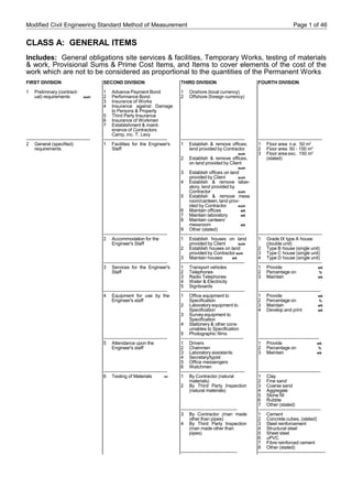
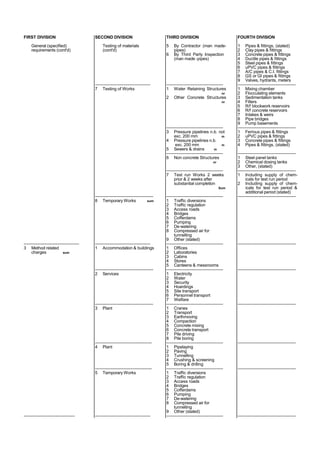
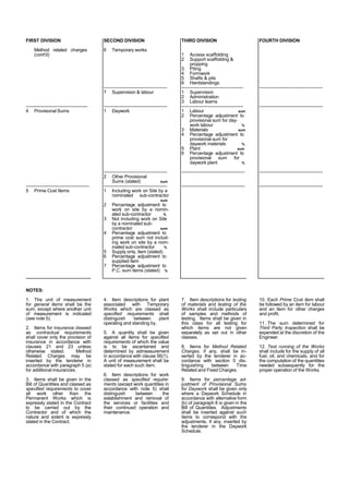
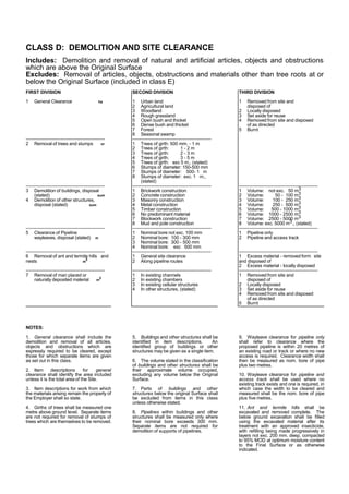
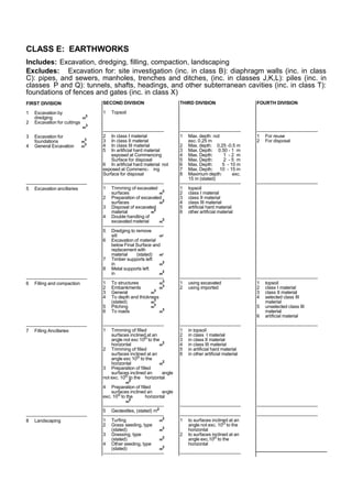
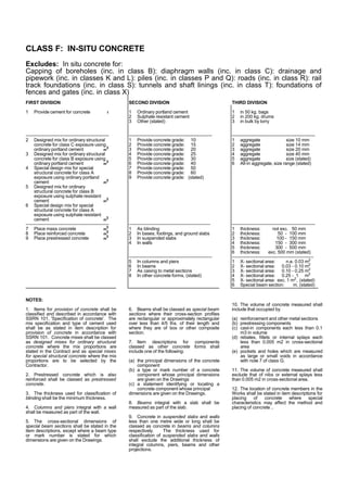
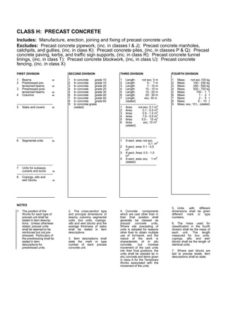
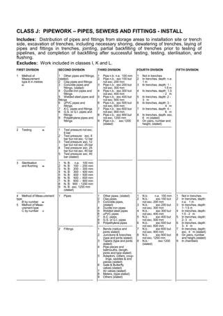
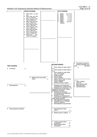
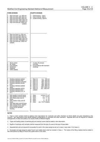
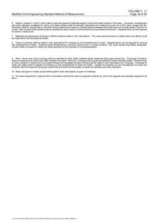
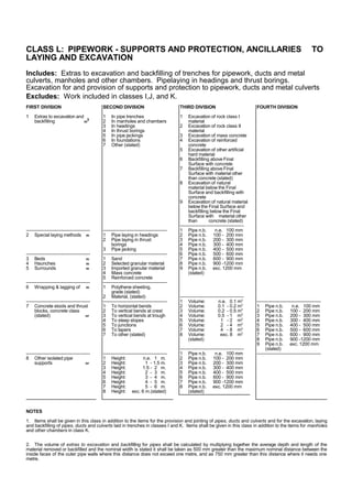
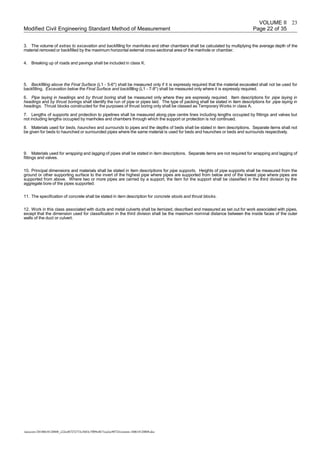
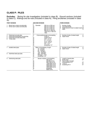
This document provides a classification system and item descriptions for standard methods of measurement for civil engineering works. It includes four divisions for general items, demolition and site clearance, earthworks, and concrete works. The earthworks section includes items for excavation, dredging, filling, compaction, and landscaping. Excavation items are further divided based on material type and location (cuttings, foundations, general). Filling and compaction items specify location and thickness. Landscaping includes preparation of surfaces.
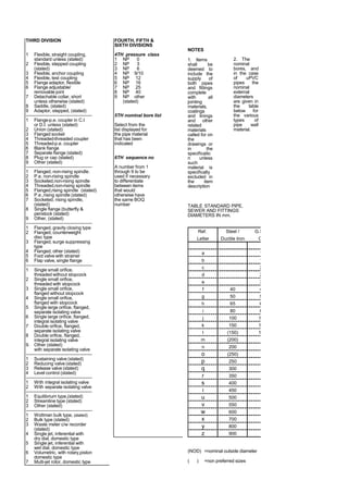

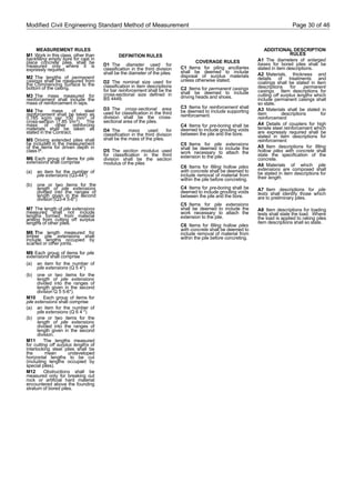

![Modified Civil Engineering Standard Method of Measurement Page 40 of 46
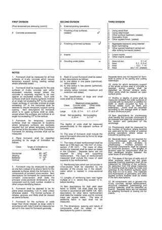
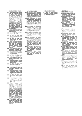
MEASUREMENT RULES
M1 Lengths of sewers shall be
measured along their centre lines be-
tween the inside surfaces of manholes
but shall exclude lengths occupied by
pipes and fittings comprising
backdrops to manholes.
M2 Where work is expressly required to
be carried out by excavation,
crossings, reinstatement and other
sewer-work ancillaries shall be
measured in class K and extras to ex-
cavation and backfilling shall be
measured in class L.
M3 No deduction shall be made from
the areas of sewer surfaces measured
for pointing for openings or voids each
not exceeding 0.5 m2
in area.
M4 External grouting shall be measured
only where grouting is expressly re-
quired to be carried out as a separate
operation from annulus grouting
M5 The volume measured for annulus
grouting shall not include the volume
measured for external grouting
( Y 2 [1-8] [1-9] .3 2).
M6 Interruptions shall be measured only
where a minimum pumping capacity is
expressly required and for periods of
time during normal working hours
wherein the flow in the sewer exceeds
the installed pumping capacity and
work is interrupted.
DEFINITION RULES
D1Items shall be classed as removing
intrusions where artificial intrusions
into the bores of existing sewers are to
be removed prior to renovation.
D2The areas stated in item descriptions
for local internal repairs shall be the
finished surface areas.
D3External grouting shall be grouting of
voids outside the existing sewer from
within the existing sewer other than
voids grouted in the course of annulus
grouting.
D4Annulus grouting shall be grouting of
the annular voids between new linings
and existing sewers and of other voids
grouted in the course of grouting
annular voids.
D5The depth of manholes shall be
measured from the tops of covers to
channel inverts or to tops of base
slabs, whichever is the lower.
COVERAGE RULES
C1 Items for work which is expressly
required to be carried out by excavation
shall be deemed to include preparation
of surfaces, disposal of excavated
material, disposal of excavation,
backfilling and removal of existing
services.
C2 Items for cleaning shall be deemed
to include making good resultant
damage.
C3 Items for removing intrusions shall
be deemed to include making good.
C4 Annulus grouting shall be grouting
of the annular voids between new
linings and existing sewers and of
other voids grouted in the course
of grouting annular voids.
C5 Items for pointing and sewer joint
sealing shall be deemed to include
preparation of joints.
C6 Items for laterals shall be deemed to
include the work involved in connecting
to the lining within 1 m from the inside
face of the lined sewer.
C7 Items for new manholes shall be
deemed to include excavation,
preparation of surfaces, disposal of ex-
cavated material, upholding sides of
excavation, backfilling, concrete, re-
inforcement, form-work, joints, finishes
and reinstatement.
C8 Items for manholes shall be deemed
to include metalwork, different ar-
rangements of inlets and outlets, and
access shafts of different heights and
connection of sewers to manholes.
Items for manholes with backdrops
shall be deemed to include the sewers
and fittings comprising the backdrop.
C9 Items for new manholes replacing
existing manholes shall be deemed to
include breaking out and disposal of
existing manholes.
ADDITIONAL DESCRIPTION RULES
A1The location of the work in each item or
group of items shall be stated so that
the work can be identified by reference
to the Drawings.
A2Principal dimensions, other than
diameter and depth of sewers and pro-
files of sewers shall be identified by
reference to the Drawings.
A3Work expressly required to be carried
out manually or by remotely controlled
methods shall each be so stated in
item descriptions.
A4Item descriptions for work which is
expressly required to be carried out by
excavation shall so state and (except
for manholes) shall state the maximum
depth of excavation in stages of 1 m
measured to the invert of the sewer.
A5Item descriptions for preparation,
stabilisation, renovation and laterals
shall state the material forming of the
existing sewer.
A6Item descriptions for removing
intrusions shall state the materials
forming the intrusions.
A7Where external grouting is carried out
through sewer joints, descriptions of
items for the number of holes shall so
state.
A8Item descriptions for slip-lining, in situ
jointed pipe lining, segmental lining
and stated proprietary lining shall state
the type lining, its minimum finished
internal size and its thickness or grade.
A9Item descriptions for in situ jointed
sewer lining and segmental lining shall
state the offset where the lining is
curved to an offset which exceeds 35
mm per metre.
A10 Item descriptions for jointing laterals
shall state the type of lining to which
the laterals are to be connected and
identify those laterals which are to be
regraded.
A11 Type or mark numbers shall be
stated in item descriptions for man-
holes of which details are given
elsewhere in the Contract. Item
descriptions shall identify different
configurations of manholes.
A12 Types and loading duties of covers
shall be stated in item descriptions for
new manholes.
A13 Item descriptions for existing
manholes shall state details of the work
required.](https://image.slidesharecdn.com/cesmm-180610120808/85/Cesmm-43-320.jpg)


