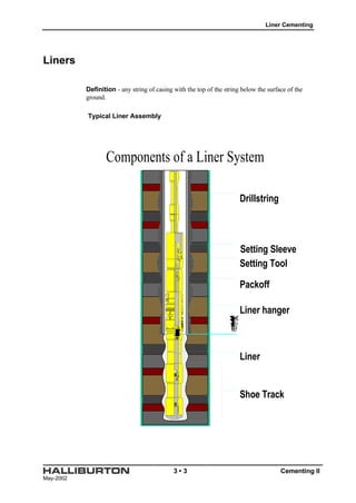
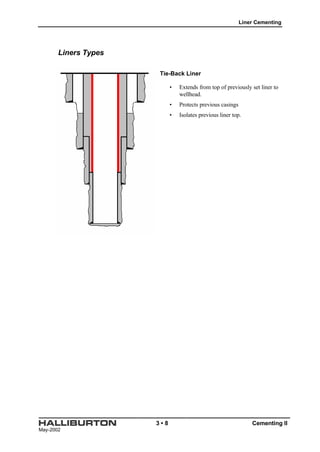
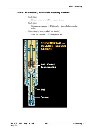
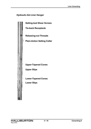
May-2002
3 • 1 Cementing II
Section 3
Liner Cementing
Table of Contents
Introduction.................................................................................................................................... 3-2
Objectives ...................................................................................................................................... 3-2
Liners............................................................................................................................................. 3-3
Definition........................................................................................................................... 3-3
Typical Liner Assembly .................................................................................................... 3-3
Reasons for Running Liners...................................................................................................... 3-4
Liners Types ............................................................................................................................ 3-5
Drilling Liner..................................................................................................................... 3-5
Liners Types ............................................................................................................................ 3-6
Production Liner ............................................................................................................... 3-6
Liners Types ............................................................................................................................ 3-7
Scab or Stub Liner ............................................................................................................ 3-7
Liners Types ............................................................................................................................ 3-8
Tie-Back Liner................................................................................................................... 3-8
Liner Cementing Considerations ............................................................................................... 3-9
Liner Cementing Considerations ............................................................................................. 3-10
Liners: Three Widely Accepted Cementing Methods................................................................ 3-11
Consideration In Selecting Type Of Liner Hanger To Use ....................................................... 3-14
Mechanical-Set Liner Hanger ................................................................................................. 3-15
Hydraulic-Set Liner Hanger.................................................................................................... 3-16
Hydraulic-Set Liner Hanger.................................................................................................... 3-17
Liner Calculation.................................................................................................................... 3-18
Calculate seven parameters:.............................................................................................. 3-18
Example Calculation #4: .................................................................................................. 3-19
Practice Calculation #3 .................................................................................................... 3-23
May-2002
3 • 2 Cementing II
Introduction
The section will
Objectives
After completing this section, you should be able to
Liner Cementing
May-2002
3 • 3 Cementing II
Liners
Definition - any string of casing with the top of the string below the surface of the
ground.
Typical Liner Assembly
Components of a Liner System
Drillstring
Setting Sleeve
Setting Tool
Packoff
Liner hanger
Liner
Shoe Track
Plug System
Liner Cementing
May-2002
3 • 4 Cementing II
Reasons for Running Liners
• Reduced casing cost
• Less ID restriction
- Increased flow rate during drilling and cementing
• Drill with tapered string
• Tensile load may exceed casing specifications.
• Reduced Weight On Wellhead
• Well Construction Requirements
- Sidetracks
- Multi-Laterals
- Slotted Liner
Liner Cementing
May-2002
3 • 5 Cementing II
Liners Types
Drilling Liner
• Set through a section of hole with
further drilling planned.
• Extends intermediate casing.
• Isolates troublesome zones
• Isolates weak or pressurized zones
Liner Cementing
May-2002
3 • 6 Cementing II
Liners Types
Production Liner
• Set through or immediately above
productive interval.
• Serves as completion casing.
Liner Cementing
May-2002
3 • 7 Cementing II
Liners Types
Scab or Stub Liner
• Extends from top of previously set liner to a
point up hole, but not reaching wellhead.
• Repair damaged or parted casing.
Liner Cementing
May-2002
3 • 8 Cementing II
Liners Types
Tie-Back Liner
• Extends from top of previously set liner to
wellhead.
• Protects previous casings
• Isolates previous liner top.
Liner Cementing
May-2002
3 • 9 Cementing II
Liner Cementing Considerations
• Tight annular clearances
- High friction pressures therefore high ECD
- Lost circulation
- Increased Gas Flow Potential
- Differential sticking
- Centralization difficult but critical
• Limited pump rates
- Liner hanger limitations
- High ECD
- Potential for poor mud displacement
• Pipe movement limited
- Liner hanger often set before cementing
- Differential sticking
- Fear of sticking liner off of bottom
• High mud weights
- Densified cement and spacers
- Slurry density at least 1 ppg > mud
• Accurate well data necessary
- Fracture gradient
- Pore pressure
- Caliper log for volume calculations and computer modeling
• Temperature
- BHCT @ liner bottom
- BHST @ liner bottom and top
- High differential may require long waiting times or SCR-100
- BHCT may equal BHST in long horizontal liners.
- Enertech temperature simulator (WT-Drill)
Liner Cementing
May-2002
3 • 10 Cementing II
Liner Cementing Considerations
• Slurry design
- Stable slurry with no free water or solids settling
- Low rheology to minimize ECD but able to suspend solids
- Fluid loss 50-100 cc/30 min; less than 50 cc if gas migration is a concern
or if annular clearance is extremely small
- Compressive strength of 500 psi at liner top before drilling out
- Adequate thickening time allowing for batch mixing, liner hanger
operations, circulating excess cement.
• Contamination concerns
- Always perform contamination tests in lab
- High density muds may be heavily chemically treated
- Contamination results in high viscosity & high ECD
- Spacer in drillpipe at liner hanger if OBM is in annulus
- Avoid SUPERFLUSH spacer on liner applications
Liner Cementing
May-2002
3 • 11 Cementing II
Liners: Three Widely Accepted Cementing Methods
• Single stage:
- Circulate cement to top of liner - reverse excess.
• Single stage:
- Circulate excess cement 10-12 joints above liner-drilled cement after
setting.
• Planned squeeze program: (Tack and Squeeze)
- Lower part cemented - Top part squeezed later.
Liner Cementing
May-2002
3 • 12 Cementing II
Liner Cementing
May-2002
3 • 13 Cementing II
Liner Cementing
May-2002
3 • 14 Cementing II
Consideration In Selecting Type Of Liner Hanger To Use
• Mechanical or hydraulic set
• Single or multiple cone
• Liner rotation and/or reciprocation during cementing
• Hole geometry
• Liner hanger passing through the top of another liner
Liner Cementing
May-2002
3 • 15 Cementing II
Mechanical-Set Liner Hanger
• Set by surface manipulation (rotating to disengage J-slot and slacking off
weight to engage slips)
• To unseat, drillpipe picked up and rotated to get J-slot to the “running in”
position
• Most widely used
Releasing-nut Threads
Sizing Ring
Pack-off Element
Cone
Slips
Automatic J-Latch Cage
Drag Springs
Liner Cementing
May-2002
3 • 16 Cementing II
Hydraulic-Set Liner Hanger
Tie-back Receptacle
Releasing-nut Threads
Plain-Action Setting Collar
Upper-Tapered Cones
Upper Slips
Lower-Tapered Cones
Lower Slips
Setting-tool Shear Screws
Liner Cementing
May-2002
3 • 17 Cementing II
Hydraulic-Set Liner Hanger
• Preferred if one liner is already in well
• Designed to prevent premature setting of slips going into well
• Hydraulic pressure required to set slips (unseat by picking up drillpipe)
• Designs vary, some tools can also be set with ball plug or rotation.
• Not as widely used as mechanical set hangers
Liner Cementing
May-2002
3 • 18 Cementing II
Liner Calculation
Calculate seven parameters:
• Volume of cement required in the annulus: above the liner and in the shoe joint
• Sacks of cement required to achieve the calculated volume
• Mixing fluid required to the mix the cement
• Fluid volume required to pump the drill pipe plug to the top of the liner
• Fluid volume required to pump the casing plug to the landing baffle
• Pressure required to pump the plug to the landing baffle
• Top of the cement when the drill pipe has been pulled out of the hole
Liner Cementing
May-2002
3 • 19 Cementing II
Example Calculation #4:
Cement a 7 inch 32 lb/ft C-75 liner in a 8 1/2 inch open hole. The liner top will be at
11,322 feet. The TD of the 9 5/8 inch 47 lb/ft cased hole is 11,422 feet. The liner TD
will be at; 11,622 feet, there is a 30 foot shoe joint. Cement this with class "H" + .3 %
HR-12 at 16.4 lb/gal. Leave 75 feet of cement on top of the liner when the drill pipe is
pulled out of the hole. The well fluid and displacement fluid will be 11.6 lb/gal mud.
This liner is run on 4 1/2 inch 16.6 lb/ft drill pipe.
• Cubic feet of cement
• Sacks of cement
• Mixing fluid
• Drill pipe displacement
• Liner displacement
• Differential pressure
• TOC when the drill pipe is out
Liner Cementing
May-2002
3 • 20 Cementing II
To Surface
Drilling
Mud
4 1/2"
16.6 lb/ft
Drill Pipe
7" 32 lb/ft
c-75
Liner
8 1/2"
Hole
Tail
Cement
Float
Collar
Float
Shoe11622'
11422'
Top of Liner
11322'
TOC DP in
9 5/8"
47 lb/ft
Casing
TOC DP out
11592'
Volume of Cement
Liner Cementing
May-2002
3 • 21 Cementing II
Left on top 75 ft x .4110 cuft/ft = 30.825 cuft
Over lap 100 ft x .1438 cuft/ft = 14.380 cuft
Open Hole 200 ft x .1268 cuft/ft = 25.360 cuft
Shoe Joint 30 ft x .2025 cuft/ft = 6.075 cuft
Total = 76.640 cuft
Sacks of Cement
76.640 cuft ÷ 1.06 cuft/sk = 72.3019 sacks
Mixing Fluid
72.3019 sks x 4.3 gal/sk ÷ 42 gal/bbl = 7.4023 bbls
Displacement
Drill Pipe 11,322 ft. x .01422 bbl/ft = 160.9988 bbl
Liner 270 ft. x .03600 bbl/ft = 9.7200 bbl
Total = 170.7188 bbl
Liner Cementing
May-2002
3 • 22 Cementing II
Differential Pressure
Cased hole to drill pipe annulus factor.
0.4110 cuft/ft - .1104 cuft/ft = .3006 cuft/ft
HOC above liner 30.825 cuft ÷ .3006 cuft/ft = 102.5449 ft
HOC to Liner top = 300.0000 ft
Total HOC = 402.5449 ft
Hydrostatic pressure outside the liner and drill pipe
Well Fluid 11,219.4550 ft x .6026 psi/ft = 6760.8436 psi
Cement 402.5449 ft x .8519 psi/ft = 342.9280 psi
Total = 7103.7716 psi
Hydrostatic pressure inside the liner and drill pipe
Displacement 11,592 ft x .6026 psi/ft = 6985.3392 psi
Cement 30 ft x .8519 psi/ft = 25.5570 psi
Total = 7010.8962 psi
Differential Pressure
7103.7716 psi
- 7010.8962 psi
92.8754 psi
Top of cement when drill pipe is pulled
11,322 feet
- 75 feet
11,247 feet
Liner Cementing
May-2002
3 • 23 Cementing II
Practice Calculation #3
Cement a 9 5/8 inch 47 lb/ft N-80 liner in a 12 1/2 inch open hole (average hole size).
Allow an additional 9% of the open hole annulus volume for excess. The liner top will
be at 11,956 feet. The TD of the 13 3/8 inch 68 lb/ft cased hole is 12,076 feet. The
liner TD will be at 12,856 feet, there is a 30 foot shoe joint. Cement this with class "G"
+ .75 % CFR-2 at 17 lb/gal. Leave 100 feet of cement on top of the liner. The well
fluid and displacement fluid will be 11.3 lb/gal mud. This liner is run on 4 inch 14 lb/ft
drill pipe.
• Cubic feet of cement
• Sacks of cement
• Mixing fluid
• Drill pipe displacement
• Liner displacement
• Differential pressure
• TOC when the drill pipe is out
Liner Cementing
May-2002
3 • 24 Cementing II
To Surface
Liner Cementing
May-2002
3 • 25 Cementing II
Practice Calculation #4
Cement a 5.0 inch 18.0 lb/ft liner in a 7 inch open hole. The annulus is washed out
12%. The liner top will be at 12,610 feet. The TD of the 8 5/8 inch 40 lb/ft cased
hole is 12,685 feet. The liner TD will be 13,310 feet, there is a 30 foot shoe joint.
Cement this with class "A" + 0.4% HR-4. Leave 100 feet of cement on top of the
liner. The well fluid and displacement fluid are 10.2 lb/gal mud. This liner is run on 4
1/2 inch 20.0 lb/ft drill pipe.
• Cubic feet of cement
• Sacks of cement
• Mixing fluid
• Drill pipe displacement
• Liner displacement
• Differential pressure
• TOC when the drill pipe is out
Liner Cementing
May-2002
3 • 26 Cementing II
To Surface

Cementing ii section 3

  • 1.
    May-2002 3 • 1Cementing II Section 3 Liner Cementing Table of Contents Introduction.................................................................................................................................... 3-2 Objectives ...................................................................................................................................... 3-2 Liners............................................................................................................................................. 3-3 Definition........................................................................................................................... 3-3 Typical Liner Assembly .................................................................................................... 3-3 Reasons for Running Liners...................................................................................................... 3-4 Liners Types ............................................................................................................................ 3-5 Drilling Liner..................................................................................................................... 3-5 Liners Types ............................................................................................................................ 3-6 Production Liner ............................................................................................................... 3-6 Liners Types ............................................................................................................................ 3-7 Scab or Stub Liner ............................................................................................................ 3-7 Liners Types ............................................................................................................................ 3-8 Tie-Back Liner................................................................................................................... 3-8 Liner Cementing Considerations ............................................................................................... 3-9 Liner Cementing Considerations ............................................................................................... 3-9 Liner Cementing Considerations ............................................................................................. 3-10 Liners: Three Widely Accepted Cementing Methods................................................................ 3-11 Consideration In Selecting Type Of Liner Hanger To Use ....................................................... 3-14 Mechanical-Set Liner Hanger ................................................................................................. 3-15 Hydraulic-Set Liner Hanger.................................................................................................... 3-16 Hydraulic-Set Liner Hanger.................................................................................................... 3-16 Hydraulic-Set Liner Hanger.................................................................................................... 3-17 Liner Calculation.................................................................................................................... 3-18 Calculate seven parameters:.............................................................................................. 3-18 Example Calculation #4: .................................................................................................. 3-19 Practice Calculation #3 .................................................................................................... 3-23
  • 2.
    May-2002 3 • 2Cementing II Introduction The section will Objectives After completing this section, you should be able to
  • 3.
    Liner Cementing May-2002 3 •3 Cementing II Liners Definition - any string of casing with the top of the string below the surface of the ground. Typical Liner Assembly Components of a Liner System Drillstring Setting Sleeve Setting Tool Packoff Liner hanger Liner Shoe Track Plug System
  • 4.
    Liner Cementing May-2002 3 •4 Cementing II Reasons for Running Liners • Reduced casing cost • Less ID restriction - Increased flow rate during drilling and cementing • Drill with tapered string • Tensile load may exceed casing specifications. • Reduced Weight On Wellhead • Well Construction Requirements - Sidetracks - Multi-Laterals - Slotted Liner
  • 5.
    Liner Cementing May-2002 3 •5 Cementing II Liners Types Drilling Liner • Set through a section of hole with further drilling planned. • Extends intermediate casing. • Isolates troublesome zones • Isolates weak or pressurized zones
  • 6.
    Liner Cementing May-2002 3 •6 Cementing II Liners Types Production Liner • Set through or immediately above productive interval. • Serves as completion casing.
  • 7.
    Liner Cementing May-2002 3 •7 Cementing II Liners Types Scab or Stub Liner • Extends from top of previously set liner to a point up hole, but not reaching wellhead. • Repair damaged or parted casing.
  • 8.
    Liner Cementing May-2002 3 •8 Cementing II Liners Types Tie-Back Liner • Extends from top of previously set liner to wellhead. • Protects previous casings • Isolates previous liner top.
  • 9.
    Liner Cementing May-2002 3 •9 Cementing II Liner Cementing Considerations • Tight annular clearances - High friction pressures therefore high ECD - Lost circulation - Increased Gas Flow Potential - Differential sticking - Centralization difficult but critical • Limited pump rates - Liner hanger limitations - High ECD - Potential for poor mud displacement • Pipe movement limited - Liner hanger often set before cementing - Differential sticking - Fear of sticking liner off of bottom • High mud weights - Densified cement and spacers - Slurry density at least 1 ppg > mud • Accurate well data necessary - Fracture gradient - Pore pressure - Caliper log for volume calculations and computer modeling • Temperature - BHCT @ liner bottom - BHST @ liner bottom and top - High differential may require long waiting times or SCR-100 - BHCT may equal BHST in long horizontal liners. - Enertech temperature simulator (WT-Drill)
  • 10.
    Liner Cementing May-2002 3 •10 Cementing II Liner Cementing Considerations • Slurry design - Stable slurry with no free water or solids settling - Low rheology to minimize ECD but able to suspend solids - Fluid loss 50-100 cc/30 min; less than 50 cc if gas migration is a concern or if annular clearance is extremely small - Compressive strength of 500 psi at liner top before drilling out - Adequate thickening time allowing for batch mixing, liner hanger operations, circulating excess cement. • Contamination concerns - Always perform contamination tests in lab - High density muds may be heavily chemically treated - Contamination results in high viscosity & high ECD - Spacer in drillpipe at liner hanger if OBM is in annulus - Avoid SUPERFLUSH spacer on liner applications
  • 11.
    Liner Cementing May-2002 3 •11 Cementing II Liners: Three Widely Accepted Cementing Methods • Single stage: - Circulate cement to top of liner - reverse excess. • Single stage: - Circulate excess cement 10-12 joints above liner-drilled cement after setting. • Planned squeeze program: (Tack and Squeeze) - Lower part cemented - Top part squeezed later.
  • 12.
  • 13.
  • 14.
    Liner Cementing May-2002 3 •14 Cementing II Consideration In Selecting Type Of Liner Hanger To Use • Mechanical or hydraulic set • Single or multiple cone • Liner rotation and/or reciprocation during cementing • Hole geometry • Liner hanger passing through the top of another liner
  • 15.
    Liner Cementing May-2002 3 •15 Cementing II Mechanical-Set Liner Hanger • Set by surface manipulation (rotating to disengage J-slot and slacking off weight to engage slips) • To unseat, drillpipe picked up and rotated to get J-slot to the “running in” position • Most widely used Releasing-nut Threads Sizing Ring Pack-off Element Cone Slips Automatic J-Latch Cage Drag Springs
  • 16.
    Liner Cementing May-2002 3 •16 Cementing II Hydraulic-Set Liner Hanger Tie-back Receptacle Releasing-nut Threads Plain-Action Setting Collar Upper-Tapered Cones Upper Slips Lower-Tapered Cones Lower Slips Setting-tool Shear Screws
  • 17.
    Liner Cementing May-2002 3 •17 Cementing II Hydraulic-Set Liner Hanger • Preferred if one liner is already in well • Designed to prevent premature setting of slips going into well • Hydraulic pressure required to set slips (unseat by picking up drillpipe) • Designs vary, some tools can also be set with ball plug or rotation. • Not as widely used as mechanical set hangers
  • 18.
    Liner Cementing May-2002 3 •18 Cementing II Liner Calculation Calculate seven parameters: • Volume of cement required in the annulus: above the liner and in the shoe joint • Sacks of cement required to achieve the calculated volume • Mixing fluid required to the mix the cement • Fluid volume required to pump the drill pipe plug to the top of the liner • Fluid volume required to pump the casing plug to the landing baffle • Pressure required to pump the plug to the landing baffle • Top of the cement when the drill pipe has been pulled out of the hole
  • 19.
    Liner Cementing May-2002 3 •19 Cementing II Example Calculation #4: Cement a 7 inch 32 lb/ft C-75 liner in a 8 1/2 inch open hole. The liner top will be at 11,322 feet. The TD of the 9 5/8 inch 47 lb/ft cased hole is 11,422 feet. The liner TD will be at; 11,622 feet, there is a 30 foot shoe joint. Cement this with class "H" + .3 % HR-12 at 16.4 lb/gal. Leave 75 feet of cement on top of the liner when the drill pipe is pulled out of the hole. The well fluid and displacement fluid will be 11.6 lb/gal mud. This liner is run on 4 1/2 inch 16.6 lb/ft drill pipe. • Cubic feet of cement • Sacks of cement • Mixing fluid • Drill pipe displacement • Liner displacement • Differential pressure • TOC when the drill pipe is out
  • 20.
    Liner Cementing May-2002 3 •20 Cementing II To Surface Drilling Mud 4 1/2" 16.6 lb/ft Drill Pipe 7" 32 lb/ft c-75 Liner 8 1/2" Hole Tail Cement Float Collar Float Shoe11622' 11422' Top of Liner 11322' TOC DP in 9 5/8" 47 lb/ft Casing TOC DP out 11592' Volume of Cement
  • 21.
    Liner Cementing May-2002 3 •21 Cementing II Left on top 75 ft x .4110 cuft/ft = 30.825 cuft Over lap 100 ft x .1438 cuft/ft = 14.380 cuft Open Hole 200 ft x .1268 cuft/ft = 25.360 cuft Shoe Joint 30 ft x .2025 cuft/ft = 6.075 cuft Total = 76.640 cuft Sacks of Cement 76.640 cuft ÷ 1.06 cuft/sk = 72.3019 sacks Mixing Fluid 72.3019 sks x 4.3 gal/sk ÷ 42 gal/bbl = 7.4023 bbls Displacement Drill Pipe 11,322 ft. x .01422 bbl/ft = 160.9988 bbl Liner 270 ft. x .03600 bbl/ft = 9.7200 bbl Total = 170.7188 bbl
  • 22.
    Liner Cementing May-2002 3 •22 Cementing II Differential Pressure Cased hole to drill pipe annulus factor. 0.4110 cuft/ft - .1104 cuft/ft = .3006 cuft/ft HOC above liner 30.825 cuft ÷ .3006 cuft/ft = 102.5449 ft HOC to Liner top = 300.0000 ft Total HOC = 402.5449 ft Hydrostatic pressure outside the liner and drill pipe Well Fluid 11,219.4550 ft x .6026 psi/ft = 6760.8436 psi Cement 402.5449 ft x .8519 psi/ft = 342.9280 psi Total = 7103.7716 psi Hydrostatic pressure inside the liner and drill pipe Displacement 11,592 ft x .6026 psi/ft = 6985.3392 psi Cement 30 ft x .8519 psi/ft = 25.5570 psi Total = 7010.8962 psi Differential Pressure 7103.7716 psi - 7010.8962 psi 92.8754 psi Top of cement when drill pipe is pulled 11,322 feet - 75 feet 11,247 feet
  • 23.
    Liner Cementing May-2002 3 •23 Cementing II Practice Calculation #3 Cement a 9 5/8 inch 47 lb/ft N-80 liner in a 12 1/2 inch open hole (average hole size). Allow an additional 9% of the open hole annulus volume for excess. The liner top will be at 11,956 feet. The TD of the 13 3/8 inch 68 lb/ft cased hole is 12,076 feet. The liner TD will be at 12,856 feet, there is a 30 foot shoe joint. Cement this with class "G" + .75 % CFR-2 at 17 lb/gal. Leave 100 feet of cement on top of the liner. The well fluid and displacement fluid will be 11.3 lb/gal mud. This liner is run on 4 inch 14 lb/ft drill pipe. • Cubic feet of cement • Sacks of cement • Mixing fluid • Drill pipe displacement • Liner displacement • Differential pressure • TOC when the drill pipe is out
  • 24.
    Liner Cementing May-2002 3 •24 Cementing II To Surface
  • 25.
    Liner Cementing May-2002 3 •25 Cementing II Practice Calculation #4 Cement a 5.0 inch 18.0 lb/ft liner in a 7 inch open hole. The annulus is washed out 12%. The liner top will be at 12,610 feet. The TD of the 8 5/8 inch 40 lb/ft cased hole is 12,685 feet. The liner TD will be 13,310 feet, there is a 30 foot shoe joint. Cement this with class "A" + 0.4% HR-4. Leave 100 feet of cement on top of the liner. The well fluid and displacement fluid are 10.2 lb/gal mud. This liner is run on 4 1/2 inch 20.0 lb/ft drill pipe. • Cubic feet of cement • Sacks of cement • Mixing fluid • Drill pipe displacement • Liner displacement • Differential pressure • TOC when the drill pipe is out
  • 26.
    Liner Cementing May-2002 3 •26 Cementing II To Surface