Downloaded 215 times


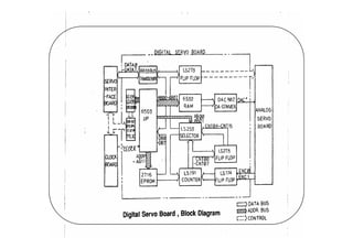


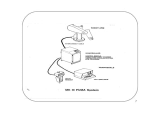


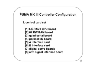


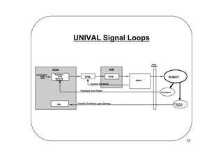

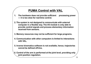
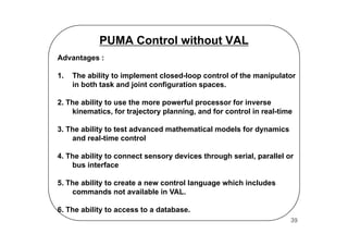
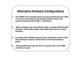
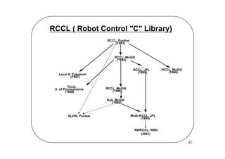


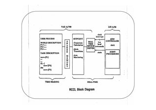


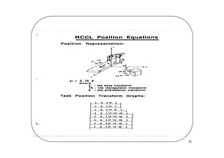
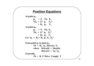


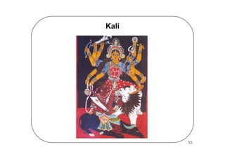


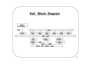


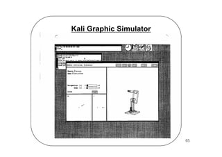


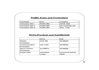


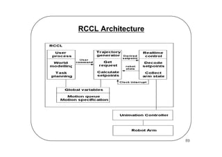


This document discusses programming and controlling PUMA robot arms using various software libraries and controllers. It provides an overview of PUMA robot arms, their controllers including the Mark I, Mark II, Mark III, and UNIVAL controllers. It then discusses various software libraries for controlling PUMA arms including VAL, RCCL, Level II, Kali, and ALVIN. It provides block diagrams and descriptions of how these different software libraries interface with and control PUMA robot arms.


![[2차] 2013년 워드프레스 템플릿 시장 열릴 것인가?](https://cdn.slidesharecdn.com/ss_thumbnails/20132-130421185112-phpapp01-thumbnail.jpg?width=640&height=640&fit=bounds)

![[02회][제대로워드프레스][세미나]](https://cdn.slidesharecdn.com/ss_thumbnails/02-120614224115-phpapp01-thumbnail.jpg?width=640&height=640&fit=bounds)


