JOINT SHEAR STRENGTH AS PER ACI 318 CODE final.pptx
1.
JOINT SHEAR
STRENGTH ASPER
ACI 318 CODE
SUBMITTED BY,
VAISHNAVI K P
ROLL NO: 18
MTECH STRUCTURAL
ENGINEERING
2.
CONTENTS
• INTRODUCTION
• GENERALPROVISIONS FOR BEAM-COLUMN AND SLAB-COLUMN
JOINTS (AS PER ACI 318-19)
• DETAILING OF JOINTS(AS PER ACI 318, SECTION 15.3)
• STRENGTH REQUIREMENTS FOR BEAM-COLUMN JOINTS (AS PER
ACI 318, SECTION 15.4.1)
• DESIGN SHEAR STRENGTH
• CONCLUSION
3.
INTRODUCTION
• What isJoint Shear Strength?
• The ability of concrete beam-column/slab-column joints to resist applied
shear forces.
• Critical for the safety and performance of reinforced concrete structures.
• Why is it Important?
• Joints are Weak Zones: Due to intersecting members, joints often experience
stress concentrations and cracking.
• Failure Prevention: A weak joint can cause the entire structure to collapse.
4.
HOW DOES ACI318 ADDRESS JOINT SHEAR
STRENGTH
• Typical beam-column joints are defined as Type 1 and Type 2 joints, as per
ACI 352R-02
• a) Type 1 Joints : these joints have members designed to satisfy strength
requirements, without significant inelastic deformation. These are non-
seismic joints.
• b) Type 2 Joints : these joints have members that are required to dissipate
energy through reversals of deformation into the inelastic range. These are
seismic joints.
5.
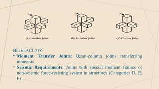
But in ACI318
• Moment Transfer Joints: Beam-column joints transferring
moments
• Seismic Requirements: Joints with special moment frames or
non-seismic force-resisting system in structures (Categories D, E,
F)
6.
GENERAL PROVISIONS FORBEAM-COLUMN AND
SLAB-COLUMN JOINTS (AS PER ACI 318-19)
• Detailing and Strength Requirements (15.2.1)
Beam-column joints must comply with two critical aspects:
• Detailing provisions specified in Section 15.3.
• Strength requirements specified in Section 15.4.
• Transfer of Column Axial Force (15.2.2)
Beam-column and slab-column joints must be capable of transferring the axial
force from the column to the floor system.
7.
3. Shear fromMoment Transfer (15.2.3)
If lateral forces (like wind or earthquakes) or gravity loads cause moment
transfer at the joint, the resulting shear force must be included in the design of
the joint.
4. Effects of Opening and Closing Moments at Corner Joints (15.2.4)
At corner joints (where two members meet at a corner), the effects of opening
and closing moments within the joint must be considered.
• Closing moments compress the joint.
• Opening moments tend to "pull apart" the joint.
8.
5. Deep BeamConditions and Strut-and-Tie Method (15.2.5)
If a beam framing into the joint has a depth exceeding twice the column depth
6. Continuity from Column Extension
If a column extension is assumed to provide continuity through a joint
(a) The column must extend at least one column depth ( ) above the joint in
ℎ
the direction of the joint shear.
(b) Longitudinal and transverse reinforcement from the column below must be
continued through the extension.
7. Continuity from Beam Extension (15.2.7)
If a beam extension is assumed to provide continuity through a joint in the
direction of joint shear
9.
DETAILING OF JOINTS(ASPER ACI 318, SECTION
15.3)
• Beam-Column Joint Transverse Reinforcement
• Conditions When Transverse Reinforcement is not required
• (a) The joint is confined by transverse beams (other beams help resist the
shear force).
• (b) The joint is not part of the seismic-force-resisting system (it doesn't
play a major role in withstanding earthquakes).
• (c) The joint is not in a structure in Seismic Design Categories D, E, or F
(areas with higher earthquake risk).
10.
DETAILING OF JOINTS(ASPER ACI 318, SECTION
15.3)
• Reinforcement Requirements
• Transverse reinforcement must be provided and can be in the form of
• Ties (short bars bent to form a loop)
• Spirals (coiled reinforcement)
• Hoops (circular reinforcement)
These must meet the requirements for these types of reinforcement as specified
in 25.7.
11.
DETAILING OF JOINTS(ASPER ACI 318, SECTION
15.3)
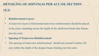
• Reinforcement Layers
• At least two layers of horizontal transverse reinforcement should be placed
in the joint, extending across the depth of the shallowest beam that frames
into the joint.
• Spacing of Transverse Reinforcement
• The spacing of transverse reinforcement should not exceed 8 inches (20
cm) within the depth of the deepest beam framing into the joint.
12.
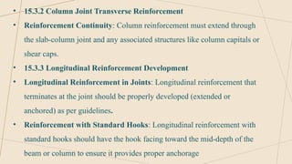
• 15.3.2 ColumnJoint Transverse Reinforcement
• Reinforcement Continuity: Column reinforcement must extend through
the slab-column joint and any associated structures like column capitals or
shear caps.
• 15.3.3 Longitudinal Reinforcement Development
• Longitudinal Reinforcement in Joints: Longitudinal reinforcement that
terminates at the joint should be properly developed (extended or
anchored) as per guidelines.
• Reinforcement with Standard Hooks: Longitudinal reinforcement with
standard hooks should have the hook facing toward the mid-depth of the
beam or column to ensure it provides proper anchorage
13.
STRENGTH REQUIREMENTS FORBEAM-COLUMN
JOINTS (AS PER ACI 318, SECTION 15.4.1)
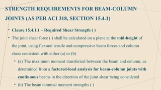
• Clause 15.4.1.1 – Required Shear Strength ( )
• The joint shear force ( ) shall be calculated on a plane at the mid-height of
the joint, using flexural tensile and compressive beam forces and column
shear consistent with either (a) or (b)
• (a) The maximum moment transferred between the beam and column, as
determined from a factored-load analysis for beam-column joints with
continuous beams in the direction of the joint shear being considered
• (b) The beam nominal moment strengths ( )
14.
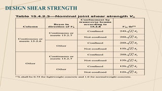
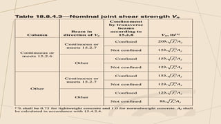
DESIGN SHEAR STRENGTH
•Design Shear Strength Condition[15.4.2]
• Design shear strength of cast-in-place beam column joints shall satisfy:
• shall be accordance with 21.2.1 for shear
• = Nominal shear strength of the joint
• = Factored joint shear force
• of the joint shall be calculated in accordance with Table 15.4.2.3.
This ensures the joint has adequate capacity to resist the applied shear forces.
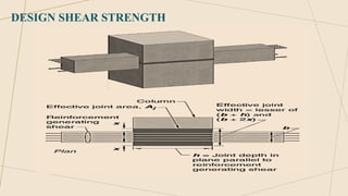
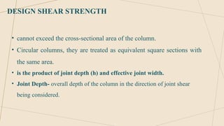
DESIGN SHEAR STRENGTH
•cannot exceed the cross-sectional area of the column.
• Circular columns, they are treated as equivalent square sections with
the same area.
• is the product of joint depth (h) and effective joint width.
• Joint Depth- overall depth of the column in the direction of joint shear
being considered.
20.
DESIGN SHEAR STRENGTH
•EFFECTIVE JOINT WIDTH
• When the beam is wider than the column: Use the overall width of the
column.
• When the column is wider than the beam: Effective joint width is limited
to the lesser of
• (a) Beam width + joint depth
• (b) Twice the perpendicular distance from the longitudinal axis of the
beam to the nearest side face of the column.
21.
TRANSFER OF COLUMNAXIAL FORCE THROUGH
THE FLOOR SYSTEM [15.5]
• 15.5.1 If ′ of the floor system is less than 0.7 ′ of a column,
𝑓𝑐 𝑓𝑐
transmission of axial force through the floor system shall be in accordance
with (a), (b), or (c)
(a) Use Stronger Concrete at the Column Location
• Place the same concrete strength as the column in the floor system near
the column
• Extend this stronger concrete 12 inches (300 mm) into the floor system
and fully integrate it with the floor concrete
22.
(b) Design UsingLower Strength Concrete
• Assume the weaker floor concrete strength to calculate the column's load-
carrying capacity
• Add vertical dowels and transverse reinforcement to strengthen the joint
and ensure it can handle the load
(c) Use an Adjusted Concrete Strength for Joints
For beam-column or slab-column joints supported on all four sides Use an
assumed strength of
• 75% of the column concrete strength + 25% of the floor concrete strength
• The column concrete strength cannot be more than 1.5 times the floor
system concrete strength
23.
CONCLUSION
• Beam-column andslab-column joints are crucial for structural stability, and
their design must address shear forces to prevent failures.
• ACI 318 provides specific provisions for joint design, including strength
requirements and reinforcement guidelines based on the type and location
of the joint.
• The code also outlines methods for transferring axial forces through the
floor system, ensuring joints can effectively carry loads, even in cases
where floor concrete strength is lower than that of the column.
![DESIGN SHEAR STRENGTH
• Design Shear Strength Condition[15.4.2]
• Design shear strength of cast-in-place beam column joints shall satisfy:
• shall be accordance with 21.2.1 for shear
• = Nominal shear strength of the joint
• = Factored joint shear force
• of the joint shall be calculated in accordance with Table 15.4.2.3.
This ensures the joint has adequate capacity to resist the applied shear forces.](https://image.slidesharecdn.com/jointshearstrengthasperaci318codefinal-250421201657-ad4515b2/85/JOINT-SHEAR-STRENGTH-AS-PER-ACI-318-CODE-final-pptx-14-320.jpg)
![TRANSFER OF COLUMN AXIAL FORCE THROUGH
THE FLOOR SYSTEM [15.5]
• 15.5.1 If ′ of the floor system is less than 0.7 ′ of a column,
𝑓𝑐 𝑓𝑐
transmission of axial force through the floor system shall be in accordance
with (a), (b), or (c)
(a) Use Stronger Concrete at the Column Location
• Place the same concrete strength as the column in the floor system near
the column
• Extend this stronger concrete 12 inches (300 mm) into the floor system
and fully integrate it with the floor concrete](https://image.slidesharecdn.com/jointshearstrengthasperaci318codefinal-250421201657-ad4515b2/85/JOINT-SHEAR-STRENGTH-AS-PER-ACI-318-CODE-final-pptx-21-320.jpg)