This document provides instructions for configuring a CCIE RSV5 lab exam. It includes requirements for configuring layer 2 and layer 3 technologies like VTP, VLANs, STP, OSPF, EIGRP on routers and switches located in two autonomous systems - AS12345 and AS34567. The configuration aims to satisfy routing, redundancy and security objectives specified in the document.
![© 2014-2015 CCIEREALLABWORKBOOK.COM
October 10,
2014
© 2014-2015 CCIEREALLABWORKBOOK.COM 8
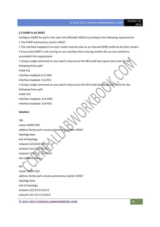
Section 2 (layer 3 technology
2.1 OSPF in AS12345
Configure OSPFv2 area 0 in ACME headquarters (AS12345) according to the following requirements
• Configure the OSPF process id to 12345 and set the router-id to interface Loopback 0 on all seven
routers
• The interface Loopback 0 at each router must be seen as an internal OSPF prefix by all other routers
• Ensure that OSPF is not running on any interface that is facing another AS use any method to
accomplish this requirement
• SW1 and SW2 must not participate in routing at all
• Do not change the default OSPF cost of any interface in AS12345
• R1 must see the following OSPF routes in its routing table
R1# sh ip route OSPF
123.0.0.0/8 is variably subnetted, 17 subnets, 2 masks
0 123.2.2.2/32 [110/21] via 123.10.1.14d20h Ethernet e0/2
0 123.3.3.3/32 [110/21] via 123.10.1.6 4d20h Ethernet e0/1
0 123.4.4.4132 [110/21]via 123.10.1.1 4d20h Ethernet e0/1
0 123.5.5.5132 [110121] via 123.10.1.6 4d20h Ethernet e0/1
0 123.6.6.6132 [110/21] via 123.10.1.14d20h Ethernet e0/1
0 123.7.7.7/32 [110/21] via 123.10.1.6 4d20h Ethernet e0/1
0 123.10.1.8/30 [110/30] via 123.10.1.6 4d20h Ethernet e0/1
[110/30] via 123.10.1.1 4d20h Ethernet e0/2
0 123.10.1.12130 [110/20] via 123.10.1.6 4d20h Ethernet e0/1
0 123.10.1.16130 [110/20] via 123.10.1.1 4d20h Ethernet e0/1
0 123.10.1.20/30 [110/20] via 123.10.1.14d20h Ethernet e0/1
0 123.10.1.24/30 [110/30] via 123.10.1.6 4d20h Ethernet e0/1
[110/30] via 123.10.1.1 4d20h Ethernet e0/1
0 123.10.1.28/30 [110/20] via 123.10.1.6 4d20h Ethernet e0/1
0 123.2.2.2/8 [110/21] via 123.10.1.1 4d20h Ethernet e0/1
0 123.3.3.318 [110/21] via 123.10.1.6 4d20h Ethernet e0/1
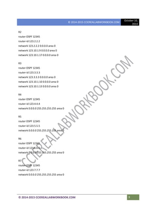
Solution:
R1:
router OSPF 12345
router-id 123.1.1.1
network 0.0.0.0 255.255.255.255 area 0](https://image.slidesharecdn.com/demolab1-151206072924-lva1-app6892/85/CCIE-Real-LAB-LAB-1-1-CCIEREALLABWORKBOOK-COM-8-320.jpg)