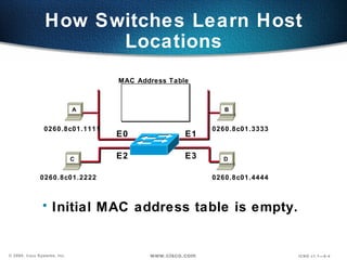
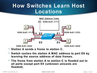
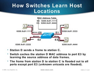
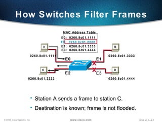
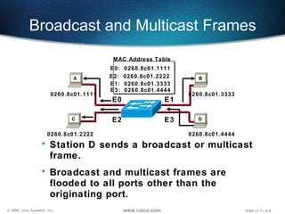
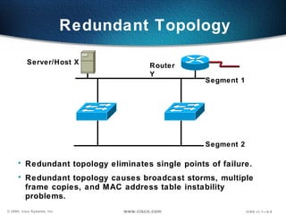
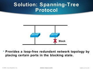
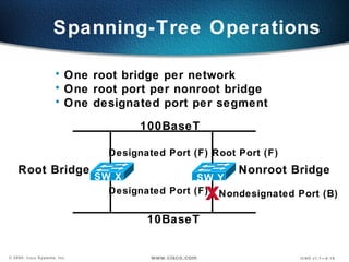
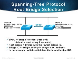
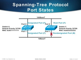
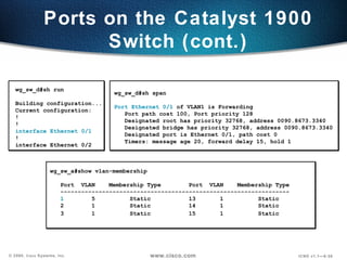
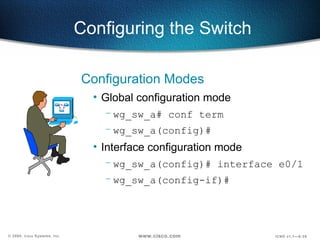
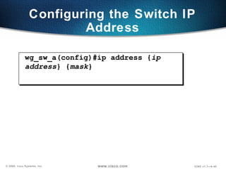
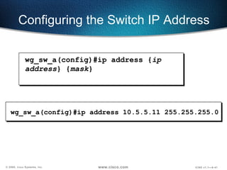
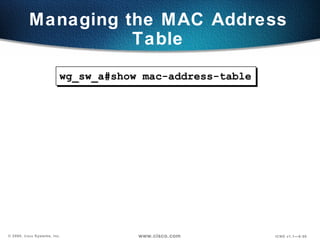
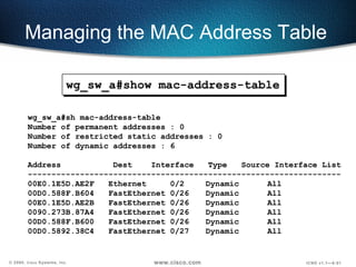
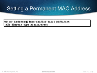
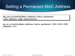
http://www.ccna-4.tk
Objectives Upon completion of this chapter, you will be able to perform the following tasks: Describe Layer 2 switching (bridging) operations. Describe the Catalyst 1900 switch operations. Describe the Catalyst 1900 switch default configuration. Configure the  Catalyst  1900 switch. Use show commands to verify  Catalyst  1900 switch configuration and operations.
Address learning Forward/filter decision Loop avoidance Three Switch Functions
How Switches Learn Host Locations Initial MAC address table is empty. MAC Address Table 0260.8c01.1111 0260.8c01.2222 0260.8c01.3333 0260.8c01.4444 E0 E1 E2 E3 A B C D
How Switches Learn Host Locations Station A sends a frame to station C. Switch caches the station A MAC address to port E0 by learning the source address of data frames. The frame from station A to station C is flooded out to all ports except port E0 (unknown unicasts are flooded). MAC Address Table 0260.8c01.1111 0260.8c01.2222 0260.8c01.3333 0260.8c01.4444 E0:  0260.8c01.1111 E0 E1 E2 E3 D C B A
How Switches Learn Host Locations Station D sends a frame to station C. Switch caches the station D MAC address to port E3 by learning the source address of data frames. The frame from station D to station C is flooded out to all ports except port E3 (unknown unicasts are flooded). MAC Address Table 0260.8c01.1111 0260.8c01.2222 0260.8c01.3333 0260.8c01.4444 E0:  0260.8c01.1111 E3:  0260.8c01.4444 E0 E1 E2 E3 D C A B
How Switches Filter Frames Station A sends a frame to station C. Destination is known; frame is not flooded. E0:  0260.8c01.1111 E2:  0260.8c01.2222 E1:  0260.8c01.3333 E3:  0260.8c01.4444 0260.8c01.1111 0260.8c01.2222 0260.8c01.3333 0260.8c01.4444 E0 E1 E2 E3 X X D C A B MAC Address Table
Broadcast and Multicast Frames Station D sends a broadcast or multicast frame. Broadcast and multicast frames are flooded to all ports other than the originating port. 0260.8c01.1111 0260.8c01.2222 0260.8c01.3333 0260.8c01.4444 E0 E1 E2 E3 D C A B E0:  0260.8c01.1111 E2:  0260.8c01.2222 E1:  0260.8c01.3333 E3:  0260.8c01.4444 MAC Address Table
Redundant Topology  Redundant topology eliminates single points of failure. Redundant topology causes broadcast storms, multiple frame copies, and MAC address table instability problems. Segment 1 Segment 2 Server/Host X Router Y
Broadcast Storms Segment 1 Segment 2 Server/Host X Router Y Broadcast Switch A Switch B Host X sends a Broadcast
Broadcast Storms Segment 1 Segment 2 Server/Host X Router Y Broadcast Switches continue to propagate broadcast traffic over and over. Switch A Switch B
Multiple Frame Copies Segment 1 Segment 2 Server/Host X Router Y Unicast Switch A Switch B Host X sends an unicast frame to router Y. Router Y MAC address has not been learned by either switch yet.
Multiple Frame Copies Segment 1 Segment 2 Server/Host X Router Y Switch A Switch B Host X sends an unicast frame to router Y. Router Y MAC address has not been learned by either switch yet. Router Y will receive two copies of the same frame. Unicast Unicast Unicast
MAC Database Instability Segment 1 Segment 2 Server/Host X Router Y Unicast Unicast Switch A Switch B Host X sends an unicast frame to router Y. Router Y MAC address has not been learned by either switch yet. Switch A and B learn the host X MAC address on port 0. Port 0 Port 1 Port 0 Port 1
MAC Database Instability Segment 1 Segment 2 Server/Host X Router Y Unicast Unicast Switch A Switch B Host X sends an unicast frame to router Y. Router Y MAC address has not been learned by either switch yet. Switch A and B learn the host X MAC address on port 0. The frame to router Y is flooded. Switches A and B incorrectly learn the host X MAC address on port 1. Port 0 Port 1 Port 0 Port 1
Complex topology can cause multiple loops to occur. Layer 2 has no mechanism to stop the loop. Multiple Loop Problems Server/Host Workstations Loop Loop Loop Broadcast
Solution: Spanning-Tree Protocol Provides a loop-free redundant network topology by  placing certain ports in the blocking state. Block x
Spanning-Tree Operations One root bridge per network One root port per nonroot bridge One designated port per segment x Designated Port (F) Root Port (F) Designated Port (F) Nondesignated Port (B) Root Bridge Nonroot Bridge SW X SW Y 100BaseT 10BaseT
Switch Y Default Priority 32768  (8000 hex) MAC 0c0022222222 Switch X Default Priority 32768  (8000 hex)  MAC 0c0011111111 Spanning-Tree Protocol  Root Bridge Selection   BPDU BPDU = Bridge Protocol Data Unit  (default = sent every 2 seconds). Root bridge = Bridge with the lowest bridge ID. Bridge ID = Bridge priority + bridge MAC address. In the example, which switch has the lowest bridge ID?
Switch Y Default Priority 32768 MAC 0c0022222222 Switch X Default Priority 32768  MAC 0c0011111111 Spanning-Tree Protocol Port States Root bridge x Port 0 Port 1 Port 0 Port 1 100BaseT 10BaseT Designated Port (F) Root Port (F) Nondesignated Port (B) Designated Port (F)
Spanning-Tree Protocol  Path Cost Link Speed Cost (Reratify IEEE Spec)  Cost (Previous IEEE Spec) ---------------------------------------------------------------------------------------------------- 10 Gbps  2 1 1 Gbps 4 1 100 Mbps 19 10 10 Mbps 100 100
Switch Y MAC 0c0022222222 Default Priority 32768 Switch X MAC 0c0011111111 Default Priority 32768  Port 0 Port 1 Port 0 Port 1 Switch Z MAC 0c0011110000 Default Priority 32768 Port 0 Can you figure out: What is the root bridge? What are the designated, nondesignated, and root ports? Which are the forwarding and blocking ports? 100BaseT 100BaseT Spanning Tree
Switch Y MAC 0c0022222222 Default Priority 32768 Switch X MAC 0c0011111111 Default Priority 32768  Port 0 Port 1 Port 0 Port 1 Switch Z MAC 0c0011110000 Default Priority 32768 Port 0 Can you figure out: What is the root bridge? What are the designated, nondesignated, and root ports? Which are the forwarding and blocking ports? 100BaseT 100BaseT Spanning Tree Designated port (F) Root port (F) Nondesignated port (BLK) Designated port (F) Root port (F)
Blocking (20 Seconds) Listening (15 Seconds)  Learning (15 Seconds) Forwarding Spanning-Tree Port States Spanning-tree transits each port through several different states:
Spanning-Tree Recalculation  Switch Y MAC 0c0022222222 Default Priority 32768 Switch X MAC 0c0011111111 Default Priority 32768  Port 0 Port 1 Port 0 Port 1 10BaseT x 100BaseT Root Bridge Designated Port Root Port (F) Nondesignated Port (BLK) Designated Port
Spanning-Tree Recalculation  Switch Y MAC 0c0022222222 Default Priority 32768 Switch X MAC 0c0011111111 Default Priority 32768  Port 0 Port 1 Port 0 Port 1 10BaseT x 100BaseT Root Bridge Designated Port Root Port (F) Nondesignated Port (BLK) Designated Port BPDU x MAXAGE x
Key Issue: Time to Convergence Convergence occurs when all the switch and bridge ports have transited to either the forwarding or the blocking state. When network topology changes, switches and bridges must recompute the Spanning-Tree Protocol, which disrupts user traffic.
Primarily software based One spanning-tree instance per bridge Usually up to 16 ports per bridge Primarily hardware-based (ASIC) Many spanning-tree instances per switch More ports on a switch Bridging Compared with LAN Switching Bridging LAN Switching
Transmitting Frames Through a Switch Cut-Through Switch checks destination address and immediately begins forwarding frame. Frame
Transmitting Frames Through a Switch  Store and Forward Complete frame is received and checked before forwarding. Cut-Through Switch checks destination address and immediately begins forwarding frame. Frame Frame Frame Frame
Transmitting Frames Through a Switch Cut-Through Switch checks destination address and immediately begins forwarding frame. Frame Fragment-Free  (Modified Cut-Through)—Cat1900 Default Switch checks the first 64 bytes, then immediately  begins forwarding frame. Frame Store and Forward Complete frame is received and checked before forwarding. Frame Frame Frame
Duplex Overview Half Duplex (CSMA/CD) Unidirectional data flow Higher potential for collision Hubs connectivity  Switch Hub
Duplex Overview Half Duplex (CSMA/CD) Unidirectional data flow Higher potential for collision Hubs connectivity  Switch Hub Full Duplex Point-to-point only Attached to dedicated switched port Requires full-duplex support on both ends Collision-free  Collision detect circuit disabled
Configuring the Switch Catalyst 1900 Switch Menu-driven interface Web-based Visual Switch Manager Cisco IOS ®  CLI  (command line interface)
Catalyst 1900 Series Default Configurations IP address: 0.0.0.0 CDP: enabled Switching mode: fragment-free 100baseT port: autonegotiate duplex mode 10baseT port: half duplex Spanning tree: enabled Console password: none
Ports on the Catalyst 1900  Switch Catalyst 1912  Catalyst 1924 10BaseT ports AUI port 100BaseT uplink ports e0/1 to e0/12 e0/1 to e0/24 e0/25 e0/25 fa0/26 (port A) fa0/27 (port B) fa0/26 (port A) fa0/27 (port B)
Ports on the Catalyst 1900 Switch (cont.) wg_sw_d#sh run Building configuration... Current configuration: ! ! interface Ethernet 0/1 ! interface Ethernet 0/2 wg_sw_d#sh span Port Ethernet 0/1  of VLAN1 is Forwarding Port path cost 100, Port priority 128 Designated root has priority 32768, address 0090.8673.3340 Designated bridge has priority 32768, address 0090.8673.3340 Designated port is Ethernet 0/1, path cost 0 Timers: message age 20, forward delay 15, hold 1 wg_sw_a#show vlan-membership  Port  VLAN  Membership Type  Port  VLAN  Membership Type ------------------------------------------------------------------ 1   5  Static  13  1 Static  2  1  Static  14  1  Static  3  1  Static 15  1  Static
Configuring the Switch Configuration Modes Global configuration mode  wg_sw_a# conf term wg_sw_a(config)# Interface configuration mode wg_sw_a(config)# interface e0/1 wg_sw_a(config-if)#
Configuring the Switch IP Address wg_sw_a(config)#ip address { ip address } { mask }
wg_sw_a(config)#ip address 10.5.5.11 255.255.255.0 Configuring the Switch IP Address wg_sw_a(config)#ip address { ip address } { mask }
wg_sw_a(config)#   ip default-gateway { ip address } Configuring the Switch Default Gateway
wg_sw_a(config)#ip default-gateway 10.5.5.3 Configuring the Switch Default Gateway wg_sw_a(config)#   ip default-gateway { ip address }
Showing the Switch IP Address wg_sw_a#show ip  IP address: 10.5.5.11 Subnet mask: 255.255.255.0 Default gateway: 10.5.5.3 Management VLAN:  1 Domain name:  Name server 1: 0.0.0.0 Name server 2: 0.0.0.0 HTTP server: Enabled HTTP port:  80 RIP: Enabled wg_sw_a#
Speed and Duplex Options wg_sw_a(config)#interface e0/1 wg_sw_a(config-if)# duplex {auto | full | full-flow-control | half}
Setting Duplex Options wg_sw_a(config-if)#duplex half wg_sw_a(config)#interface e0/1 wg_sw_a(config-if)# duplex {auto | full | full-flow-control | half}
Showing Duplex Options
Duplex Mismatches The manually set duplex parameter differs between connected ports. The switch port is in autonegotiate and the attached port is set to full duplex with no autonegotiation capability, causing the switch port to be in half-duplex mode.
FCS and Late Collision Errors
Managing the MAC Address Table wg_sw_a#show mac-address-table
Managing the MAC Address Table wg_sw_a#sh mac-address-table Number of permanent addresses : 0 Number of restricted static addresses : 0 Number of dynamic addresses : 6 Address  Dest  Interface  Type  Source Interface List ------------------------------------------------------------------ 00E0.1E5D.AE2F  Ethernet  0/2  Dynamic  All 00D0.588F.B604  FastEthernet 0/26  Dynamic  All 00E0.1E5D.AE2B  FastEthernet 0/26  Dynamic  All 0090.273B.87A4  FastEthernet 0/26  Dynamic  All 00D0.588F.B600  FastEthernet 0/26  Dynamic  All 00D0.5892.38C4  FastEthernet 0/27  Dynamic  All wg_sw_a#show mac-address-table
Setting a Permanent MAC Address wg_sw_a(config)# mac-address-table permanent { mac-address type module/port }
Setting a Permanent MAC Address wg_sw_a(config)#mac-address-table permanent 2222.2222.2222 ethernet 0/3 wg_sw_a(config)# mac-address-table permanent { mac-address type module/port }
Setting a Permanent MAC Address wg_sw_a#sh mac-address-table Number of permanent addresses : 1 Number of restricted static addresses : 0 Number of dynamic addresses : 4 Address  Dest   Interface  Type  Source Interface List ------------------------------------------------------------------ 00E0.1E5D.AE2F Ethernet  0/2 Dynamic All 2222.2222.2222 Ethernet  0/3 Permanent  All 00D0.588F.B604 FastEthernet 0/26  Dynamic  All 00E0.1E5D.AE2B FastEthernet 0/26  Dynamic  All 00D0.5892.38C4 FastEthernet 0/27  Dynamic  All wg_sw_a(config)#mac-address-table permanent 2222.2222.2222 ethernet 0/3 wg_sw_a(config)# mac-address-table permanent { mac-address type module/port }
Setting a Restricted Static MAC Address wg_sw_a(config)#   mac-address-table restricted static { mac-address type module/port src-if-list }
Setting a Restricted Static MAC Address wg_sw_a(config)#mac-address-table restricted static 1111.1111.1111 e0/4 e0/1 wg_sw_a(config)#   mac-address-table restricted static { mac-address type module/port src-if-list }
Setting a Restricted Static MAC Address wg_sw_a#sh mac-address-table Number of permanent addresses : 1 Number of restricted static addresses : 1 Number of dynamic addresses : 4 Address  Dest  Interface  Type  Source Interface List ------------------------------------------------------------------ 1111.1111.1111 Ethernet  0/4 Static Et0/1 00E0.1E5D.AE2F Ethernet  0/2 Dynamic All 2222.2222.2222 Ethernet  0/3 Permanent  All 00D0.588F.B604 FastEthernet 0/26  Dynamic  All 00E0.1E5D.AE2B FastEthernet 0/26  Dynamic  All 00D0.5892.38C4 FastEthernet 0/27  Dynamic  All wg_sw_a(config)#mac-address-table restricted static 1111.1111.1111 e0/4 e0/1 wg_sw_a(config)#   mac-address-table restricted static { mac-address type module/port src-if-list }
Configuring Port Security Configures an interface to be a secured port.  Defines a maximum number of MAC addresses allowed in the address table for this port. Allows counts from 1 to 132. (default 132) wg_sw_a(config-if)# port secure [max-mac-count  count ]
Configuring Port Security  Configures an interface to be a secured port.  Defines a maximum number of MAC addresses allowed in the address table for this port. Allows counts from 1 to 132. (default 132) wg_sw_a(config)#interface e0/4 wg_sw_a(config-if)#port secure wg_sw_a(config-if)#port secure max-mac-count 1 wg_sw_a(config-if)# port secure [max-mac-count  count ]
Configuring Port Security (cont.) wg_sw_a#show mac-address-table security Action upon address violation : Suspend Interface  Addressing Security  Address Table Size --------------------------------------------------------------- Ethernet 0/1  Disabled  N/A Ethernet 0/2  Disabled  N/A Ethernet 0/3  Disabled  N/A Ethernet 0/4  Enabled  1 Ethernet 0/5  Disabled  N/A Ethernet 0/6  Disabled  N/A Ethernet 0/7  Disabled  N/A Ethernet 0/8  Disabled  N/A Ethernet 0/9  Disabled  N/A Ethernet 0/10  Disabled  N/A Ethernet 0/11  Disabled  N/A Ethernet 0/12  Disabled  N/A wg_sw_a#show mac-address-table security
Configuring Port Security (cont.) wg_sw_a#show mac-address-table security wg_sw_a(config)#address-violation {suspend | disable | ignore} wg_sw_a#show mac-address-table security Action upon address violation : Suspend Interface  Addressing Security  Address Table Size --------------------------------------------------------------- Ethernet 0/1  Disabled  N/A Ethernet 0/2  Disabled  N/A Ethernet 0/3  Disabled  N/A Ethernet 0/4  Enabled  1 Ethernet 0/5  Disabled  N/A Ethernet 0/6  Disabled  N/A Ethernet 0/7  Disabled  N/A Ethernet 0/8  Disabled  N/A Ethernet 0/9  Disabled  N/A Ethernet 0/10  Disabled  N/A Ethernet 0/11  Disabled  N/A Ethernet 0/12  Disabled  N/A
show version
Managing the Configuration File wg_sw_a#  copy nvram tftp:// host / dst_file To send the configuration to a TFTP server:
Managing the Configuration File wg_sw_a#  copy tftp:// host / src_file  nvram To send the configuration to a TFTP server: To download the configuration from a TFTP server: wg_sw_a#  copy nvram tftp:// host / dst_file
wg_sw_a#copy nvram tftp://10.1.1.1/wgswd.cfg Configuration upload is successfully completed wg_sw_a#copy tftp://10.1.1.1/wgswd.cfg nvram TFTP successfully downloaded configuration file Managing the Configuration File To send the configuration to a TFTP server: To download the configuration from a TFTP server: wg_sw_a#  copy tftp:// host / src_file  nvram wg_sw_a#  copy nvram tftp:// host / dst_file
Clearing NVRAM  wg_sw_d#delete nvram Resets the system configuration to factory defaults
Visual Objective core_ server (TFTP server) 10.1.1.1  wg_sw_a 10.1.1.10 wg_sw_l 10.1.1.120 wg_pc_a wg_pc_l ... e0/1 e0/1 fa0/26 (Port A) fa0/1 fa0/12 fa0/24 core_sw_a 10.1.1.2  Pod Switch  Router e0 A 10.1.1.10 10.1.1.11 B 10.1.1.20 10.1.1.21  C 10.1.1.30 10.1.1.31 D 10.1.1.40 10.1.1.41 E 10.1.1.50 10.1.1.51 F 10.1.1.60 10.1.1.61 G 10.1.1.70 10.1.1.71 H 10.1.1.80 10.1.1.81 I 10.1.1.90 10.1.1.91 J 10.1.1.100  10.1.1.101 K 10.1.1.110  10.1.1.111 L 10.1.1.120  10.1.1.121 wg_ro_a 10.1.1.11 wg_ro_l 10.1.1.121 fa0/26 (Port A) e0/2 e0/2 e0 e0
Summary After completing this chapter, you should be able to perform the following tasks: Describe Layer 2 switching (bridging) operations. Describe the Catalyst 1900 switch operations. Describe the Catalyst 1900 switch default configuration. Configure a  Catalyst  1900 switch. Use show commands to verify  Catalyst  1900 switch configuration and operations.
Review Questions 1. What function does the Spanning-Tree Protocol provide? 2. What are the different spanning-tree port states? 3. Describe the difference between full-duplex and half-duplex operations. What is the default duplex setting on the Catalyst 1900 switch 10-Mbps port and 100-Mbps port? 4. What is the default switching mode on the Catalyst 1900 switch?
Review Questions (cont.) 5. What is the Catalyst 1900 switch CLI command to assign an IP address to the switch? Why does a Layer 2 switch require an IP address? 6. Which type of MAC address does not age, permanent or dynamic? 7. What is the Catalyst 1900 switch CLI command to display the contents of the MAC address table?

catalyst switch Operation

  • 1.
  • 2.
    Objectives Upon completionof this chapter, you will be able to perform the following tasks: Describe Layer 2 switching (bridging) operations. Describe the Catalyst 1900 switch operations. Describe the Catalyst 1900 switch default configuration. Configure the Catalyst 1900 switch. Use show commands to verify Catalyst 1900 switch configuration and operations.
  • 3.
    Address learning Forward/filterdecision Loop avoidance Three Switch Functions
  • 4.
    How Switches LearnHost Locations Initial MAC address table is empty. MAC Address Table 0260.8c01.1111 0260.8c01.2222 0260.8c01.3333 0260.8c01.4444 E0 E1 E2 E3 A B C D
  • 5.
    How Switches LearnHost Locations Station A sends a frame to station C. Switch caches the station A MAC address to port E0 by learning the source address of data frames. The frame from station A to station C is flooded out to all ports except port E0 (unknown unicasts are flooded). MAC Address Table 0260.8c01.1111 0260.8c01.2222 0260.8c01.3333 0260.8c01.4444 E0: 0260.8c01.1111 E0 E1 E2 E3 D C B A
  • 6.
    How Switches LearnHost Locations Station D sends a frame to station C. Switch caches the station D MAC address to port E3 by learning the source address of data frames. The frame from station D to station C is flooded out to all ports except port E3 (unknown unicasts are flooded). MAC Address Table 0260.8c01.1111 0260.8c01.2222 0260.8c01.3333 0260.8c01.4444 E0: 0260.8c01.1111 E3: 0260.8c01.4444 E0 E1 E2 E3 D C A B
  • 7.
    How Switches FilterFrames Station A sends a frame to station C. Destination is known; frame is not flooded. E0: 0260.8c01.1111 E2: 0260.8c01.2222 E1: 0260.8c01.3333 E3: 0260.8c01.4444 0260.8c01.1111 0260.8c01.2222 0260.8c01.3333 0260.8c01.4444 E0 E1 E2 E3 X X D C A B MAC Address Table
  • 8.
    Broadcast and MulticastFrames Station D sends a broadcast or multicast frame. Broadcast and multicast frames are flooded to all ports other than the originating port. 0260.8c01.1111 0260.8c01.2222 0260.8c01.3333 0260.8c01.4444 E0 E1 E2 E3 D C A B E0: 0260.8c01.1111 E2: 0260.8c01.2222 E1: 0260.8c01.3333 E3: 0260.8c01.4444 MAC Address Table
  • 9.
    Redundant Topology Redundant topology eliminates single points of failure. Redundant topology causes broadcast storms, multiple frame copies, and MAC address table instability problems. Segment 1 Segment 2 Server/Host X Router Y
  • 10.
    Broadcast Storms Segment1 Segment 2 Server/Host X Router Y Broadcast Switch A Switch B Host X sends a Broadcast
  • 11.
    Broadcast Storms Segment1 Segment 2 Server/Host X Router Y Broadcast Switch A Switch B Host X sends a Broadcast
  • 12.
    Broadcast Storms Segment1 Segment 2 Server/Host X Router Y Broadcast Switches continue to propagate broadcast traffic over and over. Switch A Switch B
  • 13.
    Multiple Frame CopiesSegment 1 Segment 2 Server/Host X Router Y Unicast Switch A Switch B Host X sends an unicast frame to router Y. Router Y MAC address has not been learned by either switch yet.
  • 14.
    Multiple Frame CopiesSegment 1 Segment 2 Server/Host X Router Y Switch A Switch B Host X sends an unicast frame to router Y. Router Y MAC address has not been learned by either switch yet. Router Y will receive two copies of the same frame. Unicast Unicast Unicast
  • 15.
    MAC Database InstabilitySegment 1 Segment 2 Server/Host X Router Y Unicast Unicast Switch A Switch B Host X sends an unicast frame to router Y. Router Y MAC address has not been learned by either switch yet. Switch A and B learn the host X MAC address on port 0. Port 0 Port 1 Port 0 Port 1
  • 16.
    MAC Database InstabilitySegment 1 Segment 2 Server/Host X Router Y Unicast Unicast Switch A Switch B Host X sends an unicast frame to router Y. Router Y MAC address has not been learned by either switch yet. Switch A and B learn the host X MAC address on port 0. The frame to router Y is flooded. Switches A and B incorrectly learn the host X MAC address on port 1. Port 0 Port 1 Port 0 Port 1
  • 17.
    Complex topology cancause multiple loops to occur. Layer 2 has no mechanism to stop the loop. Multiple Loop Problems Server/Host Workstations Loop Loop Loop Broadcast
  • 18.
    Solution: Spanning-Tree ProtocolProvides a loop-free redundant network topology by placing certain ports in the blocking state. Block x
  • 19.
    Spanning-Tree Operations Oneroot bridge per network One root port per nonroot bridge One designated port per segment x Designated Port (F) Root Port (F) Designated Port (F) Nondesignated Port (B) Root Bridge Nonroot Bridge SW X SW Y 100BaseT 10BaseT
  • 20.
    Switch Y DefaultPriority 32768 (8000 hex) MAC 0c0022222222 Switch X Default Priority 32768 (8000 hex) MAC 0c0011111111 Spanning-Tree Protocol Root Bridge Selection BPDU BPDU = Bridge Protocol Data Unit (default = sent every 2 seconds). Root bridge = Bridge with the lowest bridge ID. Bridge ID = Bridge priority + bridge MAC address. In the example, which switch has the lowest bridge ID?
  • 21.
    Switch Y DefaultPriority 32768 MAC 0c0022222222 Switch X Default Priority 32768 MAC 0c0011111111 Spanning-Tree Protocol Port States Root bridge x Port 0 Port 1 Port 0 Port 1 100BaseT 10BaseT Designated Port (F) Root Port (F) Nondesignated Port (B) Designated Port (F)
  • 22.
    Spanning-Tree Protocol Path Cost Link Speed Cost (Reratify IEEE Spec) Cost (Previous IEEE Spec) ---------------------------------------------------------------------------------------------------- 10 Gbps 2 1 1 Gbps 4 1 100 Mbps 19 10 10 Mbps 100 100
  • 23.
    Switch Y MAC0c0022222222 Default Priority 32768 Switch X MAC 0c0011111111 Default Priority 32768 Port 0 Port 1 Port 0 Port 1 Switch Z MAC 0c0011110000 Default Priority 32768 Port 0 Can you figure out: What is the root bridge? What are the designated, nondesignated, and root ports? Which are the forwarding and blocking ports? 100BaseT 100BaseT Spanning Tree
  • 24.
    Switch Y MAC0c0022222222 Default Priority 32768 Switch X MAC 0c0011111111 Default Priority 32768 Port 0 Port 1 Port 0 Port 1 Switch Z MAC 0c0011110000 Default Priority 32768 Port 0 Can you figure out: What is the root bridge? What are the designated, nondesignated, and root ports? Which are the forwarding and blocking ports? 100BaseT 100BaseT Spanning Tree Designated port (F) Root port (F) Nondesignated port (BLK) Designated port (F) Root port (F)
  • 25.
    Blocking (20 Seconds)Listening (15 Seconds) Learning (15 Seconds) Forwarding Spanning-Tree Port States Spanning-tree transits each port through several different states:
  • 26.
    Spanning-Tree Recalculation Switch Y MAC 0c0022222222 Default Priority 32768 Switch X MAC 0c0011111111 Default Priority 32768 Port 0 Port 1 Port 0 Port 1 10BaseT x 100BaseT Root Bridge Designated Port Root Port (F) Nondesignated Port (BLK) Designated Port
  • 27.
    Spanning-Tree Recalculation Switch Y MAC 0c0022222222 Default Priority 32768 Switch X MAC 0c0011111111 Default Priority 32768 Port 0 Port 1 Port 0 Port 1 10BaseT x 100BaseT Root Bridge Designated Port Root Port (F) Nondesignated Port (BLK) Designated Port BPDU x MAXAGE x
  • 28.
    Key Issue: Timeto Convergence Convergence occurs when all the switch and bridge ports have transited to either the forwarding or the blocking state. When network topology changes, switches and bridges must recompute the Spanning-Tree Protocol, which disrupts user traffic.
  • 29.
    Primarily software basedOne spanning-tree instance per bridge Usually up to 16 ports per bridge Primarily hardware-based (ASIC) Many spanning-tree instances per switch More ports on a switch Bridging Compared with LAN Switching Bridging LAN Switching
  • 30.
    Transmitting Frames Througha Switch Cut-Through Switch checks destination address and immediately begins forwarding frame. Frame
  • 31.
    Transmitting Frames Througha Switch Store and Forward Complete frame is received and checked before forwarding. Cut-Through Switch checks destination address and immediately begins forwarding frame. Frame Frame Frame Frame
  • 32.
    Transmitting Frames Througha Switch Cut-Through Switch checks destination address and immediately begins forwarding frame. Frame Fragment-Free (Modified Cut-Through)—Cat1900 Default Switch checks the first 64 bytes, then immediately begins forwarding frame. Frame Store and Forward Complete frame is received and checked before forwarding. Frame Frame Frame
  • 33.
    Duplex Overview HalfDuplex (CSMA/CD) Unidirectional data flow Higher potential for collision Hubs connectivity Switch Hub
  • 34.
    Duplex Overview HalfDuplex (CSMA/CD) Unidirectional data flow Higher potential for collision Hubs connectivity Switch Hub Full Duplex Point-to-point only Attached to dedicated switched port Requires full-duplex support on both ends Collision-free Collision detect circuit disabled
  • 35.
    Configuring the SwitchCatalyst 1900 Switch Menu-driven interface Web-based Visual Switch Manager Cisco IOS ® CLI (command line interface)
  • 36.
    Catalyst 1900 SeriesDefault Configurations IP address: 0.0.0.0 CDP: enabled Switching mode: fragment-free 100baseT port: autonegotiate duplex mode 10baseT port: half duplex Spanning tree: enabled Console password: none
  • 37.
    Ports on theCatalyst 1900 Switch Catalyst 1912 Catalyst 1924 10BaseT ports AUI port 100BaseT uplink ports e0/1 to e0/12 e0/1 to e0/24 e0/25 e0/25 fa0/26 (port A) fa0/27 (port B) fa0/26 (port A) fa0/27 (port B)
  • 38.
    Ports on theCatalyst 1900 Switch (cont.) wg_sw_d#sh run Building configuration... Current configuration: ! ! interface Ethernet 0/1 ! interface Ethernet 0/2 wg_sw_d#sh span Port Ethernet 0/1 of VLAN1 is Forwarding Port path cost 100, Port priority 128 Designated root has priority 32768, address 0090.8673.3340 Designated bridge has priority 32768, address 0090.8673.3340 Designated port is Ethernet 0/1, path cost 0 Timers: message age 20, forward delay 15, hold 1 wg_sw_a#show vlan-membership Port VLAN Membership Type Port VLAN Membership Type ------------------------------------------------------------------ 1 5 Static 13 1 Static 2 1 Static 14 1 Static 3 1 Static 15 1 Static
  • 39.
    Configuring the SwitchConfiguration Modes Global configuration mode wg_sw_a# conf term wg_sw_a(config)# Interface configuration mode wg_sw_a(config)# interface e0/1 wg_sw_a(config-if)#
  • 40.
    Configuring the SwitchIP Address wg_sw_a(config)#ip address { ip address } { mask }
  • 41.
    wg_sw_a(config)#ip address 10.5.5.11255.255.255.0 Configuring the Switch IP Address wg_sw_a(config)#ip address { ip address } { mask }
  • 42.
    wg_sw_a(config)# ip default-gateway { ip address } Configuring the Switch Default Gateway
  • 43.
    wg_sw_a(config)#ip default-gateway 10.5.5.3Configuring the Switch Default Gateway wg_sw_a(config)# ip default-gateway { ip address }
  • 44.
    Showing the SwitchIP Address wg_sw_a#show ip IP address: 10.5.5.11 Subnet mask: 255.255.255.0 Default gateway: 10.5.5.3 Management VLAN: 1 Domain name: Name server 1: 0.0.0.0 Name server 2: 0.0.0.0 HTTP server: Enabled HTTP port: 80 RIP: Enabled wg_sw_a#
  • 45.
    Speed and DuplexOptions wg_sw_a(config)#interface e0/1 wg_sw_a(config-if)# duplex {auto | full | full-flow-control | half}
  • 46.
    Setting Duplex Optionswg_sw_a(config-if)#duplex half wg_sw_a(config)#interface e0/1 wg_sw_a(config-if)# duplex {auto | full | full-flow-control | half}
  • 47.
  • 48.
    Duplex Mismatches Themanually set duplex parameter differs between connected ports. The switch port is in autonegotiate and the attached port is set to full duplex with no autonegotiation capability, causing the switch port to be in half-duplex mode.
  • 49.
    FCS and LateCollision Errors
  • 50.
    Managing the MACAddress Table wg_sw_a#show mac-address-table
  • 51.
    Managing the MACAddress Table wg_sw_a#sh mac-address-table Number of permanent addresses : 0 Number of restricted static addresses : 0 Number of dynamic addresses : 6 Address Dest Interface Type Source Interface List ------------------------------------------------------------------ 00E0.1E5D.AE2F Ethernet 0/2 Dynamic All 00D0.588F.B604 FastEthernet 0/26 Dynamic All 00E0.1E5D.AE2B FastEthernet 0/26 Dynamic All 0090.273B.87A4 FastEthernet 0/26 Dynamic All 00D0.588F.B600 FastEthernet 0/26 Dynamic All 00D0.5892.38C4 FastEthernet 0/27 Dynamic All wg_sw_a#show mac-address-table
  • 52.
    Setting a PermanentMAC Address wg_sw_a(config)# mac-address-table permanent { mac-address type module/port }
  • 53.
    Setting a PermanentMAC Address wg_sw_a(config)#mac-address-table permanent 2222.2222.2222 ethernet 0/3 wg_sw_a(config)# mac-address-table permanent { mac-address type module/port }
  • 54.
    Setting a PermanentMAC Address wg_sw_a#sh mac-address-table Number of permanent addresses : 1 Number of restricted static addresses : 0 Number of dynamic addresses : 4 Address Dest Interface Type Source Interface List ------------------------------------------------------------------ 00E0.1E5D.AE2F Ethernet 0/2 Dynamic All 2222.2222.2222 Ethernet 0/3 Permanent All 00D0.588F.B604 FastEthernet 0/26 Dynamic All 00E0.1E5D.AE2B FastEthernet 0/26 Dynamic All 00D0.5892.38C4 FastEthernet 0/27 Dynamic All wg_sw_a(config)#mac-address-table permanent 2222.2222.2222 ethernet 0/3 wg_sw_a(config)# mac-address-table permanent { mac-address type module/port }
  • 55.
    Setting a RestrictedStatic MAC Address wg_sw_a(config)# mac-address-table restricted static { mac-address type module/port src-if-list }
  • 56.
    Setting a RestrictedStatic MAC Address wg_sw_a(config)#mac-address-table restricted static 1111.1111.1111 e0/4 e0/1 wg_sw_a(config)# mac-address-table restricted static { mac-address type module/port src-if-list }
  • 57.
    Setting a RestrictedStatic MAC Address wg_sw_a#sh mac-address-table Number of permanent addresses : 1 Number of restricted static addresses : 1 Number of dynamic addresses : 4 Address Dest Interface Type Source Interface List ------------------------------------------------------------------ 1111.1111.1111 Ethernet 0/4 Static Et0/1 00E0.1E5D.AE2F Ethernet 0/2 Dynamic All 2222.2222.2222 Ethernet 0/3 Permanent All 00D0.588F.B604 FastEthernet 0/26 Dynamic All 00E0.1E5D.AE2B FastEthernet 0/26 Dynamic All 00D0.5892.38C4 FastEthernet 0/27 Dynamic All wg_sw_a(config)#mac-address-table restricted static 1111.1111.1111 e0/4 e0/1 wg_sw_a(config)# mac-address-table restricted static { mac-address type module/port src-if-list }
  • 58.
    Configuring Port SecurityConfigures an interface to be a secured port. Defines a maximum number of MAC addresses allowed in the address table for this port. Allows counts from 1 to 132. (default 132) wg_sw_a(config-if)# port secure [max-mac-count count ]
  • 59.
    Configuring Port Security Configures an interface to be a secured port. Defines a maximum number of MAC addresses allowed in the address table for this port. Allows counts from 1 to 132. (default 132) wg_sw_a(config)#interface e0/4 wg_sw_a(config-if)#port secure wg_sw_a(config-if)#port secure max-mac-count 1 wg_sw_a(config-if)# port secure [max-mac-count count ]
  • 60.
    Configuring Port Security(cont.) wg_sw_a#show mac-address-table security Action upon address violation : Suspend Interface Addressing Security Address Table Size --------------------------------------------------------------- Ethernet 0/1 Disabled N/A Ethernet 0/2 Disabled N/A Ethernet 0/3 Disabled N/A Ethernet 0/4 Enabled 1 Ethernet 0/5 Disabled N/A Ethernet 0/6 Disabled N/A Ethernet 0/7 Disabled N/A Ethernet 0/8 Disabled N/A Ethernet 0/9 Disabled N/A Ethernet 0/10 Disabled N/A Ethernet 0/11 Disabled N/A Ethernet 0/12 Disabled N/A wg_sw_a#show mac-address-table security
  • 61.
    Configuring Port Security(cont.) wg_sw_a#show mac-address-table security wg_sw_a(config)#address-violation {suspend | disable | ignore} wg_sw_a#show mac-address-table security Action upon address violation : Suspend Interface Addressing Security Address Table Size --------------------------------------------------------------- Ethernet 0/1 Disabled N/A Ethernet 0/2 Disabled N/A Ethernet 0/3 Disabled N/A Ethernet 0/4 Enabled 1 Ethernet 0/5 Disabled N/A Ethernet 0/6 Disabled N/A Ethernet 0/7 Disabled N/A Ethernet 0/8 Disabled N/A Ethernet 0/9 Disabled N/A Ethernet 0/10 Disabled N/A Ethernet 0/11 Disabled N/A Ethernet 0/12 Disabled N/A
  • 62.
  • 63.
    Managing the ConfigurationFile wg_sw_a# copy nvram tftp:// host / dst_file To send the configuration to a TFTP server:
  • 64.
    Managing the ConfigurationFile wg_sw_a# copy tftp:// host / src_file nvram To send the configuration to a TFTP server: To download the configuration from a TFTP server: wg_sw_a# copy nvram tftp:// host / dst_file
  • 65.
    wg_sw_a#copy nvram tftp://10.1.1.1/wgswd.cfgConfiguration upload is successfully completed wg_sw_a#copy tftp://10.1.1.1/wgswd.cfg nvram TFTP successfully downloaded configuration file Managing the Configuration File To send the configuration to a TFTP server: To download the configuration from a TFTP server: wg_sw_a# copy tftp:// host / src_file nvram wg_sw_a# copy nvram tftp:// host / dst_file
  • 66.
    Clearing NVRAM wg_sw_d#delete nvram Resets the system configuration to factory defaults
  • 67.
    Visual Objective core_server (TFTP server) 10.1.1.1 wg_sw_a 10.1.1.10 wg_sw_l 10.1.1.120 wg_pc_a wg_pc_l ... e0/1 e0/1 fa0/26 (Port A) fa0/1 fa0/12 fa0/24 core_sw_a 10.1.1.2 Pod Switch Router e0 A 10.1.1.10 10.1.1.11 B 10.1.1.20 10.1.1.21 C 10.1.1.30 10.1.1.31 D 10.1.1.40 10.1.1.41 E 10.1.1.50 10.1.1.51 F 10.1.1.60 10.1.1.61 G 10.1.1.70 10.1.1.71 H 10.1.1.80 10.1.1.81 I 10.1.1.90 10.1.1.91 J 10.1.1.100 10.1.1.101 K 10.1.1.110 10.1.1.111 L 10.1.1.120 10.1.1.121 wg_ro_a 10.1.1.11 wg_ro_l 10.1.1.121 fa0/26 (Port A) e0/2 e0/2 e0 e0
  • 68.
    Summary After completingthis chapter, you should be able to perform the following tasks: Describe Layer 2 switching (bridging) operations. Describe the Catalyst 1900 switch operations. Describe the Catalyst 1900 switch default configuration. Configure a Catalyst 1900 switch. Use show commands to verify Catalyst 1900 switch configuration and operations.
  • 69.
    Review Questions 1.What function does the Spanning-Tree Protocol provide? 2. What are the different spanning-tree port states? 3. Describe the difference between full-duplex and half-duplex operations. What is the default duplex setting on the Catalyst 1900 switch 10-Mbps port and 100-Mbps port? 4. What is the default switching mode on the Catalyst 1900 switch?
  • 70.
    Review Questions (cont.)5. What is the Catalyst 1900 switch CLI command to assign an IP address to the switch? Why does a Layer 2 switch require an IP address? 6. Which type of MAC address does not age, permanent or dynamic? 7. What is the Catalyst 1900 switch CLI command to display the contents of the MAC address table?

Editor's Notes

  • #2 Purpose: The purpose of this chapter is to describe the operation of a Layer 2 switch and to cover the basic configurations on the Catalyst 1900 switch. Timing: This module should take about 2 hours to present. Contents: Basic layer 2 switch operations. Spanning Tree operations. Cat1900 configurations. Lab