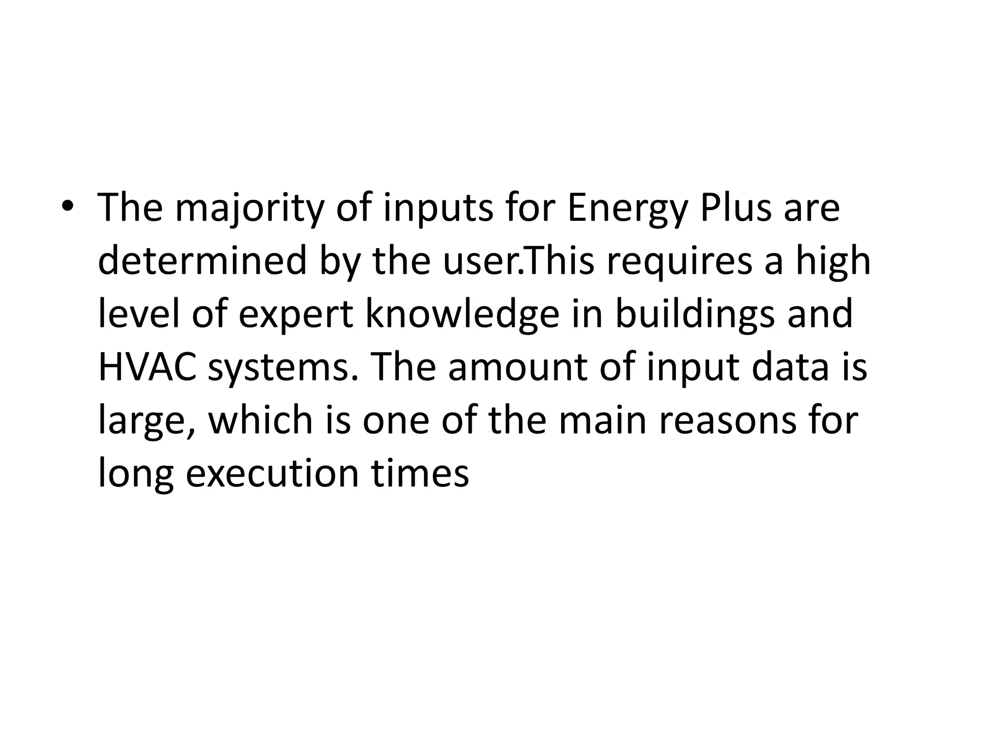
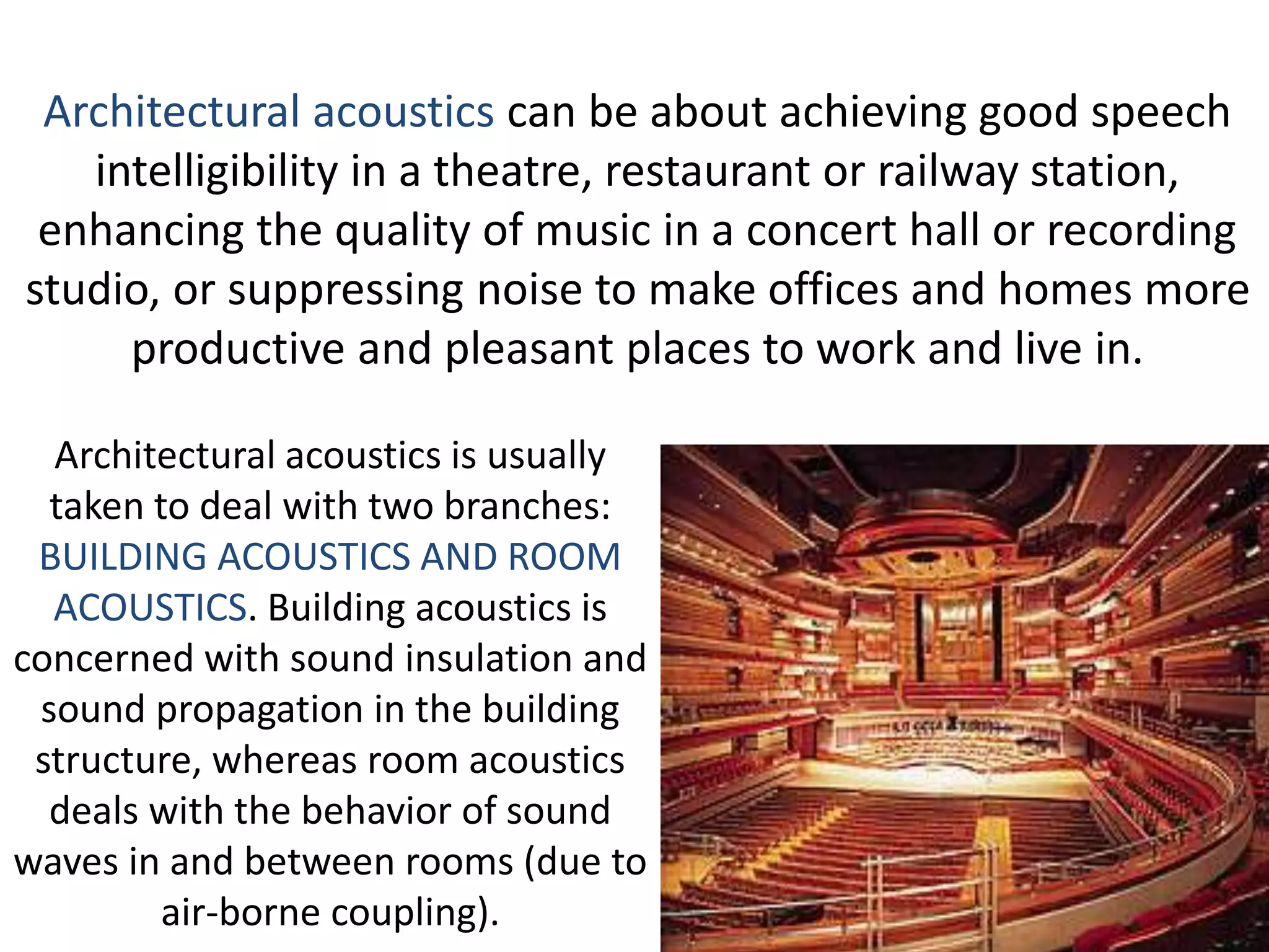
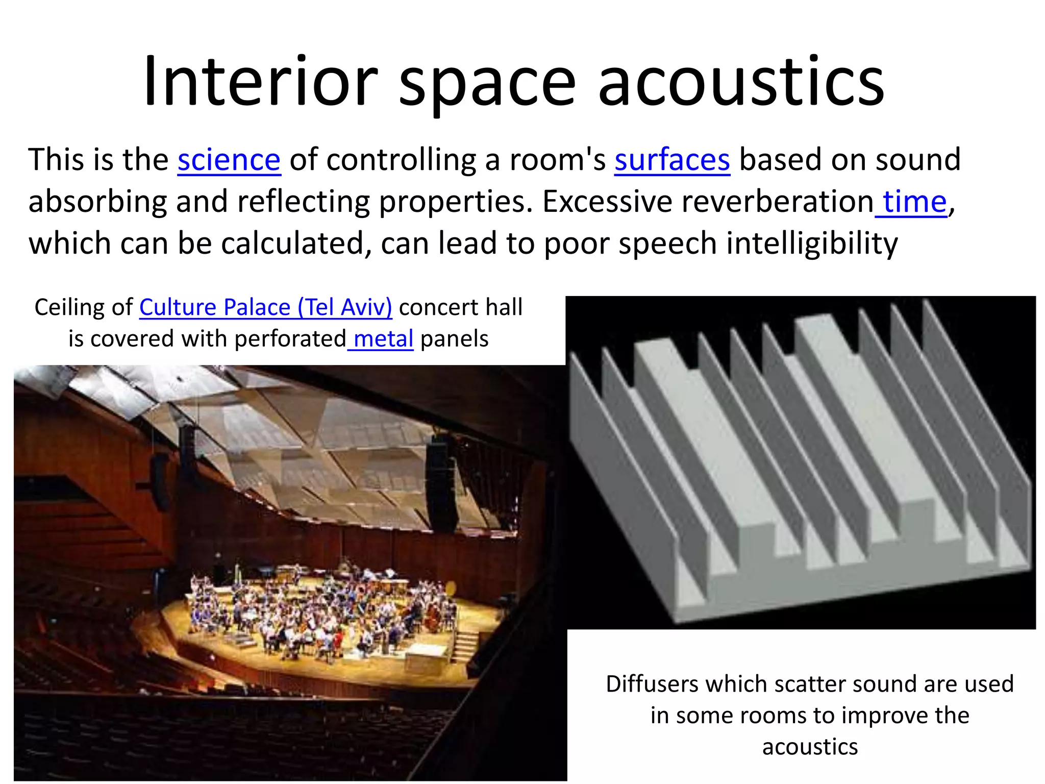
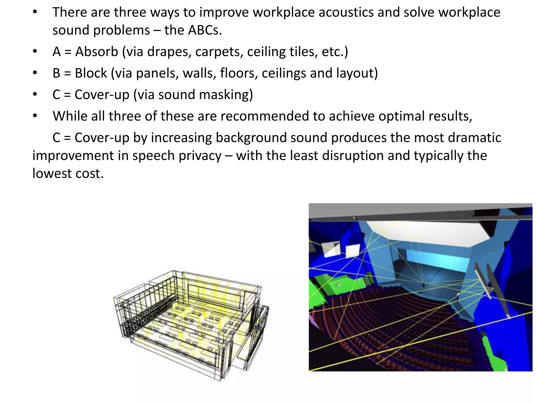
BUILDING SIMULATION, ITS
ROLE, SOFTWARES & THEIR
LIMITATIONS
Efforts by:
PRATIBHA PATIL --------------BA13ARC037
SHREYA SABLE-----------------BA13ARC041
SACHI DONGARWAR---------BA13ARC042
PRASAD THANTHRATEY-----BA13ARC049
The International Building Performance
Simulation Association, is a non-profit
international society of building
performance simulation researchers,
developers and practitioners, dedicated
to improving the built environment.
IBPSA
Building energy simulation is basically the use of software to
predict the energy use of a building.
A typical energy model will have inputs for climate; envelope;
internal gains from lighting, equipment, and occupants;
heating, cooling and ventilation systems; schedules of
occupants, equipment, and lighting.
Energy models will output building energy use predictions in
typical end-use categories: heating, cooling, lighting,
fan, plug, process.
In addition to energy units, most software includes utility
rates input, and can predict energy costs.
Energy-savings measures can be calculated using simple
spreadsheets and a wide variety of bespoke software
applications are available.
Applications
Building design: Many modern commercial or residential
building codes require minimum energy performance.
Energy modelling can be used to demonstrate compliance,
or predict energy consumption of proposed
developments.
Life-cycle cost analysis: Comparing different building
design alternatives to determine which is the least cost,
including capital costs and (at a minimum) energy costs.
Sometimes referred to as Total Cost of
Ownership analysis.
Energy retrofit analysis: In conjunction with an energy
audit, or deep energy retrofit an energy model can be
used to predict savings associated to proposed energy
cost measures (often called ECMs).
โ€ข Autodesk Ecotect Analysis is an environmental analysis tool that allows designers to simulate
building performance from the earliest stages of conceptual design. It
combines analysis functions with an interactive display that presents analytical results directly
within the context of the building model.
โ€ข PROS: The advantage of the admittance method is that it is really fast. Itโ€™s possible to
dynamically interact with your design model and see the effect of material and design
changes, almost in real time. This is a very unique and powerful capability.
Again, this is most useful in early design where relative differences are the important part, not
absolute values.
โ€ข An engagement with simulation and analysis at a time when the design is sufficiently โ€˜plasticโ€™ and
able to respond is critical to achieving the performance demanded of modern buildings
โ€ข CONS: Its thermal analysis results are not accurate enough for rigorous quantitative analysis of a
detailed building. It is NOT useful for detailed hourly analysis or for matching true energy use. It
is best used as an early-stage design tool for comparative analysis. One should only study
relative differences, not absolute values like those needed for regulatory work.
โ€ข Also, because the CIBSE technique is based on a 24 hour cycle, and thermal mass effects can
have a longer time lag, Ecotectโ€™s thermal engine is not suited for precise analysis of thermal
mass.
โ€ข Building thermal simulation tools predict the thermal performance of a
given building and the thermal comfort of its occupants. In general,
they support the understanding of how a given building operates
according to certain criteria and enable comparisons of different
design alternatives.
Building Thermal Simulation
Interoperability of The
Thermal Tools
Summary of data exchange between modelling tools and
thermal simulation tools is shown in the following image.
The linkages include those as interface, add-on or plug-in.
The data exchange is conducted in various formats,
primarily by IFC and gbXML.
โ€ข Interoperability through the BIM platform offers one solution
to the problem of integration. It reduces the time needed to
develop a building and also assures that when the building is
put into operation it will meet the design intent.
โ€ข Interoperability between BIM-based design and energy
simulation tools can improve the workflow between design
deliverables and analysis applications. The challenge that is
facing the BIM is to assure utmost interoperability by
fluidizing model representation, allowing low and high
resolution building models that correspond to all design
phases and allow a design team based model.
โ€ข Although the functionality of the popular building thermal
tools has progressed significantly in the past few years, much
of the potential of their interoperability through BIM remains
largely untapped. Further work is needed to determine if the
appropriate design information for use in thermal analyses
can be captured within a building information model, in
particular their highest priority interoperability
enhancements for the purposes of sustainable building
design.
ADVANTAGES OF BUILDING
SIMULATION
โ€ข There are many advantages of performing a simulation rather than
actually building the design and testing it. The biggest of these
advantages is money. Designing, building, testing, redesigning,
rebuilding, retesting,... for anything can be an expensive project.
Simulations take the building/rebuilding phase out of the loop by
using the model already created in the design phase. Most of the
time the simulation testing is cheaper and faster than performing
the multiple tests of the design each time.
โ€ข The second biggest advantage of a simulation is the level of detail
that you can get from a simulation. A simulation can give you results
that are not experimentally measurable with our current level of
technology.
โ€ข Building Simulation has emerged for use to appraise options for
change in terms of relevant issues โ€“ from human health and comfort
to through energy demand reduction, to sustainable practices.
LIMITATIONS OF BUILDING
SIMULATION
โ€ข Uncertainties are found in any โ€œreal-worldโ€ system, and buildings are no
exception.
โ€ข Uncertainties have been classified in energy building assessment tools in three
different groups:
โ€ข 1. Environmental. Uncertainty in weather prediction under changing climate; and
uncertain weather data information due to the use of synthetic weather data files:
(1) use of synthetic years that do not represent a real year, and
(2) use of a synthetic year that has not been generated from recorded data in the
exact location of the project but in the closest weather station.
โ€ข 2. Workmanship and quality of building elements. Differences between the
design and the real building: Conductivity of thermal bridges, conductivity of
insulation, value of infiltration or U-Values of walls and windows.
โ€ข 3. Behavioural. All other parameters linked to human behaviour i.e. doors and
windows opening use of appliances, occupancy patterns or cooking habits.
โ€ข There are disadvantages to performing a simulation as well. One of
the disadvantages is simulation errors. Any incorrect key stroke has
the potential to alter the results of the simulation and give you the
wrong results.
โ€ข Also usually we are programming using theories of the way things
work not laws. And theories are not often 100% correct. Provided
that you can get your simulation to give you accurate results you
must first run a base line to prove that it works. In order for the
simulation to be accepted in the general community you have to
take experimental results and simulate them. If the two data sets
compare, then any simulation you do of your own design will have
some credibility.
โ€ข The other large disadvantage is the fact that it is a simulation. Many
people do not consider what they do engineering unless they can
see, hear, feel, and taste the project. The virtual world is difficult to
get used to the first time you use it for design.
HVAC
โ€ข The necessity of heating, ventilation, and air-
conditioning (HVAC) control of environmental
conditions within buildings has been well
established over the years as being highly
desirable for various types of occupancy and
comfort conditions as well as for many
industrial manufacturing processes.
โ€ข Some of the more common items that are
generally considered in HVAC are as
follows:
1. Outside design temperatures:
2. Inside design temperatures:
3. Filtration efficiency of supply air
4. Ventilation requirements
5. Exhaust requirements
6. Humidification
7. Dehumidification
8. Air-change rates
Building Energy Modelling Programs (BEMPS)
FOR HVAC:
โ€ข DOE-2
โ€ข ENERGYPLUS} -----US dept. of energy
โ€ข ESP-r ------the University of Strathclyde, U.K.
โ€ข DeST-------Tsinghua University, China.
ROLE OF SOFTWARES:
โ€ข These BEMPs are widely used in the design
stages of new energy efficient buildings, the
planning stages of energy retrofits for existing
buildings, and the development of building
energy codes and standards and energy
labeling programs in the building industry.
DOE-2
METHODOLGY
โ€ข DOE-2 is a program that uses sequential simulation modules.
โ€ข It has one subprogram for the translation of user inputs (the
Building Description Language (BDL)processor), and four simulation
subprograms (LOADS, SYSTEMS, PLANT, and ECON).
โ€ข The SYSTEM and PLANT subprograms constitute the HVAC
subroutines.
โ€ข LOADS, SYSTEMS, and PLANT are executed in sequence.
THE SYSTEM
SUB-PROGRAM
USES OUTPUT INFO FROM LOADS
SUB-PROGRAM
THE PLANT
SUBPROGRAM
USES HOURLY RESULTS FROM THE LOADS AND
SYSTEMS PROGRAMS
Limitations of DOE-2
โ€ข There are several weaknesses in DOE-2.1E software.
โ€ข The main problem is the structure of the software.
โ€ข It has no feedback process, and the one direction
calculation flow contains a lot of simplifications
compared to real HVAC systems.
โ€ข Facing the increasingly complex system schemes and
control methods which are currently emerging, DOE-2
cannot adequately satisfy some user requirements,
particularly those with feedback situations.
DeST
โ€ขDeST separates the heating/cooling station
(central plant)from the supply side, dividing them
into two modules (equivalent user terminal and
heating/cooling station).
โ€ข DeST performs detailed modeling of ducts, chillers, and
pumps in the heating/cooling station side.
โ€ขThe supply air temperature and the supply air volume are
determined in the SCHEME subprogram.
โ€ข The DeST SCHEME module applies an approach to simulating
the hourly zone air temperature under various system
configurations and operations.
โ€ขWith the hourly room air temperatures, supply air temperature,
supply air volume, and other HVAC parameters can be calculated
and HVAC design alternatives can be simulated and evaluated.
ENERGY PLUS
โ€ข EnergyPlus is a powerful simulation program. The
main idea is successive iteration and analogue
simulation. However, Energy Plus allows users to
overwrite internal algorithms or add new calculations
via the Energy Management System feature, which
improves the flexibility of HVAC simulations.
โ€ข To eliminate the necessity of solving the interactions
between pressures and flow rates, EnergyPlus currently
has no duct system model, so the flow rates of
different ducts are determined by a ruled flow resolver.
The flow resolver distributes the flow rate according to
the characteristics of each branch. This assumption is
an effective
โ€ข The majority of inputs for Energy Plus are
determined by the user.This requires a high
level of expert knowledge in buildings and
HVAC systems. The amount of input data is
large, which is one of the main reasons for
long execution times
Architectural acoustics is usually
taken to deal with two branches:
BUILDING ACOUSTICS AND ROOM
ACOUSTICS. Building acoustics is
concerned with sound insulation and
sound propagation in the building
structure, whereas room acoustics
deals with the behavior of sound
waves in and between rooms (due to
air-borne coupling).
Architectural acoustics can be about achieving good speech
intelligibility in a theatre, restaurant or railway station,
enhancing the quality of music in a concert hall or recording
studio, or suppressing noise to make offices and homes more
productive and pleasant places to work and live in.
โ€ข This science analyzes noise transmission from
building exterior envelope to interior and vice
versa. The main noise paths
are roofs, eaves, walls, windows, door and
penetrations. Inter-space noise control.
โ€ข The sound paths are ceilings, room partitions,
acoustic ceiling panels (such as wood dropped
ceiling panels), doors, windows,
flanking, ducting and other penetrations.
Technical solutions depend on the source of the
noise and the path of acoustic transmission, for
example noise by steps or noise by (air, water)
flow vibrations.
Diffusers which scatter sound are used
in some rooms to improve the
acoustics
Interior space acoustics
This is the science of controlling a room's surfaces based on sound
absorbing and reflecting properties. Excessive reverberation time,
which can be calculated, can lead to poor speech intelligibility
Ceiling of Culture Palace (Tel Aviv) concert hall
is covered with perforated metal panels
โ€ข There are three ways to improve workplace acoustics and solve workplace
sound problems โ€“ the ABCs.
โ€ข A = Absorb (via drapes, carpets, ceiling tiles, etc.)
โ€ข B = Block (via panels, walls, floors, ceilings and layout)
โ€ข C = Cover-up (via sound masking)
โ€ข While all three of these are recommended to achieve optimal results,
C = Cover-up by increasing background sound produces the most dramatic
improvement in speech privacy โ€“ with the least disruption and typically the
lowest cost.
โ€ข In the world of acoustic design, it has become essential to use simulation techniques to
predict results before committing to an actual build. In earlier days, designers simply
accepted that they had to build something before they could hear how it sounded.
Even then they brought considerable skill and experience to the task, pursuing a
development cycle that involved the building of numerous prototypes, evaluating what
worked and what didn't, and moving sometimes forward and sometimes backward
until reaching success. But this approach had significant drawbacks: it was very time
consuming, costs were high because many prototypes had to be built, and many of the
designs were of no value and had to be discarded.
โ€ข Acoustic simulation was developed as a way to resolve these difficulties. Simulation
makes it possible to identify properties and conditions that will adversely affect
acoustics while still working at the design stage, so that these can be eliminated before
building a prototype. With the advent of simulation, design quality went up, and the
time and costs of product development fell rapidly.
Simulation technology uses computers to visually and objectively display and
analyze the acoustic and other physical phenomena that will occur under given
sets of conditions. In particular, the technology can:
โ€ขAssess the reality: Analyze what happens under these conditions.
โ€ขAnalyze the causes: Analyze why these things are happening.
โ€ขPredict: Predict what is likely to occur.
It is an easy matter to conduct many simulations under different conditional
settingsโ€”from ideal conditions to extremeโ€”making it possible to quickly test
a wide variety of conditions that could not be tested before
Sound Rendering: An Overview
ยฉ Copyright 2009 Anish Chandak
Modeling
Acoustic Geometry
-- surface simplification
Source Modeling
-- area source
-- emitting characteristics
-- sound signal
Acoustic Material
-- absorption coefficient
-- scattering coefficient
Rendering
Personalized HRTFs
for 3D sound
Late Reverberation
Digital Signal Processing
Interpolation for
Dynamic Scenes
Scientific Visualization
Propagation
Diffraction
Refraction
Doppler Effect
Attenuation
Specular Reflection
Scattering
โ€ข There are two main approaches in room acoustic modeling.
โ€ข The more accurate one is based on solving the actual wave
equation numerically. Techniques using this approach are
called wave-based. The wave-based methods are most suitable
for low frequencies.
โ€ข The other approach is based on geometrical acoustics in which
sound is supposed to act as rays and the wavelength of sound
is neglected. These methods are called ray-based since they
often use some kind of rays or particles that are reflected at
the surfaces of the room.
โ€ข Acoustic radiance transfer method is one of the newest
techniques based on geometrical acoustics . It is kind of a
hybrid of both approaches
โ€ข Important aspects in acoustics simulation are:
1. Time
2. Direction
3. Frequency
The instruments used in this
process are
โ€ข Electroacoustic
equipment
โ€ข Microphones and input
equipment
โ€ข Loudspeakers
Odeon:ODEON software is developed for simulating and measuring the
interior acoustics of buildings. With the appropriate treatment
outdoor situations can be studied as well. Given the geometry and
surface-properties, the acoustics can be predicted, illustrated and
listened to. Sound reinforcement is easily integrated in the acoustic
predictions.
ODEON uses the image-source method
combined with ray tracing.
Applications include:
1.Concert and opera halls, theatres, churches and
mosques
2.Open plan offices, foyers, restaurants, music studios
3.Underground and railway stations, airport terminals
4.Industrial Environments, Outdoor areas with
complicated geometry
ODEON is available in four editions:
โ€ข The Basics edition that gives a collection of the ODEON powerful tools
in affordable cost. ODEON basics comes with a measuring system and
basic simulation tools. The computation engine and accuracy is exactly
the same as for the rest versions.
โ€ข The Industrial edition for environmental acoustics where SPL, SPL(A),
T30 and STI are the important results. It allows modeling of point, line
and surface sources, with possibility to model large and complex sound
sources.
โ€ข The Auditorium edition for a large set of room acoustical parameters
based on the reverberation curve. It has a variety of graphical and
auralisation tools.
โ€ข The Combined edition includes all the features found in the Basics,
Industrial and Auditorium editions.
OTHER SOFTWARES for acoustics
simulation in architecture.
โ€ข JOCAVI
โ€ข CARA-Computer Aided Room Acoustics
โ€ข EASE-Enhanced Acoustic Simulator for
Engineers
โ€ข COMSOL
โ€ข RAMSETE
BUILDING SIMULATION FOR
LIGHTING ANALYSIS
Lighting analysis software and rendering tools can help you simulate lighting and
daylighting in your building. Both quantitative and qualitative analysis are important.
โ— DAYLIGHT INTEGRATION
โ— ILLUMINATION DESIGN
SCOPE
โ— Urban planning
Applications include indicating height variety in high-rise complexes, which ensures daylight
access for lower floors. Urban profiles for high density but with solar access are recommended by
the tool proposed. Proportions of urban squares and urban planting positions can be studied
employing the program developed . Such simulation models can additionally be used to verify
construction code compliance .
โ— Early design stages
Few provide analysis or suggested solutions. During early design phases, architects should
compare interactively the outcome of their intentions. Some tools have been proposed for use
during these stages, such as Lightsolve and virtual heliodons.
โ— Design
Current lighting simulation models can be used after deciding on fundamental issues such as
massing, building position, window size and orientation. Examination of artificial lighting layouts is
facilitated by tools dedicated to that purpose. Experts are needed to determine maximum
performance of specific building components such as glazing and redirecting systems, shades and
blinds, and control modes for automated shading and lighting.
REQUIREMENTS OF A GOOD SIMULATION ENGINE
โ— Simulation based design aid tools that address lighting issues require a lighting
analysis engine capable of determining interior lighting levels and some
measure of lighting comfort.
โ— These building performance characteristics must be calculated, using actual
weather data as input, so that both spatial distribution within a building interior
and temporal variations during an individual day and throughout an entire year,
can be assessed.
โ— The engine must be fast enough to allow rapid experimentation with various
lighting design parameters.
โ— The engine must also be robust enough to accurately account for variations in
design parameters such as room and building site configuration, interior and
exterior surface reflectance, complex fenestration system types, and commercial
electric lighting system types.
โ— The engine itself, or its simulation results, must be easily integrated with whole
building analysis to account for design interdependencies between daylighting,
electric lighting and thermal performance.
BASIS
โ— VISIBILITY
โ— TASK PERFORMANCE
โ— MOOD AND ATMOSPHERE
โ— VISUAL COMFORT
โ— SAFETY
โ— SOLVING LIGHTING PROBLEMS
- OVERHEAD GLARE
- VEILING GLARE
- SHADOWING
- GLOOM
- STROBOSCOPIC EFFECT
Daylight Analysis in BIM
We can understand and quantify the amount of the sunโ€™s light in your project with
daylighting analysis. This can help you create comfortable and beautiful spaces, reduce
lighting loads, and reduce cooling loads. There are many ways to measure and visualize
light, and you may use different tools depending on which question youโ€™re trying to
answer.
โ— Radiance: Accurate Daylighting
โ— Daysim: Daylighting w. Controls
โ— 3ds Max: Daylighting Visualization
โ— Ecotect: Early Daylighting Studies
Artificial Lighting
โ— 3dsMax
โ— Photorealistic Rendering
โ— Revit: Illuminance Simulations
Simulation software must answer...
โ— Can you improve the form of the building/room to get more natural
light?
โ— Can you get enough light for specific tasks?
โ— How much can you offset artificial lights with daylight?
โ— Is light well distributed and not causing glare?
ECOTECT
Ecotect is a useful tool for early design studies that quantify daylight factor and
visualize light rays. The software is designed to aid in the simulation, analysis
and optimization of high performance buildings and systems Its native
daylighting engine is not accurate enough to be used beyond early conceptual
design.
It has built-in connections with more sophisticated tools like RADIANCE and
DAYSIM, and can help visualize results from those programs.
โ— Qualitative Analysis: Visualizing Light Rays in Ecotect
โ— Quantitative Analysis: Calculating Daylight Factors in Ecotect
โ— Shading Design Wizard
โ— The strength of the software is the way it helps
users visualize very complex simulation data.
strength of the software is the way it helps
users visualize very complex simulation data.
โ— The design and performance analysis tools also
take advantage of cutting edge 3D spatial
models to help users visualize simulation
output, smoothing the translation of simulation
results into the project design.
โ— Using simulation software, design professionals
are able to continuously study and predict how
decisions will impact the performance of the
building from the early phases of design
through occupancy without significant
investment in mockups or manual calculations.
โ— ECOTECT and other similar software have the
potential to revolutionize the building industry
by giving architects and engineers the power to
use performance based criteria in the design of
projects.
RADIANCE
It is a physically accurate and comprehensive lighting analysis tool that can be
accessed via Ecotect 2011. It can help accurately calculate
โ— daylight factor-A daylight factor is the ratio of internal light level to external light level and is defined
as follows: DF = (Ei / Eo) x 100% where, Ei = illuminance due to daylight at a point on the indoors working
plane, Eo = simultaneous outdoor illuminance on a horizontal plane from an unobstructed hemisphere of
overcast sky.
โ— illuminance-It is a measure of how much light falls on a surface. It is useful for determining
whether or not there is enough light to perform different activities (like reading, office work, or
drafting). Illuminance is measured in lux or footcandles (1 footcandle = 10.7 lux).
An illuminance rendering shows you whether your lighting design meets the requirements of the
space, and it also helps you understand how much of this light youโ€™ll be able to get from daylighting.
โ— luminance- reflected light
โ— daylight autonomy
โ— Skylight factor
โ— Glare and indoor comfort
โ— time of the year and geographical location
Daylight Optimization and the Design Process
โ— Itโ€™s important to remember that computer simulations take time. The first step is to have a clear vision of
how the results will help you improve your design. You may be able to use hand calculations and rules of
thumb to get started.
โ— Early-on in the design process, daylight feasibility analysis in BIM should be done in conjunction with solar
loads analysis and sun and shadow studies.
โ— To avoid glare, youโ€™ll want to avoid the penetration of direct sun. And, since daylight is a form of radiation
(short wave, within the visible spectrum), studying solar radiation can give you a sense for how much light
you may be able to pull in from different sides of the building.
โ— Often designers use previous experience and rules of thumb during these early phases. But when using BIM,
you typically want to study conceptual rooms for their overall shape, aperture layout and size, and general
shading strategies. Metrics to consider are the average daylight factor for the space.
โ— Later in the design process, you can really hone-in on the daylight to test for interior visual comfort. This is
where computer simulations and lighting consultants typically come in. Often this work involves quickly
testing different design parameters like shading features, glazing properties, and window placement.
Simulation results are usually calculated on a workplane and from specific vantage points (head height of a
worker).

Building Simulation, Its Role, Softwares & Their Limitations

  • 1.
    BUILDING SIMULATION, ITS ROLE,SOFTWARES & THEIR LIMITATIONS Efforts by: PRATIBHA PATIL --------------BA13ARC037 SHREYA SABLE-----------------BA13ARC041 SACHI DONGARWAR---------BA13ARC042 PRASAD THANTHRATEY-----BA13ARC049
  • 2.
    The International BuildingPerformance Simulation Association, is a non-profit international society of building performance simulation researchers, developers and practitioners, dedicated to improving the built environment. IBPSA
  • 3.
    Building energy simulationis basically the use of software to predict the energy use of a building. A typical energy model will have inputs for climate; envelope; internal gains from lighting, equipment, and occupants; heating, cooling and ventilation systems; schedules of occupants, equipment, and lighting. Energy models will output building energy use predictions in typical end-use categories: heating, cooling, lighting, fan, plug, process. In addition to energy units, most software includes utility rates input, and can predict energy costs. Energy-savings measures can be calculated using simple spreadsheets and a wide variety of bespoke software applications are available.
  • 4.
    Applications Building design: Manymodern commercial or residential building codes require minimum energy performance. Energy modelling can be used to demonstrate compliance, or predict energy consumption of proposed developments. Life-cycle cost analysis: Comparing different building design alternatives to determine which is the least cost, including capital costs and (at a minimum) energy costs. Sometimes referred to as Total Cost of Ownership analysis. Energy retrofit analysis: In conjunction with an energy audit, or deep energy retrofit an energy model can be used to predict savings associated to proposed energy cost measures (often called ECMs).
  • 5.
    โ€ข Autodesk EcotectAnalysis is an environmental analysis tool that allows designers to simulate building performance from the earliest stages of conceptual design. It combines analysis functions with an interactive display that presents analytical results directly within the context of the building model. โ€ข PROS: The advantage of the admittance method is that it is really fast. Itโ€™s possible to dynamically interact with your design model and see the effect of material and design changes, almost in real time. This is a very unique and powerful capability. Again, this is most useful in early design where relative differences are the important part, not absolute values. โ€ข An engagement with simulation and analysis at a time when the design is sufficiently โ€˜plasticโ€™ and able to respond is critical to achieving the performance demanded of modern buildings โ€ข CONS: Its thermal analysis results are not accurate enough for rigorous quantitative analysis of a detailed building. It is NOT useful for detailed hourly analysis or for matching true energy use. It is best used as an early-stage design tool for comparative analysis. One should only study relative differences, not absolute values like those needed for regulatory work. โ€ข Also, because the CIBSE technique is based on a 24 hour cycle, and thermal mass effects can have a longer time lag, Ecotectโ€™s thermal engine is not suited for precise analysis of thermal mass.
  • 6.
    โ€ข Building thermalsimulation tools predict the thermal performance of a given building and the thermal comfort of its occupants. In general, they support the understanding of how a given building operates according to certain criteria and enable comparisons of different design alternatives. Building Thermal Simulation
  • 7.
  • 10.
    Summary of dataexchange between modelling tools and thermal simulation tools is shown in the following image. The linkages include those as interface, add-on or plug-in. The data exchange is conducted in various formats, primarily by IFC and gbXML.
  • 12.
    โ€ข Interoperability throughthe BIM platform offers one solution to the problem of integration. It reduces the time needed to develop a building and also assures that when the building is put into operation it will meet the design intent. โ€ข Interoperability between BIM-based design and energy simulation tools can improve the workflow between design deliverables and analysis applications. The challenge that is facing the BIM is to assure utmost interoperability by fluidizing model representation, allowing low and high resolution building models that correspond to all design phases and allow a design team based model. โ€ข Although the functionality of the popular building thermal tools has progressed significantly in the past few years, much of the potential of their interoperability through BIM remains largely untapped. Further work is needed to determine if the appropriate design information for use in thermal analyses can be captured within a building information model, in particular their highest priority interoperability enhancements for the purposes of sustainable building design.
  • 13.
    ADVANTAGES OF BUILDING SIMULATION โ€ขThere are many advantages of performing a simulation rather than actually building the design and testing it. The biggest of these advantages is money. Designing, building, testing, redesigning, rebuilding, retesting,... for anything can be an expensive project. Simulations take the building/rebuilding phase out of the loop by using the model already created in the design phase. Most of the time the simulation testing is cheaper and faster than performing the multiple tests of the design each time. โ€ข The second biggest advantage of a simulation is the level of detail that you can get from a simulation. A simulation can give you results that are not experimentally measurable with our current level of technology. โ€ข Building Simulation has emerged for use to appraise options for change in terms of relevant issues โ€“ from human health and comfort to through energy demand reduction, to sustainable practices.
  • 14.
    LIMITATIONS OF BUILDING SIMULATION โ€ขUncertainties are found in any โ€œreal-worldโ€ system, and buildings are no exception. โ€ข Uncertainties have been classified in energy building assessment tools in three different groups: โ€ข 1. Environmental. Uncertainty in weather prediction under changing climate; and uncertain weather data information due to the use of synthetic weather data files: (1) use of synthetic years that do not represent a real year, and (2) use of a synthetic year that has not been generated from recorded data in the exact location of the project but in the closest weather station. โ€ข 2. Workmanship and quality of building elements. Differences between the design and the real building: Conductivity of thermal bridges, conductivity of insulation, value of infiltration or U-Values of walls and windows. โ€ข 3. Behavioural. All other parameters linked to human behaviour i.e. doors and windows opening use of appliances, occupancy patterns or cooking habits.
  • 15.
    โ€ข There aredisadvantages to performing a simulation as well. One of the disadvantages is simulation errors. Any incorrect key stroke has the potential to alter the results of the simulation and give you the wrong results. โ€ข Also usually we are programming using theories of the way things work not laws. And theories are not often 100% correct. Provided that you can get your simulation to give you accurate results you must first run a base line to prove that it works. In order for the simulation to be accepted in the general community you have to take experimental results and simulate them. If the two data sets compare, then any simulation you do of your own design will have some credibility. โ€ข The other large disadvantage is the fact that it is a simulation. Many people do not consider what they do engineering unless they can see, hear, feel, and taste the project. The virtual world is difficult to get used to the first time you use it for design.
  • 16.
    HVAC โ€ข The necessityof heating, ventilation, and air- conditioning (HVAC) control of environmental conditions within buildings has been well established over the years as being highly desirable for various types of occupancy and comfort conditions as well as for many industrial manufacturing processes.
  • 17.
    โ€ข Some ofthe more common items that are generally considered in HVAC are as follows: 1. Outside design temperatures: 2. Inside design temperatures: 3. Filtration efficiency of supply air 4. Ventilation requirements 5. Exhaust requirements 6. Humidification 7. Dehumidification 8. Air-change rates
  • 18.
    Building Energy ModellingPrograms (BEMPS) FOR HVAC: โ€ข DOE-2 โ€ข ENERGYPLUS} -----US dept. of energy โ€ข ESP-r ------the University of Strathclyde, U.K. โ€ข DeST-------Tsinghua University, China.
  • 19.
    ROLE OF SOFTWARES: โ€ขThese BEMPs are widely used in the design stages of new energy efficient buildings, the planning stages of energy retrofits for existing buildings, and the development of building energy codes and standards and energy labeling programs in the building industry.
  • 21.
  • 22.
    METHODOLGY โ€ข DOE-2 isa program that uses sequential simulation modules. โ€ข It has one subprogram for the translation of user inputs (the Building Description Language (BDL)processor), and four simulation subprograms (LOADS, SYSTEMS, PLANT, and ECON). โ€ข The SYSTEM and PLANT subprograms constitute the HVAC subroutines. โ€ข LOADS, SYSTEMS, and PLANT are executed in sequence. THE SYSTEM SUB-PROGRAM USES OUTPUT INFO FROM LOADS SUB-PROGRAM THE PLANT SUBPROGRAM USES HOURLY RESULTS FROM THE LOADS AND SYSTEMS PROGRAMS
  • 23.
    Limitations of DOE-2 โ€ขThere are several weaknesses in DOE-2.1E software. โ€ข The main problem is the structure of the software. โ€ข It has no feedback process, and the one direction calculation flow contains a lot of simplifications compared to real HVAC systems. โ€ข Facing the increasingly complex system schemes and control methods which are currently emerging, DOE-2 cannot adequately satisfy some user requirements, particularly those with feedback situations.
  • 24.
    DeST โ€ขDeST separates theheating/cooling station (central plant)from the supply side, dividing them into two modules (equivalent user terminal and heating/cooling station). โ€ข DeST performs detailed modeling of ducts, chillers, and pumps in the heating/cooling station side. โ€ขThe supply air temperature and the supply air volume are determined in the SCHEME subprogram. โ€ข The DeST SCHEME module applies an approach to simulating the hourly zone air temperature under various system configurations and operations. โ€ขWith the hourly room air temperatures, supply air temperature, supply air volume, and other HVAC parameters can be calculated and HVAC design alternatives can be simulated and evaluated.
  • 25.
    ENERGY PLUS โ€ข EnergyPlusis a powerful simulation program. The main idea is successive iteration and analogue simulation. However, Energy Plus allows users to overwrite internal algorithms or add new calculations via the Energy Management System feature, which improves the flexibility of HVAC simulations. โ€ข To eliminate the necessity of solving the interactions between pressures and flow rates, EnergyPlus currently has no duct system model, so the flow rates of different ducts are determined by a ruled flow resolver. The flow resolver distributes the flow rate according to the characteristics of each branch. This assumption is an effective
  • 26.
    โ€ข The majorityof inputs for Energy Plus are determined by the user.This requires a high level of expert knowledge in buildings and HVAC systems. The amount of input data is large, which is one of the main reasons for long execution times
  • 30.
    Architectural acoustics isusually taken to deal with two branches: BUILDING ACOUSTICS AND ROOM ACOUSTICS. Building acoustics is concerned with sound insulation and sound propagation in the building structure, whereas room acoustics deals with the behavior of sound waves in and between rooms (due to air-borne coupling). Architectural acoustics can be about achieving good speech intelligibility in a theatre, restaurant or railway station, enhancing the quality of music in a concert hall or recording studio, or suppressing noise to make offices and homes more productive and pleasant places to work and live in.
  • 31.
    โ€ข This scienceanalyzes noise transmission from building exterior envelope to interior and vice versa. The main noise paths are roofs, eaves, walls, windows, door and penetrations. Inter-space noise control. โ€ข The sound paths are ceilings, room partitions, acoustic ceiling panels (such as wood dropped ceiling panels), doors, windows, flanking, ducting and other penetrations. Technical solutions depend on the source of the noise and the path of acoustic transmission, for example noise by steps or noise by (air, water) flow vibrations.
  • 32.
    Diffusers which scattersound are used in some rooms to improve the acoustics Interior space acoustics This is the science of controlling a room's surfaces based on sound absorbing and reflecting properties. Excessive reverberation time, which can be calculated, can lead to poor speech intelligibility Ceiling of Culture Palace (Tel Aviv) concert hall is covered with perforated metal panels
  • 33.
    โ€ข There arethree ways to improve workplace acoustics and solve workplace sound problems โ€“ the ABCs. โ€ข A = Absorb (via drapes, carpets, ceiling tiles, etc.) โ€ข B = Block (via panels, walls, floors, ceilings and layout) โ€ข C = Cover-up (via sound masking) โ€ข While all three of these are recommended to achieve optimal results, C = Cover-up by increasing background sound produces the most dramatic improvement in speech privacy โ€“ with the least disruption and typically the lowest cost.
  • 34.
    โ€ข In theworld of acoustic design, it has become essential to use simulation techniques to predict results before committing to an actual build. In earlier days, designers simply accepted that they had to build something before they could hear how it sounded. Even then they brought considerable skill and experience to the task, pursuing a development cycle that involved the building of numerous prototypes, evaluating what worked and what didn't, and moving sometimes forward and sometimes backward until reaching success. But this approach had significant drawbacks: it was very time consuming, costs were high because many prototypes had to be built, and many of the designs were of no value and had to be discarded. โ€ข Acoustic simulation was developed as a way to resolve these difficulties. Simulation makes it possible to identify properties and conditions that will adversely affect acoustics while still working at the design stage, so that these can be eliminated before building a prototype. With the advent of simulation, design quality went up, and the time and costs of product development fell rapidly.
  • 35.
    Simulation technology usescomputers to visually and objectively display and analyze the acoustic and other physical phenomena that will occur under given sets of conditions. In particular, the technology can: โ€ขAssess the reality: Analyze what happens under these conditions. โ€ขAnalyze the causes: Analyze why these things are happening. โ€ขPredict: Predict what is likely to occur. It is an easy matter to conduct many simulations under different conditional settingsโ€”from ideal conditions to extremeโ€”making it possible to quickly test a wide variety of conditions that could not be tested before
  • 36.
    Sound Rendering: AnOverview ยฉ Copyright 2009 Anish Chandak Modeling Acoustic Geometry -- surface simplification Source Modeling -- area source -- emitting characteristics -- sound signal Acoustic Material -- absorption coefficient -- scattering coefficient Rendering Personalized HRTFs for 3D sound Late Reverberation Digital Signal Processing Interpolation for Dynamic Scenes Scientific Visualization Propagation Diffraction Refraction Doppler Effect Attenuation Specular Reflection Scattering
  • 37.
    Sound Rendering: AnOverview ยฉ Copyright 2009 Anish Chandak Modeling Acoustic Geometry -- surface simplification Source Modeling -- area source -- emitting characteristics -- sound signal Acoustic Material -- absorption coefficient -- scattering coefficient Rendering Personalized HRTFs for 3D sound Late Reverberation Digital Signal Processing Interpolation for Dynamic Scenes Scientific Visualization Propagation Diffraction Refraction Doppler Effect Attenuation Specular Reflection Scattering
  • 38.
    โ€ข There aretwo main approaches in room acoustic modeling. โ€ข The more accurate one is based on solving the actual wave equation numerically. Techniques using this approach are called wave-based. The wave-based methods are most suitable for low frequencies. โ€ข The other approach is based on geometrical acoustics in which sound is supposed to act as rays and the wavelength of sound is neglected. These methods are called ray-based since they often use some kind of rays or particles that are reflected at the surfaces of the room. โ€ข Acoustic radiance transfer method is one of the newest techniques based on geometrical acoustics . It is kind of a hybrid of both approaches
  • 39.
    โ€ข Important aspectsin acoustics simulation are: 1. Time 2. Direction 3. Frequency The instruments used in this process are โ€ข Electroacoustic equipment โ€ข Microphones and input equipment โ€ข Loudspeakers
  • 40.
    Odeon:ODEON software isdeveloped for simulating and measuring the interior acoustics of buildings. With the appropriate treatment outdoor situations can be studied as well. Given the geometry and surface-properties, the acoustics can be predicted, illustrated and listened to. Sound reinforcement is easily integrated in the acoustic predictions. ODEON uses the image-source method combined with ray tracing.
  • 41.
    Applications include: 1.Concert andopera halls, theatres, churches and mosques 2.Open plan offices, foyers, restaurants, music studios 3.Underground and railway stations, airport terminals 4.Industrial Environments, Outdoor areas with complicated geometry
  • 42.
    ODEON is availablein four editions: โ€ข The Basics edition that gives a collection of the ODEON powerful tools in affordable cost. ODEON basics comes with a measuring system and basic simulation tools. The computation engine and accuracy is exactly the same as for the rest versions. โ€ข The Industrial edition for environmental acoustics where SPL, SPL(A), T30 and STI are the important results. It allows modeling of point, line and surface sources, with possibility to model large and complex sound sources. โ€ข The Auditorium edition for a large set of room acoustical parameters based on the reverberation curve. It has a variety of graphical and auralisation tools. โ€ข The Combined edition includes all the features found in the Basics, Industrial and Auditorium editions.
  • 43.
    OTHER SOFTWARES foracoustics simulation in architecture. โ€ข JOCAVI โ€ข CARA-Computer Aided Room Acoustics โ€ข EASE-Enhanced Acoustic Simulator for Engineers โ€ข COMSOL โ€ข RAMSETE
  • 44.
    BUILDING SIMULATION FOR LIGHTINGANALYSIS Lighting analysis software and rendering tools can help you simulate lighting and daylighting in your building. Both quantitative and qualitative analysis are important. โ— DAYLIGHT INTEGRATION โ— ILLUMINATION DESIGN
  • 45.
    SCOPE โ— Urban planning Applicationsinclude indicating height variety in high-rise complexes, which ensures daylight access for lower floors. Urban profiles for high density but with solar access are recommended by the tool proposed. Proportions of urban squares and urban planting positions can be studied employing the program developed . Such simulation models can additionally be used to verify construction code compliance . โ— Early design stages Few provide analysis or suggested solutions. During early design phases, architects should compare interactively the outcome of their intentions. Some tools have been proposed for use during these stages, such as Lightsolve and virtual heliodons. โ— Design Current lighting simulation models can be used after deciding on fundamental issues such as massing, building position, window size and orientation. Examination of artificial lighting layouts is facilitated by tools dedicated to that purpose. Experts are needed to determine maximum performance of specific building components such as glazing and redirecting systems, shades and blinds, and control modes for automated shading and lighting.
  • 47.
    REQUIREMENTS OF AGOOD SIMULATION ENGINE โ— Simulation based design aid tools that address lighting issues require a lighting analysis engine capable of determining interior lighting levels and some measure of lighting comfort. โ— These building performance characteristics must be calculated, using actual weather data as input, so that both spatial distribution within a building interior and temporal variations during an individual day and throughout an entire year, can be assessed. โ— The engine must be fast enough to allow rapid experimentation with various lighting design parameters. โ— The engine must also be robust enough to accurately account for variations in design parameters such as room and building site configuration, interior and exterior surface reflectance, complex fenestration system types, and commercial electric lighting system types. โ— The engine itself, or its simulation results, must be easily integrated with whole building analysis to account for design interdependencies between daylighting, electric lighting and thermal performance.
  • 48.
    BASIS โ— VISIBILITY โ— TASKPERFORMANCE โ— MOOD AND ATMOSPHERE โ— VISUAL COMFORT โ— SAFETY โ— SOLVING LIGHTING PROBLEMS - OVERHEAD GLARE - VEILING GLARE - SHADOWING - GLOOM - STROBOSCOPIC EFFECT
  • 49.
    Daylight Analysis inBIM We can understand and quantify the amount of the sunโ€™s light in your project with daylighting analysis. This can help you create comfortable and beautiful spaces, reduce lighting loads, and reduce cooling loads. There are many ways to measure and visualize light, and you may use different tools depending on which question youโ€™re trying to answer. โ— Radiance: Accurate Daylighting โ— Daysim: Daylighting w. Controls โ— 3ds Max: Daylighting Visualization โ— Ecotect: Early Daylighting Studies Artificial Lighting โ— 3dsMax โ— Photorealistic Rendering โ— Revit: Illuminance Simulations
  • 50.
    Simulation software mustanswer... โ— Can you improve the form of the building/room to get more natural light? โ— Can you get enough light for specific tasks? โ— How much can you offset artificial lights with daylight? โ— Is light well distributed and not causing glare?
  • 52.
    ECOTECT Ecotect is auseful tool for early design studies that quantify daylight factor and visualize light rays. The software is designed to aid in the simulation, analysis and optimization of high performance buildings and systems Its native daylighting engine is not accurate enough to be used beyond early conceptual design. It has built-in connections with more sophisticated tools like RADIANCE and DAYSIM, and can help visualize results from those programs. โ— Qualitative Analysis: Visualizing Light Rays in Ecotect โ— Quantitative Analysis: Calculating Daylight Factors in Ecotect โ— Shading Design Wizard
  • 53.
    โ— The strengthof the software is the way it helps users visualize very complex simulation data. strength of the software is the way it helps users visualize very complex simulation data. โ— The design and performance analysis tools also take advantage of cutting edge 3D spatial models to help users visualize simulation output, smoothing the translation of simulation results into the project design. โ— Using simulation software, design professionals are able to continuously study and predict how decisions will impact the performance of the building from the early phases of design through occupancy without significant investment in mockups or manual calculations. โ— ECOTECT and other similar software have the potential to revolutionize the building industry by giving architects and engineers the power to use performance based criteria in the design of projects.
  • 55.
    RADIANCE It is aphysically accurate and comprehensive lighting analysis tool that can be accessed via Ecotect 2011. It can help accurately calculate โ— daylight factor-A daylight factor is the ratio of internal light level to external light level and is defined as follows: DF = (Ei / Eo) x 100% where, Ei = illuminance due to daylight at a point on the indoors working plane, Eo = simultaneous outdoor illuminance on a horizontal plane from an unobstructed hemisphere of overcast sky. โ— illuminance-It is a measure of how much light falls on a surface. It is useful for determining whether or not there is enough light to perform different activities (like reading, office work, or drafting). Illuminance is measured in lux or footcandles (1 footcandle = 10.7 lux). An illuminance rendering shows you whether your lighting design meets the requirements of the space, and it also helps you understand how much of this light youโ€™ll be able to get from daylighting. โ— luminance- reflected light โ— daylight autonomy โ— Skylight factor โ— Glare and indoor comfort โ— time of the year and geographical location
  • 57.
    Daylight Optimization andthe Design Process โ— Itโ€™s important to remember that computer simulations take time. The first step is to have a clear vision of how the results will help you improve your design. You may be able to use hand calculations and rules of thumb to get started. โ— Early-on in the design process, daylight feasibility analysis in BIM should be done in conjunction with solar loads analysis and sun and shadow studies. โ— To avoid glare, youโ€™ll want to avoid the penetration of direct sun. And, since daylight is a form of radiation (short wave, within the visible spectrum), studying solar radiation can give you a sense for how much light you may be able to pull in from different sides of the building. โ— Often designers use previous experience and rules of thumb during these early phases. But when using BIM, you typically want to study conceptual rooms for their overall shape, aperture layout and size, and general shading strategies. Metrics to consider are the average daylight factor for the space. โ— Later in the design process, you can really hone-in on the daylight to test for interior visual comfort. This is where computer simulations and lighting consultants typically come in. Often this work involves quickly testing different design parameters like shading features, glazing properties, and window placement. Simulation results are usually calculated on a workplane and from specific vantage points (head height of a worker).

Editor's Notes

  • #37ย 1) The goal of Graphics is simulating visual reality in virtual world. The goal of sound rendering is simulating acoustic reality in a virtual world. TALK MORE. What is acoustic reality. 2) 3 big components of sound rendering. 3) So you can see that there are lot of things that need to be covered and I got only one lecture so you are not going to learn everything.
  • #38ย 1) But what you will learn is how to model geometry for acoustic simulations. 2) How to handle specular reflections and diffuse reflections. Here a lot of your graphics knowledge will come handy. Which I am sure you are experts of by now. 3) And one very important thing is how to be able to simulate 3D audio (direction where sound is coming from). 4) IMPORTANT. I will talk about propagation first. And a big chunk of the lecture will be devoted to it. And we will talk a little bit about Acoustic Geometry and 3D Audio at the very end.