Downloaded 2,782 times
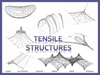
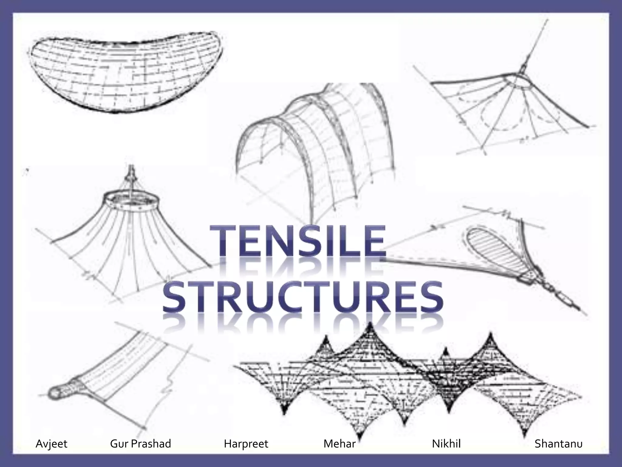
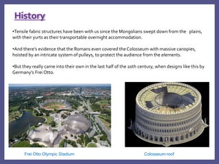
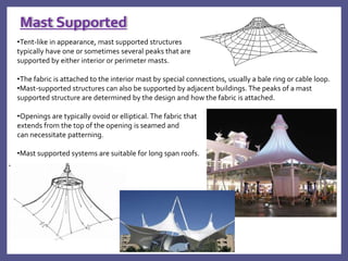
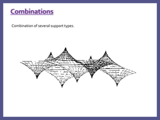
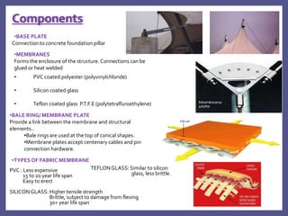
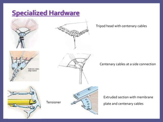
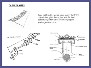
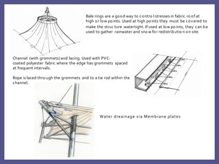
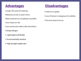

The document discusses tensile structures, which are buildings that rely on tension in components like cables and fabrics to bear loads. Tensile structures include boundary tensioned membranes, pneumatic structures, and pre-stressed cable nets. They have been used historically in structures like yurts and the Colosseum roof. Tensile structures take saddle, mast-supported, arch-supported, and combination forms. Key components are membranes, bale rings, plates, and specialized hardware. Advantages include long lifecycles, reusability, recyclability, and unique designs, while disadvantages include lack of rigidity and danger if tension is lost.


